Báo cáo hóa học: " A Visual Environment for Real-Time Image Processing in Hardware (VERTIPH)" pdf
Bạn đang xem bản rút gọn của tài liệu. Xem và tải ngay bản đầy đủ của tài liệu tại đây (972.23 KB, 8 trang )
Hindawi Publishing Corporation
EURASIP Journal on Embedded Systems
Volume 2006, Article ID 72962, Pages 1–8
DOI 10.1155/ES/2006/72962
A Visual Environment for Real-Time Image Processing
in Hardware (VERTIPH)
C. T. Johnston, D. G. Bailey, and P. Lyons
Institute of Information Sciences and Technology, Massey University, Private Bag 11222, Palmerston North 4442, New Zealand
Received 14 December 2005; Revised 4 May 2006; Accepted 28 May 2006
Real-time video processing is an image-processing application that is ideally suited to implementation on FPGAs. We discuss
the strengths and weaknesses of a number of existing languages and hardware compilers that have been developed for specifying
image processing algorithms on FPGAs. We propose VERTIPH, a new multiple-view visual language that avoids the weaknesses we
identify. A VERTIPH design incorporates three differentviews,eachtailoredtoadifferent aspect of the image processing system
under development; an overall architectural view, a computational view, and a resource and scheduling view.
Copyright © 2006 C. T. Johnston et al. This is an open access article distributed under the Creative Commons Attribution License,
which permits unrestricted use, distribution, and reproduction in any medium, provided the original work is properly cited.
1. INTRODUCTION
FPGAs (field programmable gate arrays) are ideal in many
embedded systems applications because they have several de-
sirable attr ibutes: small size, low-power consumption, a large
number of I/O ports, and a large number of computational
logic blocks. As they have grown in size and functionality,
there has been increasing interest in using them as imple-
mentation platforms for image processing applications, par-
ticularly real-time video processing [1]. Images have a high
degree of spatial parallelism, and thus image processing ap-
plications are ideally suited to implementation on FPGAs,
whichcontainlargearraysofparallellogicandregistersand
can support pipelined algorithms.
However, there is a significant cost in obtaining the in-
creased performance of FPGAs because their architecture dif-
fers significantly from the fixed architecture of standard pro-
cessors. As Offen [2] has stated, the classical serial architec-
ture is so central to modern computing that the architecture-
algorithm duality is firmly skewed towards this type of ar-
chitecture. Consequently, most image processing practition-
ers are not familiar with parallel programming issues such as
concurrency, pipelining, priming, a nd bandwidth issues.
Programming FPGAs differs significantly from writing
software for conventional single-processor, large-memory
systems in another respect. With FPGA-based designs one
designs not only the algorithm, but also the architecture on
which it is implemented. FPGA-based designs generally com-
prise a large number of simple processors which all work in
parallel and may compete for memory access or other re-
sources. In designing an appropriate algorithm for the FPGA
it is therefore necessary to take into account the limited band-
width, particularly when accessing memory.
The three main processing models used for image pro-
cessing algorithms on FPGAs—stream, offline, and hybrid
processing—have differing characteristics.
In stream processing, data is presented as a one-dimensi-
onal pixel stream by means of a suitable access pattern [3],
typically raster order (in which pixels are presented left to
right for each image row beginning with the top row). This
converts the spatial distribution to a temporal stream and is
often used for processing video data in real time as the data is
streamed through the system. This type of processing is well
suited to stand-alone configurations—for example, a system
in which an FPGA fed directly by a continuous stream of data
from a video source is acting as the “front end” of a smart
camera, processing the image from a sensor before storing
the result into memory.
The strict time constr a ints involved with stream process-
ing depend on the video capture rate and image size (e.g.,
each of the 25 frames that PAL produces per second contains
a 768 by 576 colour image). Stream processing constrains the
design into performing all of the required calculations for
each pixel at the pixel clock rate. If this is not possible, then
some pixels in the stream will be missed and so will not be
processed.
In some nontrivial applications, such as lens distortion
corr ection [4, 5] or object t racking [6, 7]itisdifficult to
achieve these high data rates, because each pixel requires
complex calculations that may easily exceed a single clock
2 EURASIP Journal on Embedded Systems
cycle. In such situations it is common to break the calculation
down into several phases, and to implement the hardware al-
gorithm as a pipeline, with one clock cycle allocated to each
stage. At any instant, successive stages of the pipeline wil l
contain pixels at successive stages of processing. The over-
all rate of output will be one pixel per clock cycle, but there
may be a latency of several clock cycles between inputting a
raw pixel and outputting the processed result. Pipelining is
an important technique for exploiting the temporal paral-
lelism inherent in stream data.
In stream processing, memory bandwidth constraints
dictate that as much processing as possible is performed on
the data as it arrives. For some operations, the order in which
pixels are required for processing does not directly corre-
spond to their arrival order from the raster, so the image
must be partly or wholly buffered. However, memory is lim-
ited on an FPGA, and applications that require full-frame
buffering, such as image warping, must typically use off-
chip memory, which introduces additional latency. In a ppli-
cations where multiple accesses are required such as bilin-
ear interpolation [8], the limited bandwidth and ser ial access
make it difficult to retrieve desired pixel values.
Offline processing is commonly used in hosted system
configurations. In such a configuration, the FPGA is a co-
processor in the embedded system, whose role is to comple-
ment the host computer by accelerating certain tasks. In this
mode, there is no longer the strict timing constr aint on the
processing; random access to shared memory is possible and
desired pixel values can be obtained over a number of clock
cycles. This allows the bandwidth constraints to be relaxed at
the expense of processing time.
Hybrid processing combines stream and offline process-
ing. For example, stream processing can be used for image
capture and display while offline processing can be used to
provide random access to a region of interest in the captured
image.
VERTIPH is a visual programming language that has
been designed to capture algorithms for real-time video pro-
cessing on FPGAs. This application a rea has a number of spe-
cialised requirements, and VERTIPH provides three views of
a design. Each view is tailored to the characteristics of a par-
ticular level of abstraction. Before describing these views in
detail, we shall characterise some existing languages designed
for capturing image processing applications.
2. PRESENT LANGUAGES
Schematic entry is too low-level as a design tool for im-
age processing as it does not capture the algor ithmic na-
ture of image processing functions adequately. HDLs (hard-
ware description languages) were developed to allow design-
ers to capture the high-level temporal behaviour of complex
digital designs as well as their circuit structure. Verilog [9]
and VHDL [10] are industry standard HDLs. Such languages
can be thought of as the assemblers of hardware program-
ming providing great flexibility from gate level up to the be-
havioural level. As most of them offer similar functionality,
we will concentrate on two, VHDL and JHDL. The low-level
constructs supported by VHDL make it a poor choice for im-
plementing complex image processing algorithms. As a gen-
eral purpose language, VHDL offers no specific support for
image processing operations. While HDLs offer a great deal
of flexibility in terms of the control logic it is up to the de-
signer to construct any state machines required to control
the system. This can be advantageous, thus allowing very ef-
ficient control over the execution path. However this burdens
the designer with designing both algorithm and the control
logic.
JHDL [11–13] is a structural HDL developed specifically
for custom computing machine design on FPGA devices.
This has led to a language which is more intuitive and easy
to learn than existing FPGA design tools. JHDL incorporates
the ability to design a circuit and simulate this circuit in an
integrated package. This includes visualisation tools for the
design including: schematics, waveform diagrams, memory
views, and hierarchical design viewers. The biggest advantage
of JHDL over other low-level HDLs is the integration of the
development and debug environments.
The power and flexibility of HDLs imposes an exact-
ing low-level programming style that can obscure the broad
sweep of a high-level algorithm. There have been a number
of approaches to producing high-level design tools that cir-
cumvent this problem.
One is to modify an existing software programming lan-
guage to add in the constructs required for building hard-
ware. In most conventional programming languages, state-
ments are executed sequentially following the order of as-
signment statements, and branches are specified by flow-of-
control (while-, if -, etc.) statements. In general, conventional
programming languages do not offer the ability to run pro-
cesses in parallel, althoug h some support process threads.
The lengths of data t ypes are defined by either the fixed archi-
tecture of the processor (ANSI-C) or by the language (Java).
These languages are not designed to be compiled into hard-
ware, so they lack hardware-oriented constructs such as ways
to define communication between different processes, to cre-
ate RAMs, and to assign I/O pins.
There are five main areas in which conventional pro-
gramming languages need to be extended in order to support
hardware design. It should be possible
(i) to build architectural components such as RAMs,
ROMs, WOMs, channels,
(ii) to specify that operations occur concurrently and to
specify the timing or clock speed of processes,
(iii) to define communication between processes running
at different speeds,
(iv) to create low-level structures such a s wires along with
bit-level operations such as bit concatenation,
(v) to define data types in terms of their bit length.
Handel-C compiles algorithms written in a high-level C-
like language directly into gate-level netlists. It is based on a
subset of ANSI-C with hardware-oriented syntax extensions
such as variable data widths, parallel processing, and channel
communication between parallel processing blocks. The lan-
guage is designed to allow software engineers to express an
C. T. Johnston et al. 3
Take s 3
clock
cycles
seq
a = a + b;
b
= c;
x
= y;
Take s 1
clock
cycle
par
a = a + b;
b
= c;
x
= y;
In normal C flow, the order of
instructionflowgoesdown
the page
All operations run in parallel
so there is no order implied
by the layout
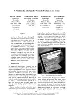
Figure 1: Logical flow of instructions.
algorithm without requiring any knowledge of the underly-
ing hardware [14]. Apart from the introduction of architec-
tural constructs and bit-level operations, the only significant
difference between ANSI-C and Handel-C is the introduc-
tion of the par construct. All statements within a par block
runinparallel.
Handel-C provides a good level of abstraction from hard-
ware design. However, its textual nature makes the data flow
in a parallel design difficult to understand. Figure 1 shows
that there is almost no visual difference between sequential
and parallel codes. This is common to all text-based HDLs.
The increased ability to concentrate on algorithm devel-
opment comes at a cost: loss of control over details such as
control flow; Handel-C builds an implied state machine to
control the data processors.
Another approach is the hardware compiler which takes
all the hardware design decisions except data-type lengths
away from the designer. This approach has been taken by SA-
C[15, 16]andMATCH[17].
SA-C incorporates common image processing functions
such as array summing for histograms and window loops.
It exploits parallelism primarily through loop unrolling and
low-level pipelining.
These systems take all control away from the designer.
They can achieve real-time operation using an offline de-
sign model. However they can only optimise an algorithm
through pipelining the sequential algorithm.
While many image processing algorithms are inherently
parallel, they are commonly expressed serially, for imple-
mentation on a serial processor. For example a filter is par-
allel in its specification, but is normally implemented as
loops. Most image processing applications involve several
steps which can each run concurrently as pipelined processes.
It is therefore desirable to have a development tool which al-
lows this parallelism to be captured at an appropriate level of
abstraction.
3. CURRENT APPROACH
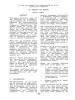
WhenimplementingalgorithmsonanFPGAwehaveused
the design flow shown in Figure 2.
Most of the effort in following this path is in the first
step: mapping an algorithm into a form suitable for FPGA
Develop algorithm
C/Matlab
Map algorit hm
to hardware
Implement design
in HDL
Compile
design
Place & route
on target device
Verify implementation
on target device
Behavioural and
functional simulation
Speed/resource
optimisation
System
debug
Figure 2: Image processing on FPGA design flow.
implementation, generally using a stream processing model.
The aim is to make the implementation as efficient as pos-
sible, which we accomplish by coarse-gain pipelining (be-
tween operations), fine-grain pipelining (breaking up oper-
ations), combining operations into one, utilising look up ta-
bles, CORDIC functions, and redesigning a standard algo-
rithm for a single-pass implementation.
This high-level design is then implemented onto hard-
ware using a hardware language, such as Handel-C. There is
a large semantic gap between our desig n mapping and the
hardware languages used to implement the design. A high-
level language for expressing image processing algorithms in
hardware should make this gap easier to bridge. It should
(i) allow a mixture of parallel and sequential desig n;
(ii) make it clear to the designer what runs in parallel and
what forms part of a pipeline;
(iii) be able to detect when concurrent processes may access
a shared resource such as a RAM, and manage this ac-
cordingly by informing the designer and giving some
suggestions as to how to resolve the issue;
(iv) be able to handle stream, offline, and hybrid process-
ing models;
(v) include some of the common image processing func-
tions and data types as primitives. Examples include
row and pixel buffering, window filters, and look up
tables (LUT);
(vi) be intuitive and easy to use;
(vii) provide multiple views onto the design.
Currently no system incorporates all of these features, and
this paper describes a system which meets these require-
ments.
Visual design tools can aid in the specification and de-
velopment of image processing algorithms. There have been
anumberofdifferent visual image processing languages for
use on a serial computer including Khoros [18]andOpShop
[19]. There are also several general purpose visual languages
which can be used for image processing, including LabView
[20] and Simulink [21]. Khoros, LabView, and Simulink now
have extensions that allow them to be used for FPGA design,
4 EURASIP Journal on Embedded Systems
Camera interface
Data flow
Control flow
Frame buffer manager
RAM1
RAM2
Bilinear interpolation
Barrel correction
Video driver
Keyboard interface
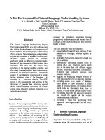
Figure 3: Architecture view of a barrel distortion correction system showing components, control, and data flows.
although this was not their original purpose. Khoros offers
a high-level view for algori thm development, but it does not
include lower-level design capabilities, as it was not designed
to support the implementation of novel image processing op-
erations. Recently other IP-based systems such as Celoxica’s
PixelStreams [22] and Xilinx’s DSP block sets [23]havebeen
developed to provide faster development time for projects
and provide similar functionality to Khoros.
These languages all follow a form of the dataflow paral-
digm where streams of data flow through a network of nodes,
each of which performs a computation on the tokens w ithin
the stream before passing the output data to the next node
[24]. It has been noted [25] that dataflow graphs (the natu-
ral visual representation of this programming paradigm) are
an effective representation for problems in digital signal pro-
cessing (DSP), both because they are a natural representa-
tion for many DSP researchers and because they expose par-
allelism in the algorithm with limited constraints on evalua-
tion order.
4. VERTIPH
As discussed in Section 3, textual languages represent con-
currency and complex scheduling poorly. We have devel-
oped VERTIPH, which incorporates a visual representation
for representing the parallel design of image processing algo-
rithms. As image processing algorithms often involve a num-
ber of largely independent processing blocks, a suitable high-
level view allows the designer to specify the data flow through
a sequence of modules. This is then augmented with lower-
level views that support the definition of par allel computa-
tions that make up the higher-level modules. Finally a re-
source and scheduling view is provided, so that the designer
can specify the timing between the operations, and access to
resources. These three are the defined views of the VERTIPH
system: the top-level architecture view,acomputational view,
and the scheduling and resource view. A comparison of VER-
TIPH with other HDLs and its required features was pre-
sented in [26]. This work expands on VERTIPH’s features
including data types and operators.
4.1. Architecture view
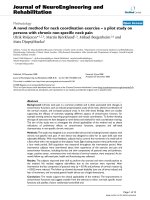
The architecture view (Figure 3) aims to provide the designer
with a perspective on the overall system. As image process-
ing algorithms are broken up into blocks which perform
very specific processing tasks, they can be developed inde-
pendently and validated using test image data. This view al-
lows the designer to construct an image processing algorithm
as several blocks that operate sequentially on the image data.
Khoros and OpShop are other systems that act at a similar
level.
The use of component blocks allows resources such as
frame buffers to be encapsulated, and related computational
processes to be logically grouped. For example, a frame
buffer component will have both an input stream and an out-
put stream, and it will contain two RAM banks. Other com-
ponents which communicate with this only see address and
data lines and the switching between memory banks can be
done within the component.
Processors which are logically related to each other
are also encapsulated. For example, a colour segmentation
and tracking algorithm detailed in [6, 7], represents each
uniquely coloured detected object as a bounding box. It
stores the bounding boxes for each colour class in a data
structure, and it incorporates processors for tracking-related
bounding boxes between frames and for calculating the po-
sition of all the bounding boxes that have been detected. The
data structure and the processors are logically related and
should therefore be kept together. This idea of encapsulation
borrows from object-orientated software engineering.
Encapsulation simplifies the sharing of data and re-
sources and it becomes clear which processor can access them
and for what purpose. It can in turn make it easier to sched-
ule these processors, as the developer does not need to re-
member all the parts of the system which are related to the
resource or data structure being used.
Hierarchical encapsulation can allow for very complex IP
blocks to be built, with one block and interfaces represent-
ing a complex system of data structures, resources, processes,
and their scheduled operations or response to events. It also
allows for a hierarchy of state machines to be used, with each
component within a component having its own state ma-
chine which may or may not then be controlled by a higher
level of the design.
The aim of the architectural view is to allow logical sep-
aration of image processing operators, to show the data flow
through the operators, and to encapsulate data and proces-
sors related to each operation.
Data types
Data types commonly encountered in image processing in-
clude 16-, 24-, and 32-bit colour, 8- and 16-bit grey scale,
and signed and unsigned integers, and fixed point numbers
of arbitrary size. The user therefore needs to be able to specify
the type of a data stream; that is, its size and format. And, as
communication in FPGAs may be by channel, by register, or
C. T. Johnston et al. 5
by wire (no storage), it is appropriate to include path-type
information in the type specification along with the more
traditional size and format information.
The data flow between high-level blocks is shown in
VERTIPH’s architecture view, so the architecture view editor
incorporates type checking to give the user feedback about
whether the data being output from one block is acceptable
as input to another. This happens as soon as a connection is
established b etween two high-level operators. The data types
of the output that drives the connection and the input that
it feeds into are immediately compared to ensure that they
are of the same type, and the user is informed if they do not
match.
Floating point numbers have not been included within
the system for several reasons: 32- or 64-bit IEEE standard
754 floating point numbers are expensive to implement in
terms of memory, circuit size, and power consumption. Im-
age processing operations generally do not require the dy-
namic range which floating point offers. Fixed point num-
bers offer better overall noise performance when the proba-
bility density function of the signals is uniform [27]. As long
as appropriate fixed point word lengths are chosen, almost all
standard image processing operations can be implemented
(with some degree of rounding error). Fixed point opera-
tions have a small footprint in hardware and lead to lower-
power consumption, thus making them the best choice for
embedded applications [27].
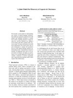
Figure 4 is the dialogue for specifying the size and range
of fixed point numbers in VERTIPH. The dialogue allows the
number of bits before and after the binary point to be altered,
using either a slider interface or a text box.
Another advantage to capturing type information is that
this information can be used to automatically align values
for ar ithmetic manipulation, and to generate a register of the
correct width to store the result. Figure 5 shows the interme-
diate registers required to implement a multiphase calcula-
tion involving a multiplication, an addition, and a subtrac-
tion. It shows that if the order of operations is changed, the
registers for the intermediate results must be altered. This is
an exacting task, and—if it is performed by the designer—a
fruitful source of errors, but the availability of type informa-
tion in VERTIPH makes it possible to eliminate the errors by
calculating the register sizes automatically.
Specialised operators
Window filters are a very common low-level image process-
ing operator. There are several forms that a window operator
can take in hardware [28], and they need to be tailored to
the application. Therefore a design wizard for constructing
operators of this type has been developed for VERTIPH.
As in other fields, certain patterns are found repeatedly
in the design of image processing systems. Each application
shares some properties with other applications, and each ap-
plication has some unique par ameters. We have therefore de-
signed VERT IPH to allow new patterns to be incorporated
into the language as wizards. The window operator is simply
the first of these.
Data Type Editor
Data Type
S7.3
Step Size
0.125
Range
8.0:7.875
Figure 4: Fixed point data type editor.
S4 U5 + U6 U4
S9
+
U6
S10
S4 U5 + U6 U4
S9
S10
S10
S Signed
U Unsigned
99bits
Figure 5: Different temporary register sizes depending on arith-
metic order.
4.2. Computational view
Developers who never design their own algorithms can use
the architecture view’s editor to assemble predefined library
modules into a high-level overview like the one shown in
Figure 3. This is similar to the way that other IP-based sys-
tems such as Celoxica’s PixelStreams and Xilinx’s DSP block
sets operate.
However, to allow developers to design their own opera-
tions and to help with buffering, pipeline priming, and syn-
chronisation, a lower level timing view is needed. The com-
putational view aims to improve the visualisation of the con-
current aspects of the low-level computations. To accomplish
this we have modified the Gantt chart notation [29]which
was designed as a visual tool to highlight the temporal re-
lationships and dependencies between phases in large con-
struction projects, and thus make it easy to schedule time-
critical activities. In this notation, time flows from left to
right, so Figure 6(a) shows a sequential set of operations; op-
eration A is followed by operation B,whichisfollowedby
operation C.InFigure 6(b), the operations occur concur-
rently, and in Figure 6(c) they are pipelined. This representa-
tion is an abbreviation of Figure 6(d) which explicitly shows
the parallel repeating processes, the passage of data from one
to the other, and that each process is active in succeeding
phases.
Of course, these basic types can be used together as
shown in Figure 7, which is the pipeline for row process-
ing used by the barrel distortion algorithm [5]. This figure
also shows the if -andwhile-controlstructuresprovidedby
VERTIPH, which are based on the control structures used in
Nassi-Shneiderman diagrams [30]. The top bar displays the
6 EURASIP Journal on Embedded Systems
AB C
Time
Concurrency
(a)
A
B
C
(b)
A
B
C
(c)
A
B
C
A
B
C
A
B
C
(d)
Figure 6: Process representations: (a) sequential, (b) parallel, (c) pipelined, (d) actual pipeline structure.
While (true)
If (videoscanX
== visiblecols)
xc
xc
sx
xc x
y +1
y
sy +2y +1
sy
Shared
register
Register modified by
more than one process
Registered
operation
Two-cycle
operation
Unregistered
operation
Outputs to
next block
Elseif (video
== visible)
xadd
x
sqrd sx
sy
k
y
Kru
Clock cycle
Interpolated LUT mag
3
Correctxmx
Correctymy
Operators
xadd: x +1
sqrd: sx +2x +1
Kru: ( sx + sy)
k
Correctx:mag
x
Correcty:mag
y
Figure 7: Low-level view of Barrel distort ion block showing control functions, timing, and operation representation. Note that text in dashed
boxes are comments added to the figure for clarification; they do not form part of the language.
control expression for the structure, with the vertical bar en-
closing the processors controlled. This pipeline view graphi-
cally conveys to the developer the time required to prime and
flush the pipeline.
Operations can b e registered or unregistered with unreg-
istered operations having to be fed into a register before a
clock cycle can finish. To save space on the screen only the
operation or register name is shown, an operations key has
the instructions for the block in a C-type syntax. This view
shows the same information as a textual language but the lay-
out makes the structure of the algorithm easier to visualise.
For example, it is easy to see that the x value must be offset
by 3 before it is used in the calculation of the undistorted x
value. Additional visual linkage between the operations and
the key can be provided by highlighting the operation in the
key when the mouse is moved over the corresponding box,
and vice versa.
The language should, where possible, automatically gen-
erate structures to handle pipeline priming, stalling, and
flushing and it should prompt developers when their design
might be using values from a different stage of the pipeline.
4.3. Resource and scheduling view
In an embedded image processing system using FPGAs there
are a large number of processors competing for access to a
limited number of resources. There are also processors which
can only run after certain events have occurred, such as an
external trigger or another processor finishing. These com-
peting and cooperative processors need to be managed and
C. T. Johnston et al. 7
Field retrace
Ver ti cal re tr ace
Vertical blanking Field retrace
Frame
0
1
Frame
1
1
RAM0
Write to
frame buffer
RAM1
Read from
frame buffer
Histogram0
Write to
histogram
Histogram1
Read from
histogram
Frame
0
2
Frame
1
2
RAM1
RAM0
Histogram1
Reset to
0
Histogram0
Swap banks
Figure 8: Timing of processes and resources used for a streamed
histogram function.
scheduled. VERTIPH facilitates resource sharing by encap-
sulating resources and the processes that act on them, so that
the processes can be scheduled. The resource and scheduling
view also allows for both global scheduling for processors and
for local scheduling within components.
To help the designer avoid resource conflicts such as two
parallel processes accessing an external RAM at the same
time, a resource usage v iew is incorporated. This view works
like standard Gantt software packages and identifies when re-
sources are used more than once in a time period. The view
can then suggest changes in the ordering of events. In the case
of a multiprocess design, this would involve either modify-
ing start conditions for processes (to ensure they do not run
together) or using semaphores or other similar mechanisms
to arbitrate access to the resource. For a time-critical design
such as stream processing from a video camera, the blocking
approach is not desirable as it can cause data to be lost, such
as when writing from a pixel stream to a frame buffer. Fortu-
nately, blanking periods or pixel buffering can often be used
to allow changes in the scheduling of competing processes.
This view can also help in the scheduling of processes which
run only at specific times—for example, when a new frame is
received—or for identifying where caching of pixels would be
more appropriate than memory access, such as when a RAM
access occurs when another process is using the RAM and no
rescheduling is possible.
One example of this type of resource conflict can occur
when a histogram is being constructed and displayed. It is de-
sirable to construct the histogram while the video stream is
buffered into one RAM. At the same time, in a different clock
domain, both the last full image and its histog ram are being
processed or displayed. Keeping one of these processes from
trying to write to one RAM while the other is reading can
be accomplished with a simple condition test. The problem
occurs due to the need to reset the histogram values in each
bin before the histogram construction algorithm is run, as
shown in Figure 8. While this requires a more complex pass-
ing of control of resources from process to process, it can also
lead to error.
5. DISCUSSION
This work has identified several existing languages which are
used for image processing on FPGAs, and commented on
both their benefits and limitations.
A new visual language, VERTIPH, has been presented.
VERTIPH makes sequential, concurrent, and pipelined op-
erations clear to the developer. It also breaks the design pro-
cess into three parts to aid in its implementation. VERTIPH
includes a block-level architecture view similar to many
other DSP block set systems; a computational view based on
Nassi-Shneiderman diagrams that expresses the operations
required in each block; and a resource and scheduling view
to aid in the development of the complex state machines that
are required to respond to events and to avoid resource con-
tention between processors. At present the block-level design
view and data-type implementation are nearing completion,
with the computational and scheduling views still to be im-
plemented.
VERTIPH is only one of several approaches that can be
taken when developing image processing systems on FPGAs;
it is a step towards better tools and methodologies that w ill
make FPGAs more usable and useful for embedded image
processing applications.
REFERENCES
[1] J. Villasenor and B. Hutchings, “The flexibility of configurable
computing,” IEEE Signal Processing Magazine, vol. 15, no. 5,
pp. 67–84, 1998.
[2] R.J.Offen, VLSI Image Processing, Collins, London, UK, 1st
edition, 1985.
[3]V.M.BoveJr.,M.M.Lee,Y M.Liu,C.M.McEniry,T.M.
Nwodoh, and J. M. Watlington, “Media processing with field-
programmablegatearraysonamicroprocessor’slocalbus,”in
Media Processors 1999, vol. 3655 of ProceedingsofSPIE-The
International Society for Optical Engineering, pp. 14–20, San
Jose, Calif, USA, January 1999.
[4] C. T. Johnston, K. T. Gribbon, and D. G. Bailey, “Implement-
ing image processing algorithms on FPGAs,” i n Proceedi ngs of
the 11th Electronics New Zealand Conference (ENZCon ’04),pp.
118–123, Palmerston North, New Zealand, November 2004.
[5] K.T.Gribbon,C.T.Johnston,andD.G.Bailey,“Areal-time
FPGA implementation of a barrel distortion correction algo-
rithm with bilinear interpolation,” in Proceedings of Image and
Vision Computing New Zealand (IVCNZ ’03), pp. 408–413,
Massey University, Palmerston North, New Zealand, Novem-
ber 2003.
[6] C. T. Johnston, D. G. Bailey, and K. T. Gribbon, “Optimi-
sation of a colour segmentation and tracking algorithm for
real-time FPGA implementation,” in Proceedings of Image and
Vision Computing Conference New Zealand (IVCNZ ’05),pp.
422–427, Dunedin, New Zealand, November 2005.
[7] C. T. Johnston, K. T. Gribbon, and D. G. Bailey, “FPGA based
remote object tracking for real-time control,” in Proce edings o f
International Conference on Sensing Technology (ICST ’05),pp.
66–72, Palmerston North, New Zealand, November 2005.
[8]K.T.GribbonandD.G.Bailey,“Anovelapproachtoreal-
time bilinear interpolation,” in Proceedings of 2nd IEEE Inter-
national Workshop on Electronic Design, Test and Applications
(DELTA ’04), pp. 126–131, Perth, Australia, January 2004.
8 EURASIP Journal on Embedded Systems
[9] IEEE Standard Verilog Hardware Description Language, vis-
ited on August 2004, />html
[10] J. Bhasker, AVHDLPrimer, Prentice-Hall, Englewood Cliffs,
NJ, USA, 3rd edition, 1999.
[11] Brigham Young University, JHDL, visited on 21 February
2005, www.jhdl.org.
[12] P. Bellows and B. Hutchings, “JHDL-an HDL for reconfig-
urable systems,” in Proceedings of IEEE Symposium on Field-
Programmable Custom Computing Machines (FCCM ’98),pp.
175–184, Napa Valley, Calif, USA, April 1998.
[13] P. Bellows and B. Hutchings, “Designing run-time reconfig-
urable systems with JHDL,” Journal of VLSI Sig nal Processing
Systems for Signal, Image, and Video Technology, vol. 28, no. 1-
2, pp. 29–45, 2001.
[14] I. Alston and B. Madahar, “From C to netlists: hardware engi-
neering for software engineers?” Electronics and Communica-
tion Engineering Journal, vol. 14, no. 4, pp. 165–173, 2002.
[15] R. Rinker, J. Hammes, W. A. Najjar, W. Bohm, and B. Draper,
“Compiling image processing applications to reconfigurable
hardware,” in Proceedings of the IEEE International Conference
on Application-Specific Systems, Architectures and Processors,
pp. 56–65, Boston, Mass, USA, July 2000.
[16]J.Hammes,B.Rinker,W.Bohm,W.Najjar,B.Draper,and
R. Beveridge, “Cameron: high level language compilation for
reconfigurable systems,” in Proceedings of International Con-
ference on Parallel Architectures and Compilation Techniques
(PACT ’99), pp. 236–244, Newport Beach, Calif, USA, Octo-
ber 1999.
[17] P. Banerjee, N. Shenoy, A. Choudhary, et al., “A MATLAB com-
piler for distributed, heterogeneous, reconfigurable comput-
ing systems,” in Proceedings of 8th IEEE Symposium on Field-
Programmable Custom Computing Machines (FCCM ’00),pp.
39–48, Napa Valley, Calif, USA, April 2000.
[18] K. Konstantinides and J. R. Rasure, “The Khoros software
development environment for image and signal processing,”
IEEE Transactions on Image Processing, vol. 3, no. 3, pp. 243–
252, 1994.
[19] P. M. Ngan, The development of a visual language for image pro-
cessing applications, Ph.D. thesis, Computer Science, Massey
University, Palmerston North, New Zealand, 1992.
[20] National Instruments LabVIEW, visited on 16 February 2005,
www.ni.com/labview.
[21] The MathWorks, Simulink 6.1, visited on 16 Februar y 2005,
www.mathworks.com/products/simulink/.
[22] Celoxica, PixelStreams Manual, 1st ed: Celoxica, 2005.
[23] Xilinx System Generator for DSP Blockset, visited on Novem-
ber 2005, />blockset.htm
[24] J. T. Buck, Scheduling dynamic dataflow graphs with bounded
memory using the token flow model,Ph.D.thesis,ElectricalEn-
gineering and Computer Sciences, University of California,
Berkeley, Calif, USA, 1993.
[25] J. T. Buck and E. A. Lee, “Scheduling dynamic dataflow graphs
with bounded memory using the token flow model,” in Pro-
ceedings of IEEE International Conference on Acoustics, Speech
and Signal Processing (ICASSP ’93), vol. 1, pp. 429–432, Min-
neapolis, Minn, USA, April 1993.
[26] C. T. Johnston, D. G. Bailey, P. Lyons, and K. T. Gribbon, “For-
malisation of a visual environment for real time image pro-
cessing in hardware (VERTIPH),” in Proceedings of Image and
Vision Computing New Zealand (IVCNZ ’04), pp. 291–296,
Akaroa, New Zealand, November 2004.
[27] A. S. L. Bainbridge-Smith, “Real number representation for
image processing on FPGAs,” in Proceedings of Image and
Vision Computing New Zealand (IVCNZ ’05), pp. 471–475,
Dunedin, New Zealand, November 2005.
[28] K. T. Gribbon, C. T. Johnston, and D. G. Bailey, “Formalizing
design patterns for image processing algorithm development
on FPGAs,” in Proceedings of IEEE Tencon Conference, pp. 21–
24, Melbourne, Australia, November 2005.
[29] J. R. Schermerhorn, Management, John Wiley & Sons, New
York, NY, USA, 6th edition, 2001.
[30] I. Nassi and B. Shneiderman, “Flowchart techniques for struc-
tured programming,” ACM SIGPLAN Notices, vol. 8, no. 8, pp.
12–26, 1973.
C. T. Johnston is a Ph.D. candidate in in-
formation engineering at the Institute of In-
formation Sciences and Technology, Massey
University, New Zealand. He received a
Bachelor of Engineering degree with first
class honours in information and telecom-
munications engineering from Massey Uni-
versity. His research focus has been in the
area of implementing image processing al-
gorithms on FPGA hardware, concentrating
on designing a visual programming language to aid in the imple-
mentation of image processing algorithms.
D. G. Bailey has B.E. (Hons) and Ph.D. de-
grees in electrical and electronic engineer-
ing from the University of Canterbury, New
Zealand. After spending two years apply-
ing image analysis techniques to the wool
and paper industries within New Zealand,
he spent two and half years as a Visiting Re-
searcher in the Electrical and Computer En-
gineering Department, University of Cali-
fornia, Santa Barbara. In 1989, he returned
to New Zealand as a Director of the Image Analysis Unit at Massey
University. In 1998 he moved to the Institute of Information Sci-
ences and Technology where he is currently a Senior Lecturer and
Leader of the Image and Signal Processing Research Group. His
primary research interests are in the application of signal process-
ing, image analysis, and image processing techniques. One research
topic of particular interest is the implementation of imaging algo-
rithms on FPGAs.
P. Ly ons is a Senior Lecturer in the Institute
of Information Sciences and Technology at
Massey University, where he teaches com-
puter architecture and human-computer
interaction, amongst other things. He has
been involved in research into visual pro-
gramming languages for a number of years.
Although his main focus in this area has
been on general purpose programming lan-
guages, he has previously been involved in
the design of two VPLs related to electronics design, PICSIL,
a pictorial language for silicon compilation, and VISTA, a spe-
cialised language for specifying control systems for induction mo-
tors, which he designed under contract, and is now in use world-
wide.