Báo cáo hóa học: " Research Article Prerouted FPGA Cores for Rapid System Construction in a Dynamic Reconfigurable System" pot
Bạn đang xem bản rút gọn của tài liệu. Xem và tải ngay bản đầy đủ của tài liệu tại đây (1014.7 KB, 7 trang )
Hindawi Publishing Corporation
EURASIP Journal on Embedded Systems
Volume 2007, Article ID 41867, 7 pages
doi:10.1155/2007/41867
Research Article
Prerouted FPGA Cores for Rapid System Construction in
a Dynamic Reconfigurable System
Timothy F. Oliver and Douglas L. Maskell
Centre for High Performance Embedded Systems (CHiPES), School of Computer Engineering,
Nanyang Technology University, Singapore 639798
Received 28 April 2006; Revised 12 October 2006; Accepted 18 October 2006
Recommended by Marco Platzner
A method of constructing prerouted FPGA cores, which lays the foundations for a rapid system construction framework for dy-
namically reconfigurable computing systems, is presented. Two major challenges are considered: how to manage the wires crossing
a core’s borders; and how to maintain an acceptable level of flexibility for system construction with only a minimum of overhead.
In order to maintain FPGA computing performance, it is crucial to thoroughly analyze the issues at the lowest level of device detail
in order to ensure that computing circuit encapsulation is as efficient as possible. We present the first methodology that allows
a core to scale its interface bandwidth to the maximum available in a routing channel. Cores can be constructed independently
from the rest of the system using a framework that is independent of the method used to place and route primitive components
within the core. We use an abstract FPGA model and CAD tools that mirror those used in industry. An academic design flow has
been modified to include a wire policy and an interface constraints framework that tightly constrains the use of the wires that
cross a core’s boundaries. Using this tool set we investigate the effect of prerouting on overall system optimality. Abutting cores are
instantly connected by colocation of interface wires. Eliminating run-time routing drastically reduces the time taken to construct
a system using a set of cores.
Copyright © 2007 T. F. Oliver and D. L. Maskell. This is an open access article distributed under the Creative Commons Attribu-
tion License, which permits unrestricted use, distribution, and reproduction in any medium, provided the original work is properly
cited.
1. INTRODUCTION
High performance computing on FPGA is achieved by ex-
ploiting the massive inherent parallelism and by using flexi-
bility to specialize the architecture. Computing on run-time
reconfigurable (RTR) FPGA devices has the potential to pro-
vide a hig her computing performance than CPU- or DSP-
based platforms. Attaining this potential performance ad-
vantage is frustrated by configuration overheads and design
complexity. The functional density metric illustrates the cost
and benefit of a reconfigurable platform [1];
D
n
=
1
A
T
En
+
T
P
+ T
T
/n
,(1)
where the functional density D
n
is a function of silicon area
A, the time taken to perform a computing operation T
En
, the
configuration transfer time T
T
, the circuit preparation time
T
P
, and the number of compute steps between reconfigura-
tions n.
Although partial RTR reduces T
T
and improves D
n
[1],
the time taken to prepare a specialized circuit T
P
must be
taken into account. Programmatic core construction [2]and
run-time routing [3, 4], while being flexible, require a large
amount of computing bandwidth. These overheads add to
the area and configuration time, outweighing the benefit of
circuit specialization. Configuration transfer T
T
is in the or-
der of hundreds of milliseconds, whereas performing run-
time placement and routing of a core put T
P
in the order of
hundreds of seconds. Thus, T
En
needs to be reduced or n in-
creased to amortize run-time construction overheads.
Rather than fine grain management of the FPGA re-
source, many practical systems use swappable log ic units [5]
with core construction and routing being performed offline.
The overheads are reduced to T
T
and a minimal manage-
ment overhead. However, systems that assume prerouting
are u sually over-restrictive as prerouting has an impact on
a core’s performance resulting in an increased T
En
and thus
a reduction in functional density. This arises because pre-
routing places wire constr aints on the router and potentially
2 EURASIP Journal on Embedded Systems
increases congestion around interface zones. In this paper, we
introduce a framework for more efficiently constructing pre-
routed computing objects and illustrate its impact on func-
tional density.
1.1. Design complexity
Designing with FPGAs requires expert knowledge of complex
FPGA compiler tools. These tools are able to integrate IP, in
the form of source code or net lists, to simplify the design
process. The a bility to relocate cores at the binary level on
an FPGA and even between FPGAs of the same family was
demonstrated [6]. This suggests it is possible to reuse IP and
compose systems at the binary level without complex tools.
Thedevelopmentenvironmenttotakeadvantageofthisdoes
not exist.
In contrast, software development benefits from a stan-
dard programming model that defines executable objects
and how they interact. Designers use dynamic instantiation,
manipulation, and removal of execution objects without a
thought for the underlying complexity. Objects are visible
from conceptual design, through compilation and at run
time. Compilation time is reduced by incremental compila-
tion and object reuse. Packaging objects into tightly specified
and pretested components provides reuse and scalability fur-
ther accelerating the design cycle.
1.2. Core-based FPGA systems
Many previous works that focus on resource allocation and
scheduling consider the FPGA resource as a homogeneous
array of logic resource [7, 8]. The performance of commu-
nication links between cores is assumed to be unaffected by
their relative placement. Previous approaches that do con-
sider interconnection have resulted in a preparation time T
P
in the order of seconds [3, 9, 10]. It was found that a 30% to
50% performance degradation occurs when core placement
does not consider interconnection [11].
The overhead and unpredictable performance associ-
ated with run-time routing is avoided by fitting cores into
a fixed-communications framework [12–15]. Industry stan-
dard tools are used to create swappable logic units that fit
a finite region size and link to a fixed interface [12, 15]. If
a core is too large for a region then it will not fit within the
framework, and if it is smaller than the fixed region the FPGA
resource is underutilized. A slight modification to this ap-
proach allows cores to share the fixed regions [15], with cores
that share a region forced to share the communication chan-
nel.
Another approach fixes the height of a core and al-
lows flexibility in its width. Cores are placed within a one-
dimensional array and connected using a segmented bus that
runs the length of the device [12].Whilethisprovidesgood
flexibility, the bandwidth of the bus is shared between all
cores, limiting data access to computing circuits. It is neces-
sary to stretch cores vertically to maximize resource utiliza-
tion, often resulting in a performance degradation. Poor area
utilization will occur when cores do not use the full height of
the device.
One previous approach that manages the FPGA space as
a two-dimensional space uses a packet-based dynamic mesh
network str ucture with routers at each intersect and places
cores inside the mesh cells [13]. A core connects to a network
routing point via a 32-bit bus, always at its top-right corner.
A core that is larger than a mesh cell is allowed to over write
the router nodes and the network handles the forwarding of
packets around cores [13]. Although this approach is robust,
the computing performance is limited by the bandwidth of
the network which will reduce as the computing cores in-
crease in size. Rent’s law indicates that larger circuits require
a larger interconnect bandwidth. An interconnect region that
is separate from the core region does not scale with core size
[16].
The main advantage of FPGA technology is the bit-le vel
parallelism. This parallelism is maintained with a wire-rich
interconnect fabric. Cores that are starved of wire bandwidth
across their borders will not allow computing circuits to run
every cycle. Thus a framework that limits the wire-level par-
allelism will forcefully limit the overall performance of an
FPGA system. A specific system topology, having fixed re-
gions, or a one-dimensional space with a single segmented
bus, or a dynamic network on chip will only suit a particular
subset of applications.
Rather than defining a fixed system structure, we inves-
tigate what is possible within the constraints of the architec-
ture itself. In our approach, the communication bandwidth
is only limited by the ability of the automatic placement and
routing tools to make best use of the wire bandwidth avail-
able in the target FPGA architecture. Rather than restrict a
system designer, we attempt to highlight the possibilities for
domain specific system topologies to be created within a gen-
eralized FPGA architecture.
1.3. Core isolation and inter facing
Inordertoallowcorestocoexistinamedium,therehastobe
isolation to prevent interference. Additionally, for cores to be
able to communicate there has to be an interface shared be-
tween cores. Interfacing and isolation of reconfigurable cores
take significant design effort [14]. Previous prerouted core
techniques waste FPGA resource in the form of LUT buffers
[17], route-free zones [14], or by forcing cores to be the
height of a device [18]. Interface bandwidth has so far been
restricted by the choice of wire resource [18], or by forcing
signals to be locked to logic resource [14]. Recent techniques
allow flexible core height and greater intercore bandwidth
[17]. A method of inserting and removing prerouted core
configurations w ithout interrupting colocated static circuits
was described [17]. Previous practical reconfigurable FPGA
systems force interface-oriented design [17].
Typically, 80% of die area on a commercial FPGA is de-
voted to interconnect [19]. Thus, it dominates circuit delay,
area, and power. Typically, 70% of the configuration bits are
associated with the control of interconnect [20]. So it is a ma-
jor factor in the functional density metric too, as it affects the
T.F.OliverandD.L.Maskell 3
area A, execution time T
En
, and configuration t ransfer time
of a system T
T
.Thusforefficient isolation and communica-
tion there has to be a focus on wire level detail.
1.4. Heterogeneous resource
The dynamic allocation of FPGA resource, unlike memory
allocation, cannot assume a homogeneous array. FPGA de-
vices cannot be considered fine-grained or coarse-grained
but are instead multigrained, including embedded proces-
sors, arithmetical units, and memory as well as configurable
cells of different complexity. Therefore, dynamic a llocation
methods must be able to manage heterogeneous resources.
Both cores and the FPGA exhibit a heterogeneous pattern of
resources. A previous approach considers the number of fea-
sible positions a core’s pattern will match that of the FPGA
and uses this information to drive placement decisions [21].
A core that uses purely logic tiles must not overlap any RAM
tiles a nd a core that uses RAM tiles must overlap available
RAM tiles.
1.5. FPGA wire detail
Modern commercial architectures use fully buffered unidi-
rectional wires in the local routing fabric [22, 23]. Unidirec-
tional routing fabrics are superior to bidirectional wire fab-
rics [24]. We find that the typical switch box flexibility (F
s
)
[10] of commercial architectures (around 5 or 6) reduces the
impact of prerouting. Prerouted cores that use tristate lines
in Virtex and Virtex-II are only using 4% and 2%, respec-
tively, of the total available wire bandwidth (W
FPGA
), and
then only along the horizontal channel [18]. The techniques
in [17] provide only 14% of W
FPGA
for interfacing and 14%
of W
FPGA
for static connections across reconfigurable regions
in the Virtex-II architecture.
FPGA interconnects are typically constructed from a sin-
gle layout tile [24] as this simplifies design, fabrication, and
testing. Our analysis of XDL for Virtex-II and Virtex-IV
shows that the switch and wire patterns on logic tiles, RAM
tiles, clock management tiles, and IO tiles are almost iden-
tical. Wires that span more than one resource tile must be
stepped or twisted [25]. In a single-tile architecture, a wire of
length L requires exactly L wire segments on the tile to create
a complete rotation [24]. We refer to this set of L wire seg-
ments as a wire set of size L.Allwiresinasetmustdrivein
the same direction.
We observe that in a single interconnect layout tile ar-
chitecture, the placement flexibility of a post-routed core is
maintained. Isolating the resources of a core to a rectangle
creates a perimeter of length P that bisec ts P
× W
FPGA
wires.
Abutting the edges of two core rectangles colocates E
×W
FPGA
wires, where E is the length of the abutting region. The colo-
cated wires provide a means to create an interface between
the two cores. The wires appear in both cores so if their sig-
nal allocations are predefined both cores can be routed inde-
pendently. Previous investigations showed 50% more rout-
ing resource was required when locking signals to wires at
the core level [16]. We find that this improves when border-
crossing wires are used as the point of isolation. The next
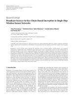
W
T
W
IN
W
IF
Figure 1: The wire policy layer splits the channel wire bandwidth
W
FPGA
into tunneling bandwidth W
T
, internal bandwidth W
IN
,and
interface bandwidth W
IF
.
section presents our proposed core constraints framework
for creating execution objects for dynamically reconfigurable
computing on FPGA.
2. CORE CONSTRAINTS FRAMEWORK
The core constraint framework has three layers: the first
layer is the resource area constraint layer, second is the in-
terface layer, and the third is the wire use policy layer. To-
gether they ensure contention-free interoperability of inde-
pendently constructed cores on the same FPGA device. It is
possible to use w ire constraints with cores constrained to any
polyomino. For simplicity, the resource constraint layer re-
stricts a core’s resource to a rectangle. The rectangle is shaped
to fit the resources that a core requires taking into account the
2D pattern of resources on the FPGA.
Thewireusepolicy defines how every wire that crosses
the borders of a core may be used. A wire policy specifies:
(i) the direction of each wire set;
(ii) the wires in a set that carry interface signals;
(iii) whether a wire set is reserved.
All wires belonging to a reserved set are considered exter-
nal and are not used within the core. The combination of
wire set direction and the border crossed determines a w ire’s
function. To maintain placement flexibility between cores
along the axis parallel to their abutting surfaces, the policy
is applied to every channel uniformly. To maintain place-
ment flexibility of cores along the axis of a wire channel all
border crossing wire sets follow a direction set by the pol-
icy. Wire sets are reserved by the policy to provide tunneling
bandwidth W
T
, for connecting nonneighboring cores. The
reservation is uniform across every wire channel in the core
to maintain a uniform tunneling bandwidth. It is proposed
that policies are developed for an FPGA architecture by de-
vice experts. The policy layer provides a mechanism to share
border crossing wires to maintain a good internal wire band-
width W
IN
and an appropriate interface bandwidth W
IF
to
the interface layer as shown in Figure 1.
The interface layer allows designers to develop prerouted
cores with compatible interfaces. An abstract interface def-
inition is an unordered list of identified signals and their
4 EURASIP Journal on Embedded Systems
direction. An interface instance assigned to a particular bor-
der edge location is a port. An assigned interface is created
by optimizing the signal ordering and mapping them to the
wires made available by the policy layer, making it suitable
for export to multiple-core developers. Abutting the ports of
two communicating cores creates a link. Therefore, an inter-
face cannot be split across more than one border edge. Links
are always point-to-point so distribution of data has to be
handled within cores. Thus the only online routing that is
required is for connecting up cores to the global networks
for signals such as clock and system-wide reset.
3. EXPERIMENTAL CORE COMPILER TOOLS
In our experimental design environment, the functionality of
a core is described using Verilog. Signal names are composed
of two parts: the signal function identifier and an interface
instance identifier. The identifier is used by the core compiler
to map the signals to an interface type and port instance. The
RTL description is compiled using an open-source synthesis
engine [26] to create an EDIF net list.
3.1. Core compiler
The input to the core compiler is an EDIF net list of FPGA
primitives mapped into basic logic cells (BLC), a set of inter-
face signals, and a set of interface definitions. The interface
definitions are described in XML and provide an absolute
wire assignment for each signal in an interface. Mapping an
interface to a set of interconnect channels each with a finite
number of available wires gives a n allocated interface, a width
along a core’s edge. The choice of allocated wires will decide
the depth to which the port reaches either side of a border.
Thus, an allocated port has a two-dimensional area, affecting
the minimum dimensions of a core. Thus, core shape plan-
ning is crucial to achieve good device utilization. The cores
are firstly shaped based upon the amount of resource re-
quired and then adjusted to fit the por t instances. The aspect
ratio of a core can be changed slightly without affecting per-
formance, after which the performance drops off rapidly. As
there are four borders and two directions across each border
there are eight possible mappings. Currently, this mapping
is performed manually to provide the maximum of control
while exploring the effect of different mappings, however we
consider this a relatively trivial task to automate.
3.2. Combined pack and place
Packing BLCs into CLBs is complicated by the fact that some
BLCs will connect to interface wires that may be at opposite
ends of a core. We therefore combine the packing and place-
ment in one step. Previous work has shown that this pro-
duces a higher quality result [27]. We have adapted the sim-
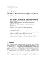
ulated annealing placement algorithm from VPR [25]. Al-
located interface definitions are used by the placer to lock
each sig nal end point to a coordinate within the core as
shown in Figure 2. This allows the handling of interface wire
Port A
Port B
Figure 2: Port signals representated in the p lacer.
placement in the placer so that BLCs connected to interface
signals are placed close to w ire end points.
3.3. Router wire constraints
We have modified the breadth first negotiating congestion
driven routing algorithm from VPR [25]. In order to support
the wire policy constraints, each node in the routing resource
graph can be marked as internal, external, input, or output.
Before routing begins the wire use policy and the assigned in-
terface definitions are used to identify and mark every node
in the graph. The router has been modified so that both a re-
source pin and a wire node can be marked as a sink or source.
During routing, internal nodes are treated in the usual way
and external nodes are never used. Input and output nodes
are only used if they are specified as sources or sinks, respec-
tively.
3.4. Run-time constructor
Port compatibility has been ensured at core compile time and
the wire use policy guarantees there will be no interference
between cores. The execution environment only has to place
the rectangle of a core so that connecting ports are correctly
aligned and ensure that cores are not overlapped. T his rapid
system constructor is referred to as a placer-connector,asit
performs both placement and connection simultaneously.
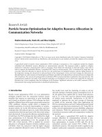
The “placer-connector” method is shown in Figure 3.
The design consists of an interface (C), several computing
cores (A), and an FIFO core (B). The interface core has to be
placed in a specific location on the FPGA as it connects to IO
tiles (Figure 3(b)). The interface core connects to the FIFO
core (B), which uses RAM tiles in the centre of the device.
The ports between interface and FIFO cores are mapped to
tunneling wires and connected using a tunneling-link core
overlaying the computing cores. The computing and inter-
face cores communicate over a sing le interface type indicated
by the dark arrows. Arrows indicate the port polarity, not
the signal direction. Several versions of the computing core
are required by the placer-connector to construct the sys-
tem. Each version of the core either has different port edge
mappings or accommodates different tile resource patterns.
Figure 3(b) shows the system created from abutted cores.
Links are created by the colocation of port wires, as shown by
the colocated arrows. The position of the right most comput-
ing core is displaced by the memory resource. A computing
T.F.OliverandD.L.Maskell 5
Tunneling link
B: FIFO core
B
A: compute cores
AA
C
C: interface core
(a)
22 logic columns 2 logic columns 22 logic columns
C
AA AA
AA AA
A
B
IO column RAM column RAM column IO column
(b)
Figure 3: (a) Prerouted cores, (b) system mapped to target FPGA
device.
core that maps around the RAM columns has been created.
The FIFO core features a data path to connect computing
cores on either side. The interface core has a second set of
interfaces to handle a second set of computing cores. This
allows the system to share the FPGA resource between two
computing arrays.
4. PERFORMANCE EVALUATION
In order to judge the impact of prerouting cores, the compiler
described above builds a system using each of the following
three approaches.
(i) Normal: merge all cores, place, and route system.
(ii) Preplaced: place each core, merge cores, route system.
(iii) Prerouted: place and route each core, merge system.
To illustrate the performance impact, we have developed
a system based on a linear array of processing elements (PEs)
and a host interface (HI), which has to be locked to IO tiles.
This is a simplified version of an FPGA accelerator for the
Smith-Waterman algorithm used for pairwise alignment of
DNA sequences with a linear gap penalty and an 8-bit dat-
apath [28]. The performance of this application is propor-
tional to the number of PEs in a linear array P.Thisisonly
HI
PE PE
PE
PE
(a)
HI
PE PE
PE PE
(b)
Post CA merge done
(c)
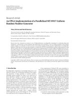
Figure 4:(a)Preroutedcoresusedin(b)a4-PEsystemconstruc-
tion, (c) mapped to the FPGA model.
effective if the subject sequence length is close to or equal to
P. Provisioning the FPGA space to share multiple arrays and
processing in parallel maintains the performance for short
sequences. This requires the ability to quickly build and scale
each linear array in response to the workload [28]. It is envis-
aged that the required system is described by a system con-
nectivity graph. Each node represents a core and the edges
represent links. The graph is automatically generated from a
request to process a subject sequence. Connectivity between
cores is defined by a single interface type for the whole sys-
tem. A single interface allocation describes the mapping of
the interface to each of the four possible directions. This de-
scription is inter preted for both polarities of a port instance
by the tools. The tools produce a list of necessary interface-
edge combinations to build the system defined by the graph.
TheHIandPEswithdifferent interface-edge combinations
are placed and routed separately and then built into arrays as
necessary. A simple 4-PE example of this system is shown in
Figure 4.
Systems of 2, 4, 6, 8, and 10 PEs were built using the
three different approaches. We have modified the architec-
ture generation of VPR to support a uniform interconnect
6 EURASIP Journal on Embedded Systems
2PEs 4PEs 6PEs 8PEs 10PEs
0
1e +7
2e +7
3e +7
Total router iterations
Normal
Preplaced
Prerouted
(a)
2PEs 4PEs 6PEs 8PEs 10PEs
0
5
10
15
20
25
30
Critical wire length (wire hops)
Normal
Preplaced
Prerouted
(b)
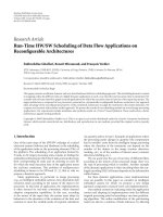
Figure 5: Comparison of (a) router iterations to build system and (b) critical path wire length as system size increases.
tile, similar to Lemieux et al. [24]. The parameters of the tar-
get FPGA architecture used were as follows: logic tiles of four
BLCs; IO tiles of four pads; interconnect channels composed
of 20 L
= 2 wire sets and 10 L = 3wiresets(W
FPGA
= 40);
and a switch box flexibility F
S
= 6[29].
The minimum wire bandwidth required for connecting
up a placed circuit (W
MIN
) is estimated by the placer [30]. We
find that congestion caused by partitioning the system into
cores and locking interface signals results in a slight increase
in W
MIN
. We use the number of maze routing neighbor ex-
pansion iterations as a measure of router effort. The number
of router iterations to compile the whole system is consis-
tently l o w f or the pr erouted approach whereas router iter-
ations for the normal and preplaced approach increase ex-
ponentially with system size (Figure 5(a)). Further m ore, the
critical path length stays constant in the prerouted approach,
whereas the critical path in the normal preplaced approaches
increases with system size (Figure 5(b)).
To illustrate the effect on functional density, consider
preplacement router iterations as proportional to T
P
and the
change in critical path length proportional to a change in T
En
.
We will assume a routing iteration takes 20 nanoseconds and
that T
T
is 50 ms. We will assume that a compute operation
takes 20 nanoseconds for the prerouted case and increases
proportional to the increase in critical path length for the
prerouted case. Using (1), for rapid reconfiguration (n less
than 10 million operations) the improvement in functional
density is 149, 280, 407, 533, and 659% for the 2, 4, 6, 8, and
10 PE systems, respectively. Above 10 mil lion operations the
performance improvement is equivalent to the change in T
En
(critical path length).
5. CONCLUSION
The aim of our work is to create a low overhead dynamic
execution environment for RTR computing on FPGA. To
achieve this, we have developed an object-oriented design,
compilation, and execution environment based on prerouted
FPGA cores, which provides a six times improvement in
functional density by allowing dynamic instantiation and
connection of cores without run-time routing.
Although interconnect architecture does not affect place-
ment flexibility, the layout of the different resources types on
modern FPGA does. Using several versions of a core provides
the run-time system with the flexibility to construc t a system
on a heterogeneous FPGA device.
There is a scope for further research into the impact of
prerouting on RTR system performance and in particular
how best to optimize interface allocations to minimize this
impact. We have presented a simple system that uses a dy-
namically linear array of processors. The geometric flexibility
provided by the techniques presented in this paper opens up
opportunities to explore many more dynamic system topolo-
gies. How these topologies best map to a particular embed-
ded computing application is open to further study.
REFERENCES
[1] M. J. Wirthlin, Improving functional density through run-time
circuit reconfiguration, Ph.D. thesis, Brigham Young Univer-
sity, Provo, Utah, USA, 1997.
[2] S. A. Guccione, D. Levi, and P. Sundararajan, “JBits: a Java
based Interface for Reconfigurable Computing,” in Proceed-
ings of 2nd Annual Militar y and Aerospace Applications of Pro-
grammable Devices and Technologies Conference (MAPLD ’99),
Laurel, Md, USA, September 1999.
[3] B. Blodget, “Pre-route assistant: a routing tool for run-time
reconfiguration,” in Proceedings of International Conference on
Field-Programmable Logic and Applications (FPL ’00), pp. 797–
800, Villach, Austria, August 2000.
[4] E. Keller, “Jroute: a run-time routing API for FPGA hardware,”
in Reconfigurable Architectures Workshop, vol. 1800 of Lecture
Notes in Computer Science, pp. 874–881, Cancun, Mexico, May
2000.
[5] G. Brebner, “The swappable logic unit: a paradigm for virtual
hardware,” in Proceedings of the 5th Annual IEEE Symposium
on FPGAs for Custom Computing Machines, pp. 77–86, Napa
Valley, Calif, USA, April 1997.
T.F.OliverandD.L.Maskell 7
[6]E.L.HortaandJ.W.Lockwood,“AutomatedMethodto
Generate Bitstream Intellectual Property Cores for Virtex FP-
GAs,” in Proceedings of International Conference on Field-
Programmable Logic and Applications (FPL ’04), vol. 3203 of
Lecture Notes in Computer Science, pp. 975–979, Antwerp, Bel-
gium, August-September 2004.
[7] K. Bazargan, R. Kastner, and M. Sarrafzadeh, “Fast template
placement for reconfigurable computing systems,” IEEE De-
sign & Test of Computers, vol. 17, no. 1, pp. 68–83, 2000.
[8] H. Walder, C. Steiger, and M. Platzner, “Fast online task place-
ment on FPGAs: free space partitioning and 2D-hashing,” in
Proceedings of International Parallel and Distributed Processing
Symposium (IPDPS ’03), p. 178, Nice, France, April 2003.
[9] J. Ma and P. Athanas, “A JBits-based incremental design en-
vironment with non-preemptive refinement for multi-million
gate FPGAs,” in Proceedings of the International Conference on
Engineering of Reconfigurable Systems and Algorithms (ERSA
’03), pp. 118–124, Las Vegas, Nev, USA, June 2003.
[10] A. Ahmadinia, C. Bobda, S. Fekete, J. Teich, and J. van der
Veen, “Optimal routing-conscious dynamic placement for re-
configurable devices,” in Proceedings of International Confer-
ence on Field-Programmable Logic and Applications (FPL ’04),
vol. 3203 of Lecture Notes in Computer Science, pp. 847–851,
Antwerp, Belgium, August-September 2004.
[11] G. Wigley, An operating system for reconfigurable computing,
Ph.D. thesis, University of South Australia, Adelaide, South
Australia, Australia, 2005.
[12] H. Kalte, M. Koester, B. Kettelhoit, M. Porrmann, and U.
R
¨
uckert, “A comparative study on system approaches for par-
tially reconfigurable architectures,” in Proceedings of the Inter-
national Conference on Engineering of Reconfigurable Systems
and Algorithms (ERSA ’04), pp. 70–76, Las Vegas, Nev, USA,
June 2004.
[13] C. Bobda, M. Majer, D. Koch, A. Ahmadinia, and J. Teich, “A
dynamic NoC approach for communication in reconfigurable
devices,” in Proceedings of International Conference on Field-
Programmable Logic and Applications (FPL ’04), vol. 3203 of
Lecture Notes in Computer Science, pp. 1032–1036, Antwerp,
Belgium, August-September 2004.
[14] E. L. Horta, J. W. Lockwood, D. E. Taylor, and D. Parlour, “Dy-
namic hardware plugins in an FPGA with partial run-time re-
configuration,” in Proceedings of 39th Design Automation Con-
ference (DAC ’02), pp. 343–348, New Orleans, La, USA, June
2002.
[15] M. Huebner, C. Schuck, and J. Becker, “Elementary block
based 2-dimensional dynamic and partial reconfiguration for
Virtex-II FPGAs,” in Proceedings 20th International Paral-
lel and Distributed Processing Symposium (IPDPS ’06),p.8,
Rhodes Island, Greece, April 2006.
[16] R. Tessier, Fast place and route approaches for FPGAs,Ph.D.
thesis, Massachusetts Institute of Technology, Cambr idge,
Mass, USA, 1999.
[17] P.Sedcole,B.Blodget,J.Anderson,P.Lysaght,andT.Becker,
“Modular partial reconfiguration in virtex FPGAs,” in Pro-
ceedings of the International Conference on Field Programmable
Logic and Applications (FPL ’05), pp. 211–216, Tampere, Fin-
land, August 2005.
[18] “Application Notes 290. Two Flows for Partial Reconfigura-
tion,” Xilinx, Version 1.2, September, 2004.
[19] A. Singh and M. Marek-Sadowska, “FPGA interconnect plan-
ning,” in Proceedings of IEEE/ACM International Workshop on
System Level Interconnect Prediction, pp. 23–30, Del Mar, Calif,
USA, April 2002.
[20] G. Brebner and D. Levi, “Networking on chip with platform
FPGAs,” in Proceedings of IEEE International Conference on
Field-Programmable Technology (FPT ’03), pp. 13–20, Tokyo,
Japan, December 2003.
[21] M. K
¨
oster, M. Porrmann, and H. Kalte, “Task placement for
heterogeneous reconfigurable architectures,” in Proceedings of
IEEE International Conference on Field-Programmable Technol-
ogy (FPT ’05), pp. 43–50, Singapore, December 2005.
[22] D. Lewis, E. Ahmed, G. Baeckler, et al., “The Stratix II logic
and routing architecture,” in Proceedings of the ACM/SIGDA
13th International Symposium on Field-Programmable Gate Ar-
rays (FPGA ’05), pp. 14–20, Monterey, Calif, USA, February
2005.
[23] “Virtex-4 Family Overview,” Xilinx, Version 1.3, 2005.
[24] G. Lemieux, E. Lee, M. Tom, and A. Yu, “Directional and
single-driver wires in FPGA interconnect,” in Proceedings o f
IEEE International Conference on Field-Programmable Technol-
ogy (FPT ’04), pp. 41–48, Brisbane, Australia, December 2004.
[25] V. Betz, J. Rose, and A. Marquardt, Architecture and CAD
for Deep-Submicron FPGAs, Kluwer Academic, Boston, Mass,
USA, 1999.
[26] S. Williams, “Icarus Verilog,” January 2006, rus
.com/eda/verilog.
[27] G. Chen and J. Cong, “Simultaneous timing driven cluster-
ing and placement for FPGAs,” in Proceedings of International
Conference on Field-Programmable Logic and Applications (FPL
’04), pp. 158–167, Antwerp, Belgium, August-September 2004.
[28] T. F. Oliver, B. Schmidt, and D. L. Maskell, “Reconfigurable
architectures for bio-sequence database scanning on FPGAs,”
IEEE Transactions on Circuits and Systems II: Express Briefs,
vol. 52, no. 12, pp. 851–855, 2005.
[29] T. F. Oliver and D. L. Maskell, “An FPGA model for developing
dynamic circuit computing,” in Proceedings IEEE International
Conference on Field-Programmable Technology (FPT ’05),pp.
281–282, Singapore, December 2005.
[30] Y. Sankar and J. Rose, “Trading quality for compile
time: Ult ra-fast placement for FPGAs,” in Proceedings of
the ACM/SIGDA 7th International Symposium on Field-
Programmable Gate Arrays (FPGA ’99), pp. 157–166, Mon-
terey, Calif, USA, February 1999.