Báo cáo hóa học: " Verification and Validation of a Fingerprint Image Registration Software" pptx
Bạn đang xem bản rút gọn của tài liệu. Xem và tải ngay bản đầy đủ của tài liệu tại đây (1.44 MB, 9 trang )
Hindawi Publishing Corporation
EURASIP Journal on Applied Signal Processing
Volume 2006, Article ID 15940, Pages 1–9
DOI 10.1155/ASP/2006/15940
Verification and Validation of a Fingerprint Image
Registration Software
Dejan Desovski,
1
Vijai Gandikota,
1
Yan Liu,
2
Yue Jiang,
1
and Bojan Cukic
1
1
Lane Department of Computer Science and Electrical Engineering, West Virginia University, Morgantown, WV 26506-6109, USA
2
Motorola Labs, Motorola Inc., Schaumburg, IL 60196, USA
Received 28 February 2005; Revised 14 September 2005; Accepted 21 October 2005
The need for reliable identification and authentication is driv ing the increased use of biometric devices and systems. Verification
and validation techniques applicable to these systems are rather immature and ad hoc, yet the consequences of the wide deployment
of biometric s ystems could be significant. In this paper we discuss an approach towards validation and reliability estimation of a
fingerprint registration software. Our validation approach includes the following three steps: (a) the validation of the source code
with respect to the system requirements specification; (b) the validation of the optimization algorithm, which is in the core of
the registration system; and (c) the automation of testing. Since the optimization algorithm is heuristic in nature, mathematical
analysis and test results are used to estimate the reliability and perform failure analysis of the image regi stration module.
Copyright © 2006 Hindawi Publishing Corporation. All rights reserved.
1. INTRODUCTION
The application of biometric devices and systems is expe-
riencing sig nificant growth, primar ily due to the increasing
need for reliable authentication and identification [1]. For
example, fingerprint identification is used at airports for se-
curing border crossing, but also in our offices as a password
replacement. Typical biometric system classifies users as gen-
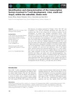
uine or imposters depending on a selected threshold. For ex-
ample, if 50 is selected as a threshold for the device whose
performance characteristics are depicted in Figure 1,allusers
with scores higher than 50 will be classified as imposters,
while those with scores less than 50 will be classified as gen-
uine. Consequently, the failures of biometric systems include
false positives (an imposter classified as a genuine) and false
negatives (a genuine user classified as an imposter).
Different algorithms [2, 3] in biometric systems have the
goal of increasing the rate of success and at the same time de-
creasing the rate of failure. Depending on the actual applica-
tion environment, the cost impact of failures might be differ-
ent. In an office setup, a rejected fingerprint (false negative)
causes the user to repeat the authentication procedure. How-
ever, if a fingerprint recognition device makes a false match
(false positive) in matters of national secur ity or criminal
court cases, the potential of grave consequences is obvious.
Most biometric applications (e.g., fingerprint, face, hand
geometry, iris scans) work with images. An image of a
biometric feature is easy to acquire. Unfortunately, studies
of image processing systems in the software reliability engi-
neering arena a re rare. One of the reasons might be the enor-
mous size of the input space. Considering a 256
× 256 black
and white image, we have 2
65536
possible inputs, excluding
any possibility of achieving input space coverage during soft-
ware testing. Another significant problem for evaluation of
imaging algorithms is defining appropriate objective metrics,
which will be indicative of the algorithm’s performance. This
difficulty arises because of the fact that it is hard to quantify
human visual perception.
Quite surprisingly, reliability studies applied to biomet-
ric systems are rare too. The most likely reason is the un-
availability of sufficiently large test data sets. Testing a bio-
metric system involves human subjects. Therefore, publicly
available datasets and data acquisition efforts must deal with
related privacy issues. Consequently, commercially available
biometric systems make no reliability claims and, if they do,
the claims may be meaningless if based on test population
sizes that do not approach statistical significance.
Our research group has been recently approached to as-
sess the quality attributes of a fingerprint image registration
software—one component of a fingerprint recognition sys-
tem. In many usage scenarios, an acquired fingerprint im-
age needs to be compared, automatically or manually, with
a stored image. The images are usually misaligned, rotated
or scaled, possibly containing different noise patterns due to
varying image acquisition circumstances. These images need
to be registered, that is, automatically aligned in the same
2 EURASIP Journal on Applied Signal Processing
0.03
0.025
0.02
0.015
0.01
0.005
0
Density
0 50 100 150 200 250
Matching scores
Genuine scores
Imposter scores
Figure 1: Score density plot of biometric device.
Source
image
Load
image
Load
image
Select
transformation
Select
landmarks
Select
landmarks
Start
regi strat ion
Registrati on
software
Register ed image
(transformed source image)
Targ et
image
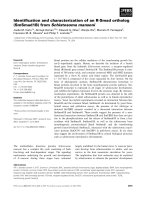
Figure 2: The image registration procedure.
position, in order to help a forensic expert in comparing the
images and verifying the match.
In order to estimate the reliability of the image registra-
tion software module we must take into account its projected
operational use and define metr ics that evaluate its success
during empirical evaluation. The implementation of the im-
age registration algorithm we study is based on the work of
Th
´
evenaz et al. We considered their paper [4] as being the
informal requirements specification document of the image
registration software. We find it rather typical for many im-
age processing systems to be developed without a software
requirements specification document. In many cases, even
software design documentation is missing or is present in
a rudimentary form, far from following the standards com-
mon in the software engineering community. This limits the
straightforward application of software verification and vali-
dation (V&V) standards. The V&V approach we adopted for
this study consists of three steps:
(a) verification of the source code with respect to the re-
quirements by performing code inspections;
(b) validation of the utilized optimization algorithms;
(c) automated reliability testing and failure analysis.
One of the reasons for adopting this approach was to fa-
miliarize ourselves with the code and the algorithms, looking
for possible implementation errors first. This familiarity, in
turn, has been very useful in the process of identifying test
cases of particular interest, that is, those that stress the per-
formance of the program and where the algorithm might fail.
This approach allowed us to reduce the size of the testing in-
put space and automate the test procedure to achieve greater
covera ge.
We presented the initial results of our research in [5].
This is an extended version of our earlier work. We expanded
the scope of the study by introducing new success metrics
used for performance analysis. We also enhanced the fail-
ure analysis methodology which is now applicable to a wide
range of image processing systems.
The rest of the paper is organized as follows. In Section 2
we define the intended use and calculate the operational pro-
file of the image registration software module. Sections 3 and
4 provide details of the validation methodology, consisting of
code inspections and analytical algorithm validation, respec-
tively. Section 5 presents test automation and the reliabilit y
estimateswewereabletoobtain.InSection 6 we describe
failure analysis, identifying why the image processing system
fails according to the defined metrics. Section 7 concludes the
paper.
2. FINGERPRINT IMAGE REGISTRATION PROCESS
Figure 2 describes the main steps in the registration process.
A forensic expert opens source and target images. He/she se-
lects the t ype of transformation to be used in the registra-
tion process. The available options are scaled rotation or affine
transformation. Depending on the transformation chosen,
the software asks the user to select two or three landmarks.
Landmarks are recognizable physical features in the image,
and the user selects them by mouse clicks. In fingerprint
images, typical features which can be selected as landmarks
are ends of ridges, ridge bifurcations, swirls, or some other
characteristic distinguishable points in the image. The same
physical features need to be marked in both the source and
the target images. User selections are marked on the screen
by corresponding cross hairs at manually selected image lo-
cations. The cross hairs are color-coded, that is, cross hairs
corresponding to the same landmark have the same color in
both the source and the target images. Once the selection of
landmarks is completed, the user initiates image registration
process, which generates a registered image.
Under the assumption that the source and the target im-
ages represent the same fingerprint, registration is success-
ful if the landmarks in the regi stered image are “sufficiently”
close to the landmarks in the target image. Successful regis-
tration enables a positive match to be established by the ex-
pert. However, we had to refine this subjective success metric.
Dejan Desovski et al. 3
In consultation with forensic fingerprint experts, we inter-
preted the success requirement into the following statement:
“the distance between the landmarks in the two images (reg-
istered and target) must be smaller than the average distance
between two ridges in the fingerprint image.” So, in order to
have the “correct” outcome, the program does not need to
produce a “perfect” alignment, but one within a reasonable
distance that will not affect the outcome of expert’s compar-
ison of the two fingerprint images. Consequently we use the
average distance between the landmarks in the registered and
target images as a measure of success. This measure has to
satisfy some specific threshold which is related to the type of
images being processed. In case of fingerprints, for example,
we identified this threshold to be the typical distance between
the ridges in the image.
Manual selection of landmarks usually introduces hu-
man error in the registration process. It is likely that se-
lected landmarks will differ by a few pixels. We expected that
this would influence the success rate and reliability of the
registration. Based on the expert’s opinion, we assumed the
following operational profile for user accuracy: positioning
within one pixel—20% of the time, within 2 pixels—70% of
the time, within 4 pixels—10% of the time.
Another aspect that could influence the success of the
registration process is the quality of the image being consid-
ered. The degree of self-similarity among the fingerprint im-
ages is very high. Therefore, blurred images might cause the
alignment optimization algorithm to end up stuck in some
local optimum. The probability of this type of failure should
decrease in sharp images that clearly depict details.
3. VERIFICATION BY SOURCE CODE INSPECTION
The registration process takes two images as inputs, the
source and the target, and performs a series of geometric
transformations minimizing the pixel differences between
them. The goal is to align the source image with the tar-
get image. Marquardt-Levenberg (ML) is a well-known gen-
eral purpose optimization algorithm [6, 7]. This algorithm is
also known to require a significant number of computations
and cause long execution times. The developers of the soft-
ware module under review decided to decrease computation
time by adopting a modified Marquardt-Levenberg (ML
∗
)
algorithm, proposed by Th
´
evenaz et al. in [4] for the spe-
cific purpose of image registration. As our team was charged
with software verification and validation, a point of concern
became the numerical optimizations of the ML
∗
algorithm.
Therefore, we paid special attention to algorithm validation
in the context of the specific usage domain (fingerprint im-
ages). Our validation effort consisted of two sets of activi-
ties: code inspection [8, 9] and algorithm validation. Code
inspections are described in this section, algorithm valida-
tion in the next section.
3.1. Specification and implementation
cross-validation
Algorithm 1 provides a brief description of the image regis-
tration procedure in the form of a pseudo-code based on the
optimized ML
∗
algorithm [4]. All the equations and sym-
bols used in Algorithm 1 correspond to those in [4]. We con-
ducted very detailed code inspections and compared the code
with the specification. One of the reasons for this activity was
the need for the members of the validation team to learn and
understand the deployed algorithms as well as their imple-
mentation. While the cost of detailed inspections is high, we
believe it was justified for our project. The consequences of
incorrect fingerprint matching in the forensic and security
applications are substantial and the prospect of litigation is
real. Consequently, eliminating the failed outcomes of the
registration algorithm is an imperative.
3.2. Summary
Based on the investigation of the specification, literature, and
code inspection, we concluded that the image registration
module is designed consistently with respect to the claimed
refere nces. The tra nsformation s it offers are linear and they
preserve the essential image features for accurate compari-
son. We realized that the software package provides imple-
mentation of the standard ML algorithm as well as the opti-
mized ML
∗
algorithm. The ML
∗
implementation conformed
to the algorithm described in [4]. The construction of the B-
spline model as well as the pyramidal approach have a so-
phisticated theoretical basis presented in [10–13]. Through
code inspections we did not find any faults in the imple-
mentation. While the absence of software faults may surprise
some readers, one needs to have in mind that our team served
as an independent verification agent. Our activities were in-
tended to go beyond the verification and validation activities
performed earlier by the software development organization.
4. ALGORITHM VALIDATION
The optimization process is critical for successful image reg-
istration. A well-established optimization algorithm and a
computationally more efficient modification of the algo-
rithm are both included in the analyzed program. In the core
of the registration process is the Marquardt-Levenberg (ML)
optimization algorithm. While code analysis activities estab-
lished correct implementation, in this activity we looked into
how ML algorithm was applied, that is, what are the conse-
quences of using this particular optimization algorithm for
fingerprint image registration. Another part of this effort was
intended to validate that ML
∗
algorithm, while improving
computational efficiency, does not compromise optimization
accuracy.
4.1. ML algorithm validation
Marquardt-Levenberg (ML) method is frequently used for
optimization in nonlinear models (e.g., neural networks,
machine learning, machine vision) and has become a virtual
standard. To support this claim we note the fact given in [14],
stating that Marquardt’s original paper [15] is the third most
frequently cited paper in all the mathematical sciences.
ML is a combination of the gradient descent and the
Newton optimization method. It is based on fundamental
4 EURASIP Journal on Applied Signal Processing
ML
∗
(p, Source, Target, TransformType, ConvCriteria, λ, M)
{
(1) Converged ← Fals e;
(2) while (! Converged)
{
(3) if TransformType == “Affine”/
∗
Affine transformation
∗
/
Q
p
= AffineTransform (Target, p);
else
(4) Q
p
= HomomorphicTransform (Target, p);
(5) χ
p
← CalculateResidue (Source, Q
p
);
/
∗
Calculate residue
∗
/
(6) β
k
← CalculateBeta (χ
p
, Q
p
);
/
∗
Calculate β
k
in equation 14 using equation 16
∗
/
(7) b
kl
← CalculateAlpha (χ
p
, Q
p
, λ);
/
∗
Calculate b
kl
in equation 14 using equation 18, 19
∗
/
(8) Δ
p
← CalculateDeltaP (γ
k
, b
kl
, M,TransformType);
/
∗
Calculate δ
p
using equation 14 for minimizing 21/22
∗
/
(9) ε
← NewEpsilon (Δ
p
, p,TransformType);
/
∗
Estimate new ε using equation 22/25
∗
/
(10) UpdateLamda (λ);
(11) p
← UpdateP (ε,Source,Target,TransformType);
/
∗
Estimate new p using equation 23/26
∗
/
(12) Converged
← TestConv (ConvCriteria, p, Source, Target);
(13) if (Converged)
break;
}
}
Algorithm 1:Pseudo-codefortheML
∗
algorithm. The equations and symbols correspond to those in [4].
observation that when we are far from the solution the
parabolic assumption is wrong so it is better to step along
the steepest decent. When we are close to the solution the
Newton’s step is better.
It is important to understand that this is a heuristic nu-
merical method and that it is not optimal for any well-
defined criterion of speed or final error [7]. It represents a
well thought out optimization procedure and it works very
well in practice. In some special cases [16], the rate of con-
vergence is proved to be quadratic. ML significantly outper-
forms other nonlinear optimization methods, like gradient
descent and conjugate gradient methods, for medium sized
problems.
Also it is important to notice that ML does not neces-
sarily find the global optimum. It can become stuck in a lo-
cal optimum and it may have no ability to escape from it. If
we are interested in finding the global optimum, the starting
point of the algorithm should be made as close to the op-
timal point as possible, otherwise it might diverge to some
other local optima. The readers should note here the impor-
tance that precise placement of landmarks in the initial step
of the fingerprint image regist ration process will have in the
results of our analysis.
The only drawback of the ML method is that it requires
a matrix inversion step as part of the update, which takes
O(n
3
)time,wheren is the size of the matrix. For medium
sized problems this method will be f aster than gradient de-
scent plus momentum. However, for large problems, the cost
of matrix inversion performed in an inner l oop of the algo-
rithm eliminates the quick convergence rates gained by the
clever algorithm design.
The authors of [4, 17] proposed a modification of the ML
algorithm for image registration applications called ML
∗
.
They used domain specific knowledge and the structure of
the developed nonlinear model to reduce the number of cal-
culations required for single iteration of the algorithm.
The error measure of the source image with respect to the
target (or reference) image is defined to be the square of the
sum of the pixel intensity differences between the two images:
ε
2
=
{x}⊂R
q
Q
p
f
T
(x
− f
R
(x)
2
dx,
ε
2
=
Q
p
f
T
(x)
−
f
R
(x)
2
,
(1)
where f
R
(x) represents the intensity of the pixel at location x
of the referen ce imag e, and Q
p
{ f
T
(x)} represents the inten-
sity of a pixel which is at the same location after the transfor-
mation Q with parameter p.
Although in [4] the authors talk about affine and homo-
morphic transformations, the actual implementation under
analysis [17] contains only the affine case (with two addi-
tional subcases: translation and scaled rotation) and bilinear
transformation.
Based on our literature review of the ML method, we
concluded that the use of the ML method to obtain the op-
timal parameter p minimizing (1) is well justified. We would
Dejan Desovski et al. 5
like to mention at least the following two relevant points.
Fingerprint images are usually 256
× 256 pixels large so we
should not expect algorithm slowdown due to matrix inver-
sion. Further, precise landmarks can make initial conditions
of the optimization problem close to the optimal solution,
thus avoiding the local optima problem or the divergence of
the method.
For the bilinear case, the code uses the standard ML algo-
rithm for optimization, consequently all that was said about
the algorithm (its advantages and disadvantages) holds also
for this case. The authors of [4] proposed for the affine cases a
modification of the algorithm in order to minimize the num-
ber of needed computations. In the next section we will look
more closely into this modification.
4.2. Modified Marquardt-Levenberg algorithm
In the affine case we have the following two operators: trans-
lation operator T
b
and an affine operator A
A
defined as fol-
lows:
T
b
f (x)
=
f (x + b), A
A
f (x)
=
f (Ax) . (2)
So, the combined transformation is
Q
A,b
f (x)
=
f (Ax + b). (3)
In order to minimize (1) the t ransformation Q is first ap-
plied to the source image which is then compared with the
reference image. The authors of [4] note that optimizing (1)
in the given form requires recalculation of the vector [β
k
]and
the matrix [b
kl
]([7, equations (16) and (18)]) because they
depend on the transformation parameter p
= (A, b)
T
,which
changes from iteration to iteration.
Based on the symmetry of the particular transformation
of interest (it is equivalent to transform the source image
and compare it with the reference image, or to apply inverse
transformation to the reference image and then perform the
comparison) we can rewrite (1) for the incremental update
Δp
= (ΔA, Δb)
T
into the following equivalent forms:
Δε
2
=
Q
p+Δp
f
T
(x)
− f
R
(x)
2
,(4)
Δε
2
=
Q
Δp
f
T
(x)
− Q
−p
f
R
(x)
2
. (5)
In the affine case, minimizing equation (5)withrespect
to Δp is equivalent to setting Δp
= 0in(4) and then mini-
mizing the equation with respect to p, which corresponds to
the standard ML. However, minimizing equation (5)ismore
beneficial because the curvature matrix [b
kl
] in this case does
not depend on the previous value p and needs to be calcu-
lated only once at the parameter value Δp
= 0.Thesameis
true for the partial derivatives ∂f
T
/∂Δp
Δp=0
.
We concluded that the proposed modification is mathe-
matically sound and appropriate for the affine case due to the
symmetry of applied transformations. Although most prob-
ably the paths in the calculation of both methods will be dif-
ferent, we concluded that b oth algorithms lead to the same
optimum, espe cially in cases where the initial conditions are
close to this optimum point. Due to fast convergence of the
method we concluded that a significant disparity in the num-
ber of iterations between the two algorithms is not expected.
The heuristic and numerical nature of ML and ML
∗
methods implies that making stronger analytical claims re-
garding the similarity of their results is not possible. Empiri-
cal testing was performed to corroborate the outcome of the
analysis.
4.3. Summary
ML is the most frequently used numerical algorithm for non-
linear optimization. It has superlinear rate of convergence
observed in practice especially when the first estimate is close
to the optimal point. Because of the matrix inversion step,
which is required, it makes most sense to apply it to small or
medium sized problems. Otherwise, the time required within
each iteration grows significantly. By using pyramidal ap-
proach the authors address both issues—reducing the prob-
lem size in the beginning so that we will get closer to the op-
timum faster, as well as possibly avoiding local optima, and
also harvesting the speed of the method when we are close
to the optimal point but the problem size is increased. The
proposed ML
∗
modification for the affine case is mathemat-
ically sound and reduces the number of calculations needed.
It should give the same results as the original ML algorithm
in the fingerprint image registration application, with im-
proved computational efficiency.
However, an important conclusion of this study is that
we do not recommend the use of bilinear transformation for
identification purposes because of the possible image distor-
tion.
5. AUTOMATION OF TESTING
Subsequent to the algorithm analysis and code inspection,
we conducted functional perfor m ance tests of the image reg-
istration system. We developed a methodology to automate
the testing as well as tools for test instrumentation and result
checking. This section describes the details of the testing pro-
cess. The code used for testing was TurboReg
.java [17]made
available to us by the authors of [4]. This code is used in the
fingerprint registration software under review.
We set the following goals for the testing procedure.
(i) Study the accuracy of registration and various tr ans-
formations when different noise levels are present in
images. We call this a “normal case” test. We want to
evaluate the impact of image quality on the registra-
tion results.
(ii) Study the accuracy of registration when the above con-
ditions apply and the user errs in landmark selection.
We call this a “variant case” test. We want to evaluate
the impact of user errors on the registration results.
5.1. Test methodology
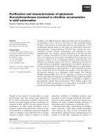
The test methodology we used is presented in Figure 3.
First, we select a source image that is to be registered. Then,
this image is transformed (scaling, rotation, affine). The
6 EURASIP Journal on Applied Signal Processing
Source
image
Image
transformation
software
Generate
variant tests
Registrati on
Analysis
tool
Reco rd
values
Targ et
image
Register ed
image
Figure 3: Testing methodology.
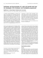
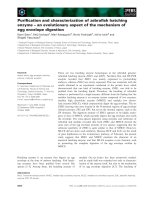
Figure 4: Image transformation software developed in MATLAB
applies various kinds of transformations and noise on the source
image to generate artificial target images.
transformed image will subsequently be used as the target
image in the registration process. Figure 4 presents the inter-
face of the image transformation tool, which we developed
for the automated generation of tests.
Next, the registration process is performed with the
source image and the generated targe t image. Registr a tion
process is monitored and its results are recorded using the au-
tomated testing software (ATS), (see Figure 5), another tool
we developed during the course of this project. Among other
functions, this tool assists testers in generating the parame-
ters for the “variant” test cases. As a reminder, the “variant
tests” are those where the user errs by introducing imprecise
landmark in the fingerprint images before submitting them
to image registration software.
As a final step we perform data analysis to investigate the
results of fingerprint image registration program, that is, the
difference between the registered and the target images (see
Figure 2).
A test on a pair of images (source and target)automat-
ically invokes one “normal test” and four “variant tests.” In
Figure 5: Automated testing software.
all tests, we conducted registration following the process de-
scribed by the software vendor. First a “normal test” which
assumes the perfect placement of image landmarks is per-
formed. Then, automated testing software (ATS) modifies
the source image landmarks by a small distance; 1, 2, or 4
pixels, in one of the 8 directions (N, NE, E, SE, S, SW, W,
NW). The simulation of user errors (user-fault-injection) al-
lows us to study how the software responds to inaccurate
initial conditions, that is, the imperfect placement of land-
marks. For each normal case (source-target image pair) this
process is repeated 4 times, with four random user-fault-
injection/registration cycles invoked automatically. The se-
lection of landmarks, in terms of the injected errors, follows
the operational profile developed earlier and described in
Section 2.
To remind readers, based on the expert’s opinion, we as-
sumed the following distribution of user accuracy: position-
ing within one pixel—20%, within 2 pixels—70%, within 4
pixels—10% of the placement attempts.
Table 1 presents some of the different transformations,
user-fault-injection, and noise techniques we used in our
testing effort.
5.2. Results
We performed tests with source images of different quality.
For each source image, we created multiple different target
images, as described above. We learned in testing that image
quality by itself did not cause the program to f ail. Only the
execution of the so-called “variant tests” resulted in a few fail-
ures. However, image quality combined with the introduced
user error and added noise had an impact on failure rates
of “variant tests.” Therefore, we present below the results of
variant tests in different test configurations.
Themeasureweusefortestoutcomesuccessdetermi-
nation is the average distance between the landmarks in the
image which is the result of the registration algorithm and
the target image. We consider the run of the registration pro-
gram to be successful if the average distance (average error
in the position of the landmarks) is smaller than the typi-
cal distance between the ridges in the finger print image. In
Dejan Desovski et al. 7
Table 1: Transformations and noise for generation of MATLAB im-
ages.
# Transform Noise Amount Done
1 Scaling (S) None 1.2 Y
2 Rotation (R) None 45 Y
3Affine (A) None 6, 0.2, 0; 1, 6, 0; 0, 0,1; Y
4 S + R None 1.2+45 Y
5 S + A None 1.2+6,0.2, 0; 1, 6, 0; 0, 0, 1; Y
6R+A None 45+6,0.2, 0; 1, 6, 0; 0, 0,1; Y
7 S+R+A None 1.2+45+6,0.2, 0; 1, 6, 0; 0,0, 1; Y
8 S Gaussian 1.2 Y
9 A Gaussian 6, 0.2, 0; 1, 6, 0; 0, 0,1; Y
10 S + R Gaussian 1.2+45 Y
11 R + A Gaussian 45 + 6, 0.2, 0; 1, 6, 0; 0, 0, 1; Y
12 S + R + A Gaussian 1.2+45+6,0.2, 0; 1, 6, 0; 0, 0, 1; Y
13 S Speckle 1.2 Y
14 A Speckle 6, 0.2, 0; 1, 6, 0; 0, 0,1; Y
15 S + R Speckle 1.2+45 Y
16 R + A Speckle 45 + 6, 0.2, 0; 1, 6, 0; 0, 0,1; Y
17 S + R + A Speckle 1.2+45+6,0.2, 0; 1, 6,0; 0,0, 1; Y
18 S Salt & pepper 1.2 Y
19 R Salt & pepper 45 Y
20 A Salt & pepper 6,0.2, 0; 1, 6, 0; 0, 0, 1; Y
21 S + R Salt & pepper 1.2+45 Y
22 S + A Salt & pepper 1.2+6,0.2, 0; 1, 6, 0; 0, 0, 1; Y
Table 2: Test results for low-quality image and scaling/rotation
transformations.
Average Average Standard Success
user error registration error deviation rate
1 1.40 0.81 100%
2 1.54 1.24 100%
4 2.56 1.74 100%
order to further study test results, we separated these results
depending on
(a) the transformation being applied in order to obtain the
target image (translation and scaling, affine);
(b) the magnitude of error introduced by the tool in the
variance tests.
The following are the results we obtained through exper-
imentation. For lower quality images, we used the threshold
of 10 pixels as the acceptable average error. In other words,
if the average distance between the landmarks in the aligned
image (the result of image registration) and the correspond-
ing target image is less than 10 pixels, the run of the regis-
tration program is successful. The distance of 10 pixels was
selected because in the fingerprint images that we used for
testing, the closest ridges were never less than 12 pixels apart.
Consequently, a fingerprint analysis expert can correctly in-
terpret an error of up to 10 pixels. The rest of this section
presents test results.
Table 3: Test results for low-quality image and affine transforma-
tions.
Average Average Standard Success
user error registration error deviation rate
1 4.34 3.38 91.18%
2 4.88 4.85 95.45%
4 6.34 7.07 89.47%
Table 4: Test results for high-quality image and affine transforma-
tions.
Average Average Standard Success
user error registration error deviation rate
1 2.90 2.34 100%
2 4.14 2.69 100%
4 3.44 2.33 91.67%
With no failures observed (Table 2), the experimentally
obtained reliability measure for low-quality images and scal-
ing/rotation transformations only is 100%. In this paper, the
reliability is defined as the proportion of program executions
that result in a successful fingerprint image registration.
Our next set of tests used the images of the same qual-
ity as above, but this time we applied affine transformations.
The results of these tests are shown in Table 3.Whenweapply
the operational profile of (0.2, 0.7, 0.1), which describes the
typical distribution of errors in the placement of the land-
marks, experimental reliability for this operational mode is
estimated to be approximately 94%.
The second set of experiments was performed with im-
ages of better quality. Same as in the operational scenarios
with lower quality images, we used the threshold of 10 pixels
as an indication of registration success. The following is the
list of our results.
Similar to the outcome of the experiments with the low-
quality image case, image translations and rotations did not
cause any failures of the registration program. The reliability
in this operational mode was estimated to be 100%.
We also tested high-quality images in combination with
affine transformations. The results of these tests are shown
in Tab le 4. By applying the operational profile of (0.2, 0.7,
0.1) as weighting factors in the linear combination of suc-
cess rates from Table 4, experimental reliability for this oper-
ational mode is approximately 99.17%.
6. FAILURE ANALYSIS
By using the defined metr ics for success, which were vali-
dated by the domain experts, the testing process provided
evidence supporting our hypotheses about the robust perfor-
mance of the image registration system reached in the source
code validation and algorithm validation analyses. Based on
all three steps of our methodology we identified that the
success rate of the fingerprint image registration software
module depends on the following three para meters.
8 EURASIP Journal on Applied Signal Processing
(a) User errors introduced in the selection of the landmarks.
Small errors make the optimization algorithm’s initial
state very close to the optimal solution, thus reducing
the possibility of getting trapped in a local optimum.
(b) The types of transformat i ons used in the generation of
image distortions, which mimic real-world latent fin-
gerprint images. Complex transformations, such as
affine, combined with the user errors in marking land-
marks caused several system failures. We were able to
trace these failures to the issue of self-similarity of the
fingerprint images which guided the algorithm to a
nonoptimal solution.
(c) The quality of the images, while not the determining
factor per se, had an impact on observed failures.Bet-
ter quality images provide crisper information to the
optimization algorithm which, in turn, avoids being
trapped in a local optimum.
One suggestion for improvement of the finger print reg-
istration system is to investigate the application of other op-
timization algorithms that can avoid local minima entrap-
ment at the expense of being computationally more expen-
sive. These algorithms could improve the reliability results
obtained in our exper iments.
7. CONCLUSIONS
The increased use of biometric systems requires additional
research efforts related to their reliability e stimation. How-
ever, the reliability prediction of biometric systems is not the
only open assessment problem, as verification and validation
standards for image processing systems are not well defined
either. We were asked to validate a module of a commercially
available system used in fingerprint analysis, the fingerprint
registration software. Due to concerns about proprietary in-
formation, this paper does not reveal the product identity.
However, we believe that the experiences reported here are
sufficiently generic and applicable to verification and valida-
tion of similar image registration/processing systems.
Our approach towards validation and reliability estima-
tion consisted of three steps:
(a) validation of the source code with respect to the system
requirements specification;
(b) validation of the optimization algorithm, which is in
the core of the registration system;
(c) automation of testing.
Source code verification provided evidence that the sys-
tem has been implemented right with respect to the research
paper describing its technical requirements. Further, it pro-
vided insights into the actual design of the software imple-
mentation. Through algorithm validation we were able to
draw conclusions about the expected performance of the sys-
tem. In principle, this step corresponds to requirements val-
idation step in traditional software engineering literature.
Furthermore, the outcomes of the analysis allowed us to
specify interesting test cases and operational modes that in-
dicated the limits of robustness of the system under test.
Testing provided further evidence corroborating the conclu-
sions reached in the previous steps.
We consider this study an early attempt to define pro-
cesses for the verification and validation of biometric tech-
nologies. As biometric systems continue to play increasingly
important role in user authentication, homeland security,
military and forensic applications, similar studies will be
needed to further our ability to reason about system and soft-
ware reliability prior to deployment.
REFERENCES
[1] A. K. Jain and S. Pankanti, “Automated fingerprint identifi-
cation and imaging systems,” in Advances in Fingerprint Tech-
nology,H.C.LeeandR.E.Gaensslen,Eds.,CRCPress,Boca
Raton, Fla, USA, 2nd edition, 2001.
[2] A. K. Jain, A. Ross, and S. Prabhakar, “Fingerprint matching
using minutiae and texture features,” in Proceedings of Inter-
national Conference on Image Processing (ICIP ’01), vol. 3, pp.
282–285, Thessaloniki, Greece, October 2001.
[3] S. Prabhakar, J. Wang , A. K. Jain, S. Pankanti, and R. Bolle,
“Minutiae verification and classification for fingerprint
matching,” in Proceedings of the 15th International Conference
on Pattern Recognition (ICPR ’00), vol. 1, pp. 25–29, Barcelona,
Spain, September 2000.
[4] P. Th
´
evenaz, U. E. Ruttimann, and M. Unser, “A pyramid
approach to subpixel registration based on intensity,” IEEE
Transactions on Image Processing, vol. 7, no. 1, pp. 27–41, 1998.
[5] D. Desovski, V. Gandikota, Y. Liu, Y. Jiang, and B. Cukic, “Val-
idation and reliability estimation of a fingerprint image regis-
tration software,” in Proceedings of the 15th International Sym-
posium on Software Reliability Engineering (ISSRE ’04),pp.
306–313, Bretagne, France, November 2004.
[6] W.H.Press,B.P.Flannery,S.A.Teukolsky,andW.T.Vetter-
ling, Eds., Numerical Recipes in C: The Art of Scientific Comput-
ing, Cambridge University Press, Cambridge, UK, 1988–1992.
[7] S. Roweis, “Levenberg-Marquardt Optimization,” http://www.
cs.toronto.edu/
∼roweis/notes.html.
[8] J. K. Chaar, M. J. Halliday, I. S. Bhandari, and R. Chillarege,
“In-process evaluation for software inspection and test,” IEEE
Transactions on Software Enginee ring, vol. 19, no. 11, pp. 1055–
1070, 1993.
[9] M. S. Fisher and B. Cukic, “Automating techniques for inspect-
ing high assurance systems,” in Proceedings of the 6th IEEE In-
ternational Symposium on High Assurance Systems Engineer-
ing (HASE ’01), pp. 117–126, Boco Raton, Fla, USA, October
2001.
[10] M. Unser, “Splines: a perfect fit for signal and image process-
ing,” IEEE Signal Processing Magazine, vol. 16, no. 6, pp. 22–38,
1999.
[11] M. Unser, A. Aldroubi, and M. Eden, “B-spline signal process-
ing. I. Theory,” IEEE Transactions on Signal Processing, vol. 41,
no. 2, pp. 821–833, 1993.
[12] M. Unser, A. Aldroubi, and M. Eden, “B-spline signal process-
ing. II. Efficiency design and applications,” IEEE Transactions
on Signal Processing, vol. 41, no. 2, pp. 834–848, 1993.
[13] M. Unser, A. Aldroubi, and M. Eden, “The L
2
-polynomial
spline pyramid,” IEEE Transactions on Pattern Analysis and
Machine Intelligence, vol. 15, no. 4, pp. 364–379, 1993.
[14] comp.ai.neural-nets FAQ, />neural-nets/.
Dejan Desovski et al. 9
[15] D. W. Marquardt, “An algorithm for least-squares estimation
of nonlinear parameters,” SIAM Journal on Applied Mathemat-
ics, vol. 11, pp. 431–441, 1963.
[16] N. Yamashita and M. Fukushima, “On the rate of convergence
of the Levenberg-Marquardt method,” Computing, no. [Suppl]
15, pp. 227–238, 2001.
[17] Turbo Registration plug-in, fl.ch/thevenaz/
turboreg/.
Dejan Desovski is a Ph.D. candidate in
computer science at West Virginia Uni-
versity, USA. He obtained his B.S. degree
in computer science from Ss. Cyril and
Methodius University in Skopje, Republic
of Macedonia, and his M.S. degree from
West Virginia University. His research inter-
ests include software V&V, combining for-
mal methods and testing, and software reli-
ability analysis and estimation.
Vijai Gandikota rece ived the B.E. degree
in electronics and communications engi-
neering from Andhra University, India, and
the M.S. degree in electrical engineering
from West Virginia University, and is cur-
rently pursuing the M.S. degree in com-
puter science at West Virginia University.
He is presently a software engineer with
IBM Inc. His interests are in the areas of
software design and development, software
V&V, machine learning, and fractals.
Ya n L i u rece ived th e B.S. degre e in com-
puter science from Wuhan University,
China, and the M.S. and Ph.D. degrees in
computer science from West Virginia Uni-
versity. She is currently a research scien-
tist at Motorola Labs, Motorola Inc. Her
research interests are in the areas of soft-
ware V&V, machine learning, and statistical
learning.
Yue Jiang receive d the B.S. degree in elec-
trical engineering from Changchun Tech-
nology University, China, and the M.S.
degree in computer science from West
Virginia University. She is currently a Ph.D.
student in West Virginia University. Her re-
search interests are in the areas of software
V&V, machine learning, and bioinformat-
ics.
Bojan Cukic is an Associate Professor in
the Lane Department of Computer Sci-
ence and Electrical Engineering at West Vir-
ginia University, where he also serves as a
Codirector of the Center for Identification
Technology Research. His research inter-
ests include software engineering for high-
assurance systems, fault-tolerant comput-
ing, information assurance, and biometrics.
He received a US National Science Foundation Career Award and
a Tycho Brahe Award for research excellence from NASA Office of
Safety and Mission Assurance. He received his Ph.D. degree in com-
puter science from the University of Houston.