Báo cáo hóa học: " Cosine-Modulated Multitone for Very-High-Speed Digital Subscriber Lines" potx
Bạn đang xem bản rút gọn của tài liệu. Xem và tải ngay bản đầy đủ của tài liệu tại đây (871.01 KB, 16 trang )
Hindawi Publishing Corporation
EURASIP Journal on Applied Signal Processing
Volume 2006, Article ID 19329, Pages 1–16
DOI 10.1155/ASP/2006/19329
Cosine-Modulated Multitone for Very-High-Speed
Digital Subscriber Lines
Lekun Lin and Behrouz Farhang-Boroujeny
Department of Electrical and Computer Engineering, University of Utah, Salt Lake City, UT 84112-9206, USA
Received 17 November 2004; Revised 24 June 2005; Accepted 22 July 2005
In this paper, the use of cosine-modulated filter banks (CMFBs) for multicarrier modulation in the application of very-high-speed
digital subscriber lines (VDSLs) is studied. We refer to this modulation technique as cosine-modulated multitone (CMT ) . CMT has
the same transmitter structure as discrete wavelet multitone (DWMT). However, the receiver structure in CMT is different from
its DWMT counterpart. DWMT uses linear combiner e qualizers, which typically have more than 20 taps per subcarrier. CMT, on
the other hand, adopts a receiver structure that uses only two taps per subcarrier for equalization. This paper has the following
contributions. (i) A modification that reduces the computational complexity of the receiver structure of CMT is proposed. (ii)
Although traditionally CMFBs are designed to satisfy perfect-reconstruction (PR) property, in transmultiplexing applications,
the presence of channel destroys the PR property of the filter bank, and thus other criteria of filter design should be adopted.
We propose one such method. (iii) Through extensive computer simulations, we compare CMT with zipper discrete multitone
(z-DMT) and filtered multitone (FMT), the two modulation techniques that have been included in the VDSL draft standard.
Comparisons are made in terms of computational complexity, transmission latency, achievable bit rate, and resistance to radio
ingress noise.
Copyright © 2006 Hindawi Publishing Corporation. All rights reserved.
1. INTRODUCTION
In recent years, multicarrier modulation (MCM) has at-
tracted considerable attention as a practical and viable tech-
nology for high-speed data transmission over spectrally
shaped noisy channels [1–6]. The most popular MCM tech-
nique uses the properties of the discrete Fourier transform
(DFT) in an elegant way so as to achieve a computation-
ally efficient realization. Cyclic prefix (CP) samples are added
to each block of data to resolve and compensate for chan-
nel distortion. This modulation technique has been accepted
by standardization bodies in both wired (digital subscriber
lines—DSL) [7–10] and wireless [11, 12] channels. While the
terminology discrete multitone (DMT) is used in the DSL lit-
erature to refer to this MCM technique, in wireless applica-
tions, the terminology orthogonal f requency-division multi-
plexing (OFDM) has been adopted. The difference is that in
DSL applications, MCM signals are transmitted at baseband,
while in wireless applications, MCM signals are upconverted
to a radio frequency (RF) band for transmission.
Zipper DMT (z-DMT) is the latest version of DMT that
has been proposed as an effective frequency-division duplex-
ing (FDD) method for very-high-speed DSL (VDSL) ap-
plications. Two variations of z-DMT have been proposed:
(i) synchronous zipper [13, 14] and (ii) asynchronous zipper
[15]. The synchronous zipper requires synchronization of all
modems sharing the same cable (a bundle of twisted pairs).
Asthisisfoundtoorestrictive(manymodemshavetobesyn-
chronized), it has been identified as an infeasible solution.
The asynchronous zipper, on the other hand, at the cost of
some loss in performance, requires only synchronization of
the pairs of modems that communicate with each other. The
unsynchronized modems on the same cable then introduce
some undesirable crosstalk noise. Since the asynchronous z-
DMT is the one that has been adopted in the VDSL draft
standard [16], in the rest of this paper all references to z-
DMT are with respect to its asynchronous version.
To synchronize a pair of modems in z-DMT, cyclic suffix
(CS) samples are used. Moreover, to suppress the sidelobes
of DFT filters and thus allow more effective FDD, extensions
are made to the CP and CS samples and pulse-shaping filters
are applied [15]. All these add to the system overhead, and
thus reduce the bandwidth efficiency of z-DMT.
Radio frequency interference (RFI) is a major challenge
that any VDSL modem has to deal with. RF signals generated
by amateur radios (HAM signals) coincide with the VDSL
band [3, 4]. Thus, there is a potential of interference be-
tween VDSL and HAM signals. The first solution to separate
2 EURASIP Journal on Applied Signal Processing
HAM and VDSL signals is to prohibit VDSL transmission
over the HAM bands. This solution along with the pulse-
shaping method adopted in z-DMT will solve the problem
of VDSL signals egress interference with HAM signals. How-
ever, the poor sidelobe behavior of DFT filters and also the
very high level of RFI still result in interference which de-
grades the performance of z-DMT significantly. RFI can-
cellers are thus needed to improve the performance of z-
DMT. There are a number of methods in the literature that
cancel RFI by treating the ingress as a tone with no or very
small variation in amplitude over each data block of DMT
[17–19]. Such methods have been found to be limited in per-
formance. Another method is to pick up a reference RFI sig-
nal from the common-mode component of the twisted-pair
signals and use it as input to an adaptive filter for synthe-
sizing and subtracting the RFI from the received signal [20].
This method which may be implemented in analog or digital
form can suppress RFI by as much as 20 to 25 dB [19]. Our
understanding from the limited literature available on RFI
cancellation is that a combination of these two methods will
result in the best performance in any DMT-based transceiver.
Thus, the comparisons given in the later sections of this pa-
per consider such a n RFI canceller setup for z-DMT.
Since RFI cancellation is rather difficult to implement,
there is a current trend in the industry to adopt filter-bank-
based MCM techniques. These can deal with RFI more effi-
ciently, thanks to much superior stopband suppression be-
havior of filter banks compared to DFT filters. We note that
z-DMT has made an attempt to improve on stopband sup-
pression. However, as we show in Section 6, z-DMT is still
much inferior to filter bank solutions.
Filtered multitone (FMT) is a filter bank solution that has
been proposed by IBM [21–23] and has been widely studied
recently. In order to avoid interference among various sub-
carriers, FMT adopts a filter bank with very sharp transition
bands and allocates sufficient excess bandw idth, typically in
the range from 0.05 to 0.125. This introduces significant in-
tersymbol interference (ISI) that is dealt with by using a sep-
arate decision feedback equalizer (DFE) for each subcarrier
[23]. Such DFEs are computationally very costly as they re-
quire relatively large number of feedforward and feedback
taps. Nevertheless, the advantages offered by this solution,
especially with respect to suppression of ingress RFI, has jus-
tified its application, and thus FMT has been included a s an
annex to the VDSL draft standard [16].
Cosine-modulated filter banks (CMFBs) working at
maximally decimated rate, on the other hand, are well un-
derstood and widely used for signal compression [24]. More-
over, the use of filter banks for realization of transmultiplexer
systems [24] as well as their application to MCM [25]have
been recognized by many researchers. In particular, the use
of CMFB to multicarrier data transmission in DSL channels
has been widely addressed in the literature, under the com-
mon terminology of discrete wavelet multitone (DWMT),
for example, see [25–32]. In DWMT, it is proposed that
channel equalization in each subcarrier be performed by
combining the signals from the desired band and its adja-
cent bands. These equalizers that have been referred to as
postcombiner equalizers impose significant load on the com-
putational complexity of the receiver. This complexity and
the lack of an in-depth theoretical understanding of DWMT
have kept industry lukewarm about it in the past.
A revisit to CMFB-MCM/DWMT has been made re-
cently [ 33–36]. In the first work, [33], an in-depth study
of DWMT has been performed, assuming that the channel
could be approximated by a complex constant gain over each
subcarrier band. This study, which is also intuitively sound,
revealed that the coefficients of each postcombiner equal-
izer are closely related to the underlying prototype filter of
the filter bank. Furthermore, there are only two parameters
per subcarrier that need to be adapted; namely, the real and
imaginary parts of the inverse of channel gain. In a further
study [34, 35], it was noted that by properly restructuring
the receiver, each postcombiner equalizer could be replaced
by a two-tap filter. It was also shown that there is no need
for cross-filters (as used in the postcombiner equalizers in
DWMT), thanks to the (near-) perfect reconstruction prop-
erty of CMFB. Moreover, a constant modulo blind equaliza-
tion algorithm (CMA) was developed [34, 35]. In [36], also
a receiver structure that combines s ignals from a CMFB and
a sine-modulated filter bank (SMFB) is proposed to avoid
cross-filters. This structure which is fundamentally similar
to the one in [34, 35] appr oaches the receiver design from
a slightly different angle. The complexity of CMFB/SMFB
receiver is discussed in [37] where an efficient structure is
proposed. In a further development [38], it is noted that
CMFB/SMFB can be configured for transmission of com-
plex modulated (such as QAM—quadrature amplitude mod-
ulated) signals. This is useful for data transmission over RF
channels, but is not relevant to xDSL channels w hich are fun-
damentally baseband.
In this paper, we extend the application of CMFB-MCM
to VDSL channels. The following contributions are made.
The receiver structure proposed in [34
, 35] is modified in
order to minimize its computational complexity. Moreover,
we discuss the problem of prototype filter design in trans-
multiplexer systems. We note that the traditional perfect-
reconstruction (PR) designs are not appropriate in this ap-
plication, and thus develop a near-PR (NPR) design strat-
egy. There are some similarities between our design strat-
egy and that of [39] where prototype filters are designed
for FMT. We contrast the CMFB-MCM against z-DMT and
FMT and make an attempt to highlight the relative advan-
tages that each of these three methods offer. In order to dis-
tinguish between the proposed method and DWMT, we re-
fer to it as cosine-modulated multitone (CMT). We believe
the term “cosine-modulated filter bank” (and thus CMT) is
more reflective of the nature of this modulation technique
than the term “wavelet.” The term wavelet is commonly used
in conjunction with filter banks in which the bandwidth of
each subband varies proportional to its center frequency. In
CMFB, a ll subbands have the same bandwidth. Moreover, the
modulator and demodulator blocks that we use are directly
developed from a pair of synthesis and analysis CMFB, re-
spectively. We should also acknowledge that there have been
some attempts to develop communication systems that use
L. Lin and B. Farhang-Boroujeny 3
Tran smitter Recei ve r
S
0
(n)
M
F
s
0
(z)
S
1
(n)
M
F
s
1
(z)
.
.
.
.
.
.
S
M –1
(n)
M
F
s
M –1
(z)
Synthesis
filter bank
H(z)
v(n)
z
– δ
F
a
0
(z) M
S
0
(n)
F
a
1
(z) M
S
1
(n)
F
a
M –1
(z) M
S
M –1
(n)
Analysis
filter bank
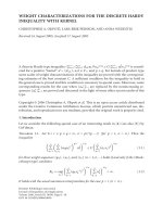
Figure 1: Block schematic of a CMFB-based transmultiplexer.
wavelets with variable bandwidths, for example, see [40]and
the references therein.
An important class of filter-bank-based transmultiplexer
systems that avoid ISI and ICI completely has been studied
recently, for example, [41, 42].SimilartoDMT,wherecyclic
prefix samples are used to avoid ISI and ICI, here also re-
dundant samples are added (e.g., through precoding) for the
same purpose. Such systems, thus, similar to DMT and FMT,
suffer from bandwidth loss/inefficiency. Moreover, since the
designed filter banks, in general, are not based on a proto-
type filter, they cannot be realized in any simple manner,
for example, in a polyphase DFT structure. Hence, they do
not seem attractive for applications such as DSL where filter
banks with a large number of subbands have to be adopted.
The rest of this paper is organized as follows. We present
an overview of CMFB-MCM/CMT in Section 2.InSection 3,
we propose a novel structure of CMT receiver which reduces
its complexity significantly compared to the previous reports
[34, 35]. In Section 4,wedevelopanNPRprototypefilterde-
sign scheme. Computational complexities and latency issues
are discussed and comparisons with z-DMT and FMT are
made in Section 5. This will be followed by a presentation of a
wide range of computer simulations, in Section 6 ,wherewe
compare z-DMT, FMT, and CMT under different practical
conditions. The concluding remarks are made in Section 7.
2. COSINE-MODULATED MULTITONE
Figure 1 presents block diagram of a CMFB-based transmul-
tiplexer system. At the transmitter, the data symbol streams
s
k
(n) are first expanded to a higher rate by inserting M −1ze-
ros after each sample. Modulation and multiplexing of data
streams are then done using a synthesis filter bank. At the
receiver, a n analysis filter bank followed by a set of decima-
tors are used to demodulate and extract the transmitted sym-
bols. The delay δ at the receiver input is required to adjust
the total delay introduced by the system to an integral mul-
tiple of M. When δ is selected correctly, channel noise ν(n)
is zero and the channel is perfect, that is, H(z)
= 1, a well-
designed transmultiplexer delivers a delayed replica of data
symbols s
k
(n) at its outputs, that is, s
k
(n) = s
k
(n −Δ), where
Δ is an integer. However, due to the channel distortion, the
recovered symbols suffer from intersymbol interference (ISI)
and intercarrier interference (ICI). Equalizers are thus used
to combat the channel distortion. As noted above, postcom-
biner equalizers that span across the adjacent subbands and
along the time axis were originally proposed for this pur-
pose [25]. Such equalizers are rather complex—typically, 20
or more taps per subcarrier are used. A recent development
[34, 35] has shown that with a modified analysis filter bank,
each subcar rier can be equalized by using only two taps. In
the rest of this section, we present a review of this modified
CMFB-based transmultiplexer and explain how such simple
equalization can be established. As noted above, we cal l this
new scheme CMT.
In CMT, the t ransmitter follows the conventional imple-
mentation of synthesis CMFB [24]. For the receiver, we resort
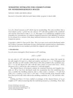
to a nonsimplified structure of the analysis CMFB. Figure 2
presents a block diagram of this nonsimplified structure for
an M-band analysis CMFB; see [24] for development of this
structure. G
k
(z), 0 ≤ k ≤ 2M − 1, are the polyphase compo-
nents of the filter bank prototype filter P(z), namely,
P(z)
=
2M−1
k=0
z
−k
G
k
z
2M
. (1)
The coefficients d
0
, d
1
, , d
2M−1
are chosen in order to
equalize the group delay of the filter bank subchannels. This
gives d
k
= e
jθ
k
W
(k+0.5)N/2
2M
for k = 0, 1, , M − 1, and d
k
=
d
∗
2M−1−k
for k = M, M +1, ,2M − 1, where θ
k
=
(−1)
k
(π/4), W
2M
= e
−j2π/2M
, ∗ denotes conjugate, and N
is the order of P(z).
Let Q
a
0
(z), Q
a
1
(z), , Q
a
2M
−1
(z) denote the transfer func-
tions between the input x(n) and the analyzed outputs
u
o
0
(n), u
o
1
(n), , u
o
2M
−1
(n), respectively. We recall from the
theory of CMFB that Q
a
k
(z) = d
k
P
0
(zW
k+0.5
2M
)fork = 0, 1,
,2M
− 1, see [24]. The CMFB analysis filters are gener-
ated by adding the pairs of Q
a
k
(z)andQ
a
2M
−1−k
(z), for k =
0, 1, , M − 1. This leads to M analysis filters [24]
F
a
k
(z) = Q
a
k
(z)+Q
a
2M
−1−k
(z), k = 0, 1, , M − 1. (2)
4 EURASIP Journal on Applied Signal Processing
x(n)
z
−1
W
−1/2
2M
z
−1
W
−1/2
2M
z
−1
W
−1/2
2M
G
0
(−z
2M
)
G
1
(−z
2M
)
G
2M−1
(−z
2M
)
2M-point
IDFT
d
0
d
1
d
2M−1
u
o
0
(n)
u
o
1
(n)
u
o
2M
−1
(n)
M
M
M
u
0
(n)
u
1
(n)
u
2M−1
(n)
.
.
.
.
.
.
.
.
.
Figure 2: The analysis CMFBstructure that is proposed for CMT.
The synthesis filters F
s
k
(z)aregivenas[24]
F
s
k
(z) = Q
s
k
(z)+Q
s
2M
−1−k
(z), k = 0, 1, , M − 1, (3)
where Q
s
k
(z) = z
−N
Q
a
k,
∗
(z
−1
) and the subscript ∗means con-
jugating the coefficients.
In a CMT transceiver, the synthesis filters F
s
k
(z)areused
at the transmitter. However, at the receiver, we resort to using
the complex coefficient analysis filters Q
a
k
(z). In the absence
of channel, and assuming that a pair of synthesis and analysis
CMFB with PR are used, we get [24]
u
k
(n) =
1
2
s
k
(n − Δ)+ jr
k
(n)
,(4)
where r
k
(n) arises because of ISI from the kth subchannel
and ICI from other subchannels. The PR property of CMFB
allows us to remove the ISI-plus-ICI term r
k
(n)andextract
the desired symbol s
k
(n−Δ) simply by taking twice of the real
part of u
k
(n). This, of course, is in the absence of channel.
The presence of channel affects u
k
(n), and s
k
(n − Δ)canno
longer be extrac ted by the above procedure.
In order to include the effect of the channel, we make
the simplifying, but reasonable, assumption that the num-
ber of subbands is sufficiently large such that the channel
frequency response H(z) over the kth subchannel can be ap-
proximated by a complex constant gain h
k
.Moreover,weas-
sume that variation of the channel group delay over the band
of transmission is negligible. Then, in the presence of chan-
nel, we obtain
u
k
(n) ≈
1
2
s
k
(n − Δ)+ jr
k
(n)
×
h
k
+ ν
k
(n), (5)
where ν
k
(n) is the channel additive noise after filtering. The
numerical results presented in Section 6 show that for a rea-
sonly large value of M, the assumption of flat channel gain
over each subcarrier is very reasonable. However, for chan-
nels with bridged taps, the group delay variation may not
be insignificant. Nevertheless, the incurred performance loss,
found through simulation, is tolerable. Clearly, the latter loss
could be compensated by adjusting the delay in each sub-
carrier channel separately. But, this would be at the cost of
significant increase in the receiver complexity which may not
be justifiable for such a minor improvement.
Considering (5), an estimate of s
k
(n) can be obtained as
follows:
s
k
(n) =
w
∗
k
u
k
(n)
=
w
k,R
u
k,R
(n)+w
k,I
u
k,I
(n),
(6)
where the subscripts R and I denote the real and imaginary
parts of the respective variables. Equation (6) shows that the
distorted received signal u
k
(n)canbeequalizedbyusinga
complex tap weig ht w
∗
k
or, equivalently, by using two real
tap weights w
k,R
and w
k,I
. If we define the optimum value
of w
∗
k
, w
∗
k,opt
, as the one that maximizes the signal-to-noise-
plus-interference ratio at the equalizer output, we find that
w
∗
k,opt
=
2
h
k
. (7)
At this point, we will make some comments about
DWMT and clarify the difference between the proposed re-
ceiver and that of the DWMT [25]. In DWMT, the analyzed
subcarrier signals that are passed to the postcombiner equal-
izersaretheoutputsofF
a
k
(z) filters, that is, 2{u
k
(n)}. Since
these outputs are real-valued, they lack the channel phase
information and, hence, a transversal equalizer with input
2
{u
k
(n)} will fall short in removing ISI and ICI. To com-
pensate for the loss of phase information, in DWMT, it was
proposed that samples of signals from kth subcarrier channel
and its adjacent subcarrier channels be combined together
for equalization. Theoretical explanation of why this method
works can be found i n [33]. Hence, the main difference be-
tween DWMT and CMT is their respective receiver struc-
tures. DWMT uses F
a
k
(z) as analysis filters. CMT, on the other
hand, uses the analysis filters Q
a
k
(z). This (minor) change
in the receiver allows CMT to adopt simple equalizers with
only two real-valued tap weights per subcarrier band while
DWMT needs equalizers that are of an order of magnitude
higher in complexity.
3. EFFICIENT REALIZATION OF ANALYSIS CMFB
Efficient implementation of synthesis CMFB using discrete
cosine transform (DCT) can be found in [24]. This will be
used at the transmitter side of a CMT transceiver. At the
L. Lin and B. Farhang-Boroujeny 5
z
−1
z
−1
z
−1
M
M
M
G
0
(−z
2
)+jz
−1
G
M
(−z
2
)
G
1
(−z
2
)+ jz
−1
G
M+1
(−z
2
)
G
M−1
(−z
2
)+jz
−1
G
2M−1
(−z
2
)
W
−0/2
2M
W
−1/2
2M
W
−(M−1)/2
2M
M-point
IDFT
C
d
0
d
1
d
M−1
u
0
(n)
u
1
(n)
u
M−1
(n)
.
.
.
.
.
.
.
.
.
Figure 3: Efficient implementation of the analysis CMFB.
receiver, as discussed above, we use a modified structure
of analysis CMFB. Thus, efficient implementations that are
available for the conventional analysis CMFB, for example,
[24], are of no use here. We develop a computationally ef-
ficient realization of the analysis CMFB by modifying the
structure of Figure 2.
At the receiver, we need to implement filters Q
a
0
(z),
Q
a
1
(z), , Q
a
M
−1
(z). Recalling that Q
a
2M
−1−k
(e
−jω
) =
[Q
a
k
(e
jω
)]
∗
and x(n) is real-valued, we argue that these filters
can equivalently be implemented by realizing Q
a
k
(z)for
k
= 0, 2, 4, ,2M − 2, that is, for even values of k only;
Q
a
1
(z), for instance, is realized by taking the conjugate of the
output of Q
a
2M
−2
(z). We thus note from Figure 2 that
Q
a
2k
(z) = d
2k
2M
−1
l=0
z
−1
W
−1/2
2M
l
G
l
−
z
2M
W
−2kl
2M
= d
2k
M
−1
l=0
z
−l
G
l
−
z
2M
+ jz
−M
G
l+M
− z
2M
W
−l/2
2M
W
−kl
M
.
(8)
Using (8) to modify Figure 2 and using the noble identi-
ties, [24], to move the decimators to the position before the
polyphase component filters, we obtain the efficient imple-
mentation of Figure 3. This implementation has a computa-
tional complexity that is approximately one half of that of the
original structure in Figure 2, assuming that the decimators
in the latter are also moved the position before the polyphase
component fi lters—here, the 2M-point IDFT in Figure 2 is
replaced by an M-point IDFT. The block C is to reorder and
conjugate the output samples, wherever needed.
The realization of Figure 3 involves implementation of M
polyphase component filters G
l
(−z
2
)+ jz
−1
G
l+M
(−z
2
), M
complex scaling factors W
−l/2
2M
,anM-point IDFT, and the
group delay compensatory coefficients d
l
. The latter coeffi-
cients may b e deleted as they can be lumped together with
the equalizer coefficients w
∗
k
.
The structure of Figure 3 should be compared with the
analysis CMFB/SMFB structure of [37]. On the basis of the
operation count (the number of multiplications and ad-
ditions per unit of time), the two structures are similar.
However, they are different in their structural details. While
Figure 3 uses an M-point IDFT with complex-valued inputs,
the CMFB/SMFB structure uses two separate transforms (a
DCT and a DST) with real-valued inputs. Therefore, a prefer-
ence of one against the other depends on the available hard-
ware or software platform on w hich the system is to be im-
plemented.
4. PROTOTYPE FILTER DESIGN
Prototype filter design is an important issue in CMT mod-
ulation. In CMFB, conventionally, the prototype filter is de-
signed to satisfy the PR property. However, in the application
of interest to this paper, the presence of channel results in a
loss of the PR property. In this section, we take note of this
fact and propose a prototype filter design scheme which in-
stead of designing for PR aims at minimizing the ISI plus ICI
and maximizing the stopband attenuation. We thus adopt an
NPR design. For this purpose, we develop a cost func tion in
which a balance between the ISI plus ICI and the stopband
attenuation is struck through a design parameter. A similar
approach was adopted in [39] for designing prototype filter
in FMT.
4.1. ISI and ICI
Referring to Figures 1 and 2, and assuming that only adjacent
subchannels overlap, in the absence of channel noise, we ob-
tain
U
o
k
(z) = z
−δ
S
k
z
M
F
s
k
(z)+S
k−1
z
M
F
s
k
−1
(z)
+ S
k+1
z
M
F
s
k+1
(z)
H(z)Q
a
k
(z),
(9)
where S
k
(z) is the z-transform of s
k
(n)andz-transforms
of other sequences are defined similarly. Substituting (3)
in (9) and noting that for k
= 0andM − 1, Q
a
k
(z)has
no (significant) overlap with Q
s
2M
−k
(z), Q
s
2M
−1−k
(z), and
6 EURASIP Journal on Applied Signal Processing
Q
s
2M
−2−k
(z), we obtain, for
1
k = 0andM − 1,
U
o
k
(z) = z
−δ
S
k
z
M
Q
s
k
(z)+S
k−1
z
M
Q
s
k
−1
(z)
+ S
k+1
z
M
Q
s
k+1
(z)
H(z)Q
a
k
(z).
(10)
We use the notation [
·]
↓M
to denote the M-fold deci-
mation. Recalling that [U
o
k
(z)]
↓M
= U
k
(z) and for arbitrary
functions X(z)andY(z), [X(z
M
)Y(z)]
↓M
= X(z)[Y(z)]
↓M
,
from (10), we obtain
U
k
(z) = S
k
(z)
z
−δ
Q
s
k
(z)H(z)Q
a
k
(z)
↓M
+ S
k−1
(z)
z
−δ
Q
s
k
−1
(z)H(z)Q
a
k
(z)
↓M
+ S
k+1
(z)
z
−δ
Q
s
k+1
(z)H(z)Q
a
k
(z)
↓M
.
(11)
Using (7), we get the estimate of S
k
(z) (the equalized signal)
as
S
k
(z) =
2
h
k
U
k
(z)
=
S
k
(z)A
k
(z)+S
k−1
(z)B
k
(z)+S
k+1
(z)C
k
(z),
(12)
where
A
k
(z) =
2
h
k
z
−δ
Q
s
k
(z)H(z)Q
a
k
(z)
↓M
,
B
k
(z) =
2
h
k
z
−δ
Q
s
k
−1
(z)H(z)Q
a
k
(z)
↓M
,
C
k
(z) =
2
h
k
z
−δ
Q
s
k+1
(z)H(z)Q
a
k
(z)]
↓M
,
(13)
and
{·}when applied to a transfer function means forming
a transfer function by taking the real parts of the coefficients
of the argument. When applied to a complex number of vec-
tor,
{·} denotes “the real part of.”
If the prototyp e filter was designed to satisfy the PR con-
dition, in the absence of the channel, we would have A
k
(z) =
z
−Δ
, B
k
(z) = 0, and C
k
(z) = 0. In the presence of the chan-
nel, these properties are lost and accordingly the ISI and ICI
powers at kth subchannel are expressed, respectively, as
ζ
k,ISI
= (a
k
− u)
T
(a
k
− u), (14)
ζ
k,ICI
= b
T
k
b
k
+ c
T
k
c
k
, (15)
where a
k
, b
k
,andc
k
are the column vectors of the coefficients
of A
k
(z), B
k
(z), and C
k
(z), respectively, and u is a column
vector with Δth element of 1 and 0 elsewhere.
The above results were given for the case when only the
adjacent bands overlap. When each subcarrier band overlaps
with more than two of its neighbor subcarrier bands, the
above results may be easily extended by defining more poly-
nomials like B
k
(z)andC
k
(z), and accordingly adding more
terms to (15).
1
In DSL applications, the sub-channels near origin (k = 0) and π (k =
M − 1) do not c arry any data [25].
4.2. The cost function
The cost function that we minimize for designing the proto-
type filter is defined as
ζ
= ζ
s
+ γ
ζ
ISI
+ ζ
ICI
, (16)
where ζ
s
is the stopband energy of the prototype filter, de-
fined below, and γ is a positive parameter which should be
selected to strike a balance between the stopband energy and
ISI plus ICI. A larger γ leads to a smaller ISI plus ICI. Here
and in the remaining discussions, for convenience, we drop
the subcarrier band index k of ζ
k,ISI
and ζ
k,ICI
.
Selecting the frequency grid
{ω
0
, ω
1
, , ω
L−1
} in the in-
terval [ω
s
, π], where ω
s
is the stopband edge of the prototype
filter, we define
ζ
s
=
1
L
L−1
l=0
P
e
jω
l
2
. (17)
We also assume that the prototype filter P(z)hasalengthof
2mM. This choice of the length follows that of the PR CMFB
[24], and is believed to be appropriate since here we design
a filter bank with NPR property. Moreover, we follow the PR
CMFB convention and design a linear-phase prototyp e filter.
This implies that
P
e
jω
l
=
e
−jω
l
(mM−0.5)
mM
−1
n=0
2p(mM + n)cos
ω
l
(n +0.5)
,
(18)
where p(n) is the nth coefficient of P(z). Rearrang ing (18),
we obtain
Cp
=
⎡
⎢
⎢
⎢
⎢
⎢
⎣
e
jω
0
(mM−0.5)
P
e
jω
0
e
jω
1
(mM−0.5)
P
e
jω
1
.
.
.
e
jω
L−1
(mM−0.5)
P
e
jω
L−1
⎤
⎥
⎥
⎥
⎥
⎥
⎦
, (19)
where C is an L
× mM matrix with the ijth element of
c
i, j
= 2cos(ω
i−1
( j − 0.5)) and p = [p(mM)p(mM +
1)
···p(2mM − 1)]
T
. Using (19), (17)mayberearranged
as
ζ
s
=
1
L
p
T
C
T
Cp. (20)
To calculate ζ
ISI
and ζ
ICI
, we note that since Q
s
k
(z)Q
a
k
(z),
Q
s
k
−1
(z)Q
a
k
(z)andQ
s
k+1
(z)Q
a
k
(z) are narrowband filters cen-
tered around the kth subcarrier band and over this band
H(z) may be approximated by the constant gain h
k
,from
(13), we obtain
a
k
= 2
q
s
k
q
a
k
↓M
, (21)
b
k
= 2
q
s
k
−1
q
a
k
↓M
, (22)
c
k
= 2
q
s
k+1
q
a
k
]
↓M
, (23)
where stands for convolution and q
s
k
and q
a
k
are the column
vectors of coefficients of z
−δ
Q
s
k
(z)andQ
a
k
(z), respectively.
L. Lin and B. Farhang-Boroujeny 7
Equation (21) may be expressed in a matrix form as
a
k
= 2
a
k
, (24)
where the matrix Q is obtained by the arranging of q
s
k
and its shifted copies in a matrix Q
o
and the decimation
of Q
o
by M in each of the columns. Noting that q
a
k
(n) =
p(n)e
j((π/M)(k+0.5)(n−N/2)+(−1)
k
(π/4))
, p(n) = p(2mM − n − 1),
and defining D as a diagonal matrix with the nth diagonal el-
ement d
n,n
= e
j((π/M)(k+0.5)(n−N/2)+(−1)
k
(π/4))
,(24)maybewrit-
ten as
a
k
= 2{QD}
p
r
p
, (25)
where p
r
is obtained by reversing the order of elements of p.
In matr ix/vector notations, p
r
= Jp where J is the antidiago-
nal matrix with the antidiagonal elements of 1. Using this in
(25), we obtain
a
k
= Ep, (26)
where E
= 2{QD}[
J
I
]andI is the identity matrix. Substi-
tuting (26)in(14), we obtain
ζ
ISI
= (Ep − u)
T
(Ep − u). (27)
Following similar steps, we obtain
ζ
ICI
= p
T
F
T
Fp, (28)
where the matrix F is constructed in the same way as E,by
replacing q
s
k
with [
q
s
k
−1
q
s
k+1
].
Now substituting (20), (27), and (28)in(16), we obtain
ζ
= (Gp −v)
T
(Gp − v), (29)
where G
=
E
F
(1/
√
γ)C
, v = [
u
0
], and 0 is a zero column vector
with proper length.
4.3. Minimization of the cost function
We note that q
s
k
,andthusG, depends on p. Hence, the cost
function (29) is fourth order in the filter coefficients p(n),
and thus its minimization is nontrivial. Rossi et al. [43]pro-
posed an iterative least-squares (ILS) minimization for a sim-
ilar problem. They formulated the same filter design problem
for the case of a PR CMFB. Adopting the method of Rossi et
al. [43], we minimize ζ by using the following procedure.
Step 1. Let p
= p
0
; an initial choice.
Step 2. Construct the matrix G using the current value of p.
Step 3. Form the normal equation Ψp
= θ,whereΨ = G
T
G
and θ
= G
T
v.
Step 4. Compute p
1
= Ψ
−1
θ.
Step 5. (p
0
+ p
1
)/2 → p
0
and go back to Step 2.
Steps 2 to 5 are run for sufficient iterations until the de-
sign converges.
Numerical examples show that this algorithm can con-
verge to a good design if the initial choice p
= p
0
and the
parameter γ are selected properly. Compared to other CMFB
prototype filter designs, this method is a ttractive because
of its relatively low computational complexity. Other meth-
ods such as those based on paraunitary property of PR filter
banks [24] are too complicated and hard to apply to filter
banks with large number of subbands; the case of interest
in this paper. Besides, such design methods are not useful
here because we are not interested in designing filter banks
with PR property. Because of these reasons, we found the ap-
proach of [43] the most appropriate in this paper, and thus
elaborate on it further.
In CMT, we are interested in very long prototype filters
whose length exceeds a few thousands. This means in the
normal equation Ψp
= θ, Ψ is a very large matrix. Hence,
Step 4 in the above procedure may be computationally ex-
pensive and sensitive to numerical errors. In our experiments
where we designed filters with length of up to 3072, using the
Matlab routine of [43], we did not encounter any numerical
inaccuracy problem. However, the design times were exces-
sively long. Since we wished to design many prototype fil-
ters, we had to find other alternative methods that could run
faster. Fortunately, we found the Gauss-Seidel method as a
good alternative.
Gauss-Seidel method is a general mathematical opti-
mization method that is applicable to variety of optimiza-
tion problems [44, 45]. It finds the optimum parameters of
interest by adopting an iterative approach. A cost function is
chosen and it is optimized by successively optimizing one of
the cost function parameters at a time, while other parame-
ters are fixed. A particular version of Gauss-Seidel reported
in [46] can be used to minimize the difference Gp
− v in
the least-squares sense without resorting to the normal equa-
tion Ψp
= θ. Moreover, an accelerated step that improves
the convergence rate of the Gauss-Seidel method has been
proposed in [46]. Through numerical examples, we found
that the accelerated Gauss-Seidel method could be used to
replace for Step 4 in the above procedure, with the advantage
of speeding up the design time by an order of magnitude or
more.
Here, we request the interested readers to refer to [46]
for details of the accelerated Gauss-Seidel method. In an ap-
pendix at the end of this paper, we have given the script of a
Matlab m-file that we have used for the design of the proto-
type filters. The prototype filter that we have used to generate
the simulation results of Section 6 is based on the following
parameters: M
= 512, m = 3, f
s
= 1.2/2M, γ = 100, and
K
= 2.
5. COMPUTATIONAL COMPLEXITY AND L ATENCY
Computational complexity and latency are two issues of
concern in any system implementation. In this section, we
present a detailed evaluation of computational complexity
8 EURASIP Journal on Applied Signal Processing
Table 1: Summary of computational complexity of z-DMT trans-
ceiver.
Function Additions Multiplications
Modulator (IFFT) M(3 log
2
M − 2) M(log
2
M − 2)
Demodulator (FFT) M(3 log
2
M − 2) M(log
2
M − 2)
FEQ 3M 3M
Table 2: Summary of computational complexity of CMT trans-
ceiver.
Function Additions Multiplications
Modulator M(1.5log
2
M +2m) M(0.5log
2
M +2m +1)
Demodulator M(3 log
2
M +2m −2) M(log
2
M +2m)
Equalizer M 2M
and latency of CMT and compare that against z-DMT and
FMT.
5.1. Computational complexity
The computational blocks involved in z-DMT and their as-
sociated oper ation counts are summarized in Table 1.The
number of operations given for each block is based on some
of the best available algorithms. In particular, we have con-
sidered using the split-radix FFT algorithm [47] for imple-
mentation of the modulator and demodulator blocks. We
have counted each complex multiplication as three real mul-
tiplications and three real additions [47]. The variable M,
here, indicates the number of subcarriers in z-DMT. The
FEQs are single-tap complex equalizers used to equalize
the demodulated data symbols. We have not accounted for
possible adaptation of the equalizers. The RFI cancellation
also is not accounted for, as it varies with the number of in-
terferers. For instance, when there is no RFI, the computa-
tional load introduced by the canceller is limited to channel
sounding for detection of RFI and this can be negligible. On
the other hand, when an RFI is detected, the system may mo-
mentarily have to take a relatively large computational load
to set up the canceller parameters. Thus, the issue here might
be that of a peak computational power load. Since account-
ing for this can complicate our analysis, we simply ignore the
complexity imposed by the RFI canceller and only comment
that this can be a burden to a practical z-DMT system.
Table 2 lists the computational blocks of a CMT
transceiver and the number of operations for each block.
Here, the modulator and demodulator are the CMFB syn-
thesis and analysis filter banks, respectively. The operation
counts of modulation are based on the efficient implemen-
tation of synthesis CMFB with DCT in [24], and the oper-
ation counts of demodulation are based on Figure 3.Two-
tap equalizers, discussed in Section 2, are used to mitigate ISI
and ICI at the demodulator outputs. Here also, we have not
accounted for possible adaptation of the equalizers. The d
k
coefficients at the output of the analysis CMFB of Figure 3
are not accounted for as they can be combined with the
Table 3: Summary of computational complexity of FMT trans-
ceiver.
Function Additions Multiplications
Modulator M(3 log
2
M +2m −4) M(log
2
M +2m −2)
Demodulator M(3 log
2
M +2m −4) M(log
2
M +2m −2)
Equalizer M(5N
f
+5N
b
− 2) 3M(N
f
+ N
b
)
equalizers. The par a meters which appeared in Table 2 are the
number of subcarriers M and the overlapping factor m; the
length of prototype filter P(z)is2mM.
Table 3 lists the computational blocks of an FMT
transceiver and the number of operations for each block.
The operation counts are based on the efficient realization in
[23]. Similar to z-DMT and CMT, here also, the adaptation
of the equalizer coefficients is not counted. M is the number
of subcarrier channels. The prototype filter length is 2mM.
N
f
and N
b
denote the number of taps in the feedforward and
feedback sections of DFE, respectively.
Adding up the number of operations given in each of
Table s 1, 2,and3, and normalizing the results by the block
length (2M for z-DMT and FMT, and M for CMT), the per-
sample complexities of z-DMT, CMT, and FMT are obtained
as
C
DMT
= 4log
2
M −1,
C
CMT
= 6log
2
M +8m +2,
C
FMT
= 4log
2
M +4m +4
N
f
+ N
b
−
7.
(30)
For all comparisons in this paper, the following parame-
ters are used. For z-DMT, we choose M
= 2048. This is con-
sistent w ith the VDSL draft standard [16] and the latest re-
ports on z-DMT [15]. For FMT, we fol low [23]andchoose
M
= 128, m = 10, N
f
= 26, and N
b
= 9. For CMT, we
experimentally found that M
= 512 and m = 3aresuffi-
cient to get very close to the best results that it can achieve.
With these choices, we obtain C
DMT
= 43, C
CMT
= 80, and
C
FMT
= 201 operations per sample. It is noted that FMT is
significantly more complex than z-DMT and CMT, and the
computational complexity of CMT is about 2 times that of
the z-DMT. However, we should note that the complexity of
z-DMT given here does not include the RFI canceller which,
as noted above, can momentarily exhibit a significant com-
putational peak lo ad, whenever a new RFI is detected.
5.2. Latency
In the context of our discussion in this paper, the latency is
defined as the time delay that each coded information sym-
bol will undergo in passing through a transceiver. In z-DMT,
the following operations have to be counted for. A block of
data symbols has to be collected in an input buffer before
being passed to the modulator. This, which we refer to as
buffering delay, introduces a delay equivalent to one block of
DMT. While the next block of data symbols is being buffered,
the modulator processes the previous block of data. This in-
troduces another block of DMT delay. We refer to this as
L. Lin and B. Farhang-Boroujeny 9
Symbol
generator
Symbol
generator
Symbol
generator
Modulator
Modulator
Modulator
NEXT coupling
FEXT coupling
Channel
Background
noise
RFI
Demodulator
Calculate
SNR
Bit
allocation
Figure 4: Simulation setup.
processing delay. The buffering and processing delay together
count for a delay of the equivalent of two blocks of DMT at
the transmitter. Following the same discussion, we find that
the receiver also introduces two blocks of DMT delay. Thus,
the total latency introduced by the transmitter and receiver
in z-DMT (or DMT, in general) is given by
Δ
DMT
= 4T
DMT
, (31)
where T
DMT
is the time duration of each z-DMT block. This
includes a block of data and the associated cyclic extensions.
We also note that the channel introduces some delay. Since
this delay is small and common to the three schemes, we ig-
nore it in all the latency calculations. We thus use the follow-
ing approximation for the purpose of comparisons:
Δ
DMT
= 4(2M + μ
cp
+ μ
cs
)T
s
, (32)
where μ
cp
and μ
cs
are the length of cyclic prefix and cyclic
suffix, respectively, and T
s
is the sampling interval which in
the case of VDSL is 0.0453 microseconds, corresponding to
the sampling frequency of 22.08 MHz.
The latency calculation of CMT is straightforward. The
delay introduced by the synthesis and analysis filter banks is
determined by the total group delay introduced by them. It is
equal to the length of the prototype filter times the sampling
interval T
s
. This results in a delay of 2mMT
s
. We should add
to this the buffering and processing delays. Since each pro-
cessing of CMT is performed after collecting a block of M
samples, the total buffering plus processing delay in a CMT
transceiver is equal to 4MT
s
. The latency of CMT is thus ob-
tained as
Δ
CMT
= (2m +4)MT
s
. (33)
The latency calculation of FMT is similar to that of CMT.
Delays are introduced by the synthesis filter bank, the analy-
sis filter bank, and the DFEs. The delay introduced by synthe-
sis and analysis filter banks is 2mMT
s
. A total buffering and
processing delay 4MT
s
should be added to this. The delay in-
troduced by the feedforward section of DFE is N
f
/2samples.
Since fractionally spaced DFEs work at the rate decimated by
M, the introduced delay is MN
f
T
s
/2. The latency of FMT is
thus
Δ
FMT
=
2m +8+
N
f
2
MT
s
. (34)
As noted in Section 5.1, we choose M
= 2048 and μ
cp
+
μ
cs
= 320 for z-DMT, M = 512 and m = 3forCMT,and
choose M
= 128, m = 10, N
f
= 26, and N
b
= 9forFMT.
These result in the latency values Δ
DMT
= 800 microseconds,
Δ
CMT
= 232 microseconds, and Δ
FMT
= 238 microseconds.
We note that the latencies of CMT and FMT are significantly
lower than that of z-DMT. This, clearly, is because of the use
of a much smaller block size M in CMT and FMT.
6. SIMULATION RESULTS AND DISCUSSION
The system model used for simulations is presented
in Figure 4. This setup accommodates NEXT (near-end
crosstalk) and FEXT (far-end crosstalk) coupling, back-
ground noise, and RFI ingress. The setup assumes that the
system is in training mode, and thus transmitted symbols are
available at the receiver. Hence, we can measure SNRs at var-
ious subcarrier bands, and accordingly find the correspond-
ing bit allocations. The symbol generator output is 4-QAM
in the cases of z-DMT and FMT, and antipodal binary for
CMT.
To make comparisons with the previous works possible,
we follow simulation parameters of [15],ascloseaspossible.
We use a transmission bandwidth of 300 kHz to 11 MHz. The
noise sources include a mix of ETSI‘A’, [48], 25 NEXT, and 25
FEXT disturbers. Transmit band allocation is also performed
according to [15].
6.1. System parameters
The number of subcarriers M and the length of the proto-
type filter 2mM are the two most important parameters in
CMT. Obviously, the system performance improves as one
10 EURASIP Journal on Applied Signal Processing
0
5
10
15
20
25
30
35
40
Bit rate (Mbps)
0 200 400 600 800 1000 1200 1400
Length of TP1 (m)
Upper bound
CMT proposed design
CMT PR design
z-DMT
FMT
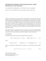
Figure 5: Comparison of bit rates of z-DMT, CMT, and FMT on
TP1 lines of different lengths.
or both of these parameters increase. However, as we may
recall from the results of Section 5, both system complexity
and latency increase with M and m.Itisthusdesirableto
choose M and m to strike a balance between the system per-
formance and complexity. Moreover, for a given pair of M
and m, the system performance is affected by the choice of
the CMFB prototype filter. An important parameter that af-
fects the performance of CMT is the stopband edge of the
prototype filter ω
s
.Theoptimumvalueofω
s
is hard to find.
On one hand, the choice of a small ω
s
is desir able as it limits
the bandwidth of each subcarrier and makes the assumption
of constant channel gain over each subband more accurate.
On the other hand, a larger choice of ω
s
improves the stop-
band attenuation of the prototype filter, and this in turn re-
duces the ICI and noise interference from the nonadjacent
subbands.Moreover,alargevalueofω
s
increases RF ingress
noise and the NEXT near the frequency band edges. Unfor-
tunately, because of the complexity of the problem and the
variety of the parameters that affect the system performance,
a good compromised choice of Mm and ω
s
could only be ob-
tained through extensive numerical tests over a wide variety
of channel setups. The details of such results will be reported
in [49]. Here, we mention the summary of observations that
we have had. The choice of M
= 512 was generally found suf-
ficient to satisfy the approximation “constant channel gain
over each subband.” With M
= 512, the choices m = 3 (thus,
a prototype filter length of 3072) and ω
s
= 1.2π/M result in
a system which behaves very close to the optimum perfor-
mance, where the optimum performance is that of an ideal
system with nonoverlapping subcarrier bands; see Figure 5.
In our study, we also explored the choices of m
= 2and
m
= 1. The results, obviously, were not as good as those of
m
= 3, however, for most cases, they were still superior to z-
DMT and FMT. Here, because of space limitation, we only
present results and compare CMT with z-DMT and FMT
when in CMT, M
= 512, m = 3andω
s
= 1.2π/M.Detailsof
other cases will be reported in [49].
For z-DMT, the number of subcarriers is set equal to
2048, following the VDSL draft standard [16]. As in [15], we
have selected the length of CP equal to 100, determined the
length of CS according to the channel group delay, and the
length of the pulse-shaping and windowing samples are set
equal to 140 and 70, respectively.
Following the parameters of [23], we use an FMT system
with M
= 128 subchannels, and a prototype filter of length
2mM,withm
= 10. The excess bandwidth α is set equal to
0.125. Per-subcarrier equalization is performed by employ-
ing a Tomlinson-Harashima precoder with N
b
= 9tapsand
a T/2-spaced linear equalizer with N
f
= 26 taps.
6.2. Crosstalk dominated channels
The DSL environment is crosstalk dominated due to
bundling of wire pairs in binder cables. Here, we consider the
performance of z-DMT, CMT, and FMT when both NEXT
and FEXT are present. Since the three modulation schemes
are frequency-division duplexed ( FDD) systems, NEXT is
significant only near the frequency band edges where there
is a change in transmit direction. FEXT, on the other hand,
affects all the transmit band.
In our simulations, NEXT and FEXT are generated ac-
cording to the coupling equations provided in [16]fora50-
pair binder cable as
PSD
NEXT
= K
NEXT
S
d
( f )
N
d
49
0.6
f
1.5
,
PSD
FEXT
= K
FEXT
S
d
( f )
H( f )
2
d
N
d
49
0.6
f
2
,
(35)
where K
NEXT
and K
FEXT
areconstantswithvaluesof8.818 ×
10
−14
and 7.999 × 10
−20
,respectively,S
d
( f )isthePSDofa
disturber, N
d
is the number of disturbers, H( f ) is the chan-
nel frequency response, and d is the channel length in meters.
Figure 6 presents SNR curves demonstrating the impact
of NEXT in degrading the performance of z-DMT, CMT, and
FMT. The results correspond to a 810 m TP1 line. The arrows
↓ and ↑ indicate downstream and upstream bands, respec-
tively.TheSNRineachsubcarrierchannelismeasuredin
the time domain by looking at the power of the residual error
after subtracting the transmitted symbols. As one would ex-
pect, there is a significant perfor mance loss in z-DMT at the
points where the t ransmission direction changes. The CMT
and FMT, on the other hand, do not show any visible degra-
dation due to NEXT. It is worth noting that the SNR results
of z-DMT match closely those reported in [15].
Another observation in Figure 6 thatrequiressomecom-
ments is that although CMT has a lower SNR compared to
z-DMT and FMT, it may achieve a h igher transmission rate
because of higher bandwidth efficiency—no cyclic extensions
or excess bandwidth.
L. Lin and B. Farhang-Boroujeny 11
0
5
10
15
20
25
30
35
40
SNR (dB)
0246810
Frequency (MHz)
z-DMT
CMT
FMT
Figure 6: SNR curves showing the impact of NEXT on z-DMT,
CMT, and FMT. Arrows indicate the direction of data transmission.
Figure 5 presents plots that compare the bit rates of z-
DMT, CMT, and FMT on TP1 lines of different lengths. Also
shown in this figure are the results of an ideal system where a
bank of ideal filters with zero tr ansition bands and a channel
with flat gain over each subband are assumed. Moreover, for
CMT, we have presented the results when a prototype filter
with PR proper ty (designed using the code given in [43]) is
used and when the design procedure of Section 4 is adopted.
As seen, CMT, even with PR design, outperforms z-DMT and
FMT for all the line lengths with a gain of 5 to 10% higher
bit rate. Moreover, CMT approaches very close to the upper
bound of the bit rate determined by the idealized system. A
design based on PR property is already within 5% of the up-
per bound. The filter design proposed in Section 4 reduces
this gap to around 2
∼ 3%. An observation in Figure 5 that
requires some comments is that the performance of FMT is
worse than that of FMT obtained in [23], especially w hen the
length of the line is larger than 1000 m. This is because we
use a different noise model than [23]. We follow [15]anduse
ETSI‘A’ as the background noise, while
−140 dBm/Hz white
Gaussian noise is used in [23].
Bit allocation for each subcarrier is done based on the
following formula [4, 50]:
b
i
= log
2
1+
SNR
i
· γ
code
Γ · γ
margin
, (36)
where SNR
i
is signal-to-noise ratio at the ith subcarrier,
γ
code
= 3 dB is the coding gain, Γ = 9.8 dB is the SNR
gap between the Shannon capacity and QAM-modulation to
achieve a BER of a pproximately 10
−7
,andγ
margin
= 6dB is
the system margin. Since in CMT data symbols are PAM, we
treat each pair of adjacent PAM symbols as one QAM symbol
and apply (36).
6.3. Channels with bridged taps
So far, the simulated subscriber loops were homogeneous
lengths of TP1 cables. Previous reports, [30], as well as our
simulation studies have show n that the group delay distor-
tion of such lines is very minimal and mostly limited to very
low and very high frequencies in the VDSL band. Nonho-
mogeneous subscriber lines with bridged taps, on the other
hand, exhibit significant group delay distortion. Hence, a
study of CMT behavior in VDSL loops with bridged taps is
essential to complete our study. We present simulation re-
sults for the five test loops that are shown in Figure 7. These
are chosen from the test loops provided in [16]. Figure 8
presents the group delays of two of these loops and also that
of a 300 m TP1 line with no bridged tap. We note that the
line without bridged tap exhibits almost no group delay dis-
tortion over most of the channel band, while as the number
of bridged taps increases, the group delay distortion also in-
creases. We also note that the fast variations of the group de-
lay at certain frequencies coincide with the points where the
magnitude gain of the channel is reduced due to signal reflec-
tion from the open-ended bridged-tap extensions. This phe-
nomenon is clearly seen by referring to Figure 9 where the
subcarrier SNRs of z-DMT, CMT, and FMT are shown for the
loop 4 “short.” The following observations are also made by
referring to Figure 9. Even though the group delay distortion
may bring some degradation to the CMT performance since
it affects the flatness of each subchannel, this degradation is
not significant. It is worth noting that the sharp variations of
the group delay at frequencies (about) 0.6 a nd 1.3 MHz, in
Figure 8, coincide with the sharp drops in SNRs of all the
three systems in Figure 9. The fact that both CMT and z-
DMT behave similarly, at these points, and also recalling that
DMT has no sensitivity to group delay distortion clearly indi-
cate that the variation of group delay, in VDSL channels, has
little effect in degrading the performance of CMT. On the
other hand, bit-rate evaluations presented in Tab le 4 reveal
that even for such extreme lines, CMT is superior to z-DMT
and FMT.
6.4. Effect of RFI ingress noise
The RFI noise can badly affect the performance of the VDSL
systems as it may appear at a level much higher than the
VDSL signal. The RFI has to be suppressed at two stages. The
first stage uses an analog RFI suppressor at the receiver in-
put [20]. It has been reported that this technique can result
in an RFI suppression of 20 to 25 dB [19]. However, unfortu-
nately, this suppression is not sufficient for an acceptable per-
formance of z-DMT system. It is thus proposed that further
suppression of RFI has to be made at the demodulator out-
put [17, 18 ]. Here, we consider the RFI cancellation method
proposed in [17]. In this method, the center frequency of the
RFI is estimated by locating the peak of the signal within the
set of tones in the HAM bands. It then uses two listener tones,
one on each side of the RFI, to estimate this ingress and in-
terpolate the RFI through the transfer function of the receiver
window (see [17] for details). In our simulations, we follow
12 EURASIP Journal on Applied Signal Processing
VDSL 3
‘short’
VDSL 4
‘short’
VDSL 5
VDSL 6
VDSL 7
1500´/TP2 250´/TP3
1000´/TP1
300´/TP2
150´/TP2
Aerial cable 150´/TP2 150´/TP2
550´/TP2 100´/TP2 250´/TP2
50´/TP2
50´/TP3
Underground cable,
20 pair
Underground,
5pair
Overhead aerial
1650´/TP1 650´/TP2 550´/TP2 100´/TP2 250´/TP2
50´/TP2
50´/TP3
Underground cable,
100 pair
Underground,
100 pair
Underground,
20 pair
Underground,
5pair
Overhead aerial
1650´/TP1 2300´/TP2 550´/TP2 100´/TP2 250´/TP2
50´/TP2
50´/TP3
Underground cable,
100 pair
Underground,
100 pair
Underground,
20 pair
Underground,
5pair
Overhead aerial
Figure 7: Examples of test loops with bridged taps.
0
10
20
30
40
50
60
70
Group delay (in samples)
0246810
Frequency (MHz)
300 m TP1
VDSL test loop 5
VDSL test loop 4 “short”
Figure 8: Group delays of the test loops shown in Figure 7 and a
TP1 line of length 300 m.
[17] and set the listener tones to be at 8-tone spacing from
the center frequency of the RFI.
In CMT and FMT, the sharp roll-off and the high
stopband attenuation of the analysis filters allow cancella-
tion of the RFI without resorting to any additional post-
demodulator RFI canceller (i.e., the second stage of the RFI
0
5
10
15
20
25
30
35
40
SNR (dB)
0246810
Frequency (MHz)
z-DMT
CMT
FMT
Figure 9: SNR plots of z-DMT, CMT, and FMT for the VDSL test
loop 4 “short.” The plots confirm that group delay distortion in
this loop has no significant impact on degrading CMT performance
when compared wi th z-DMT. Arrows indicate the direction of data
transmission.
canceller). However, we note that to get an acceptable perfor-
mance, the first stage of RFI suppression is needed for CMT
and FMT systems, as well.
Figures 10(a) and 10(b) present a set of results that com-
pare the performance of z-DMT, CMT, and FMT in the pres-
ence of RFI. In both cases, the RFI power has been set equal
L. Lin and B. Farhang-Boroujeny 13
Table 4: Comparison of bit rates (Mbps) of z-DMT, CMT, and FMT over bridged loops.
Bridged loop z-DMT FMT CMT
VDSL 3 “short” 20.39 20.08 21.99
VDSL 4 “short” 19.21 19.13 20.05
VDSL 5 24.12 23.67 25.52
VDSL 6 9.84 10.58 11.96
VDSL 7 2.92 3.24 3.60
0
5
10
15
20
25
30
35
40
45
SNR (dB)
00.511.522.533.5
Frequency (MHz)
z-DMT w/o RFC
z-DMT with RFC
CMT
FMT
(a)
0
5
10
15
20
25
30
35
40
45
SNR (dB)
00.511.522.533.5
Frequency (MHz)
z-DMT w/o RFC
z-DMT with RFC
CMT
FMT
(b)
Figure 10: RFI performance of z-DMT, CMT, and FMT when an RFI w ith bandwidth of 4 kHz at the level of −35 dBm presents at the center
frequency (a) 1.9 MHz and (b) 1.82 MHz. Arrows indicate the direction of data transmission.
to −35 dBm at the demodulator input. This is assumed to be
the residual from a
−10 dBm RFI (stipulated in [16]), after
the first stage of suppression. The RFI is chosen to be a 4 kHz
narrowband signal. In Figure 10(a), the center frequency of
the RFI is at 1.9 MHz. This is near the center of the first
HAM band. We observe that in this case, the RFI canceller
clears RFI almost perfectly. There is only slight degradation
in SNRs near the band edges. However, the RFI canceller fails
when the RFI center frequency moves to a point near one of
the VDSL signal band edges. This is shown in Figure 10(b)
where the center frequency of the RFI is shifted to 1.82 MHz.
The reason for the failure of the RFI canceller in this case is
that one of the listener tones used to measure RFI coincides
with the VDSL signal. According to [17], as well as our sim-
ulations, any attempt to shift the listener tone nearer to the
center frequency of the RFI will result in a significant degra-
dation of the tone estimates, and thus equally results in fail-
ureoftheRFIcanceller.
7. CONCLUSIONS
A thorough study of a new multicarrier modulation in
VDSL channels was presented. This modulation which uses
cosine-modulated filter banks was called CMT—an acronym
for cosine-modulated multitone. Compared to the earlier
publications on the subject [34, 35], the receiver structure
of CMT was modified to reduce its computational complex-
ity. A criterion that balances between ISI plus ICI and the
stopband attenuation was proposed for designing NPR pro-
totype filters for CMT. Numerical results showed that this
criterion leads to designs that are superior to those that are
designed based on the PR criterion. Moreover, CMT was
compared with z-DMT and FMT, the two candidate modu-
lation schemes for VDSL [16]. Comparisons were made with
respect to computational complexity, latency, achievable bit
rates, and resistance to crosstalks and RFI. Except for com-
putational complexity, where CMT was found to be more
complex than z-DMT, CMT showed superior performance
with all other respects. Compared to FMT, CMT was found
to be superior with respect to computational complexity and
achievable bit rate. CMT and FMT showed similar resistance
to crosstalks and RFI, and had similar latency.
We note that the CMT scheme that was proposed in this
paper is nothing but an amended version of DWMT, a modu-
lated scheme which has been known for a decade [25]. How-
ever, because of its relatively high computational complexity,
which was a consequence of inappropriate selection of the
receiver structure, DWMT was never accepted by the indus-
try. We hope that this revisit of the scheme and in particular
the simplification of the receiver structure that is proposed
14 EURASIP Journal on Applied Signal Processing
function h=PFDesign(M, Lh, fs, gammaf, K)
% h: prototype filter, M: number of sub-channels, Lh: prototype filter length
% fs: stopband edge frequency, 1/(2M)<fs<3.8/M, gammaf: final gamma,
%K: step size of gamma
%
% Initialize h, and generate C.
epsilon=5E-6; gamma=1; L=2*Lh; n=[0:Lh-1]; k=M/2;
f=linspace(fs,1,L)’; C=2*cos(pi*(f*([1:Lh/2]-0.5))); S=C’*C/L;
p=[1;-C(1:end,2:end)\C(1:end,1)];p=p/(2*sqrt(p’*p));h=[flipud(p);p];
%
%generate vector v
L_u=ceil(2*Lh/M-1); delay=Lh/M-1;
s=ceil(2*fs*M); %s is the number of adjacent sub-channels needed to calculate ICI
u=[zeros(delay,1);1;zeros(s*L_u-delay-1,1)]; v=[zeros(L,1);u]; for
i=1:100
gamma=min(gamma*K, gammaf); pold=p;
%
%Generate the matrix G.
h_k=2*h’.*exp(j*(pi*(k+0.5)*(n-(Lh-1)/2)/M+(-1)^k*pi/4));
h_k=[zeros(1,Lh-1),fliplr(h_k),zeros(1,Lh-1)]; H=zeros(L_u,Lh);
for m=1:L_u;
H(m,:)=h_k(end-Lh-m*M+2:end-m*M+1); end; Hi=zeros(0,0);
for x=0:s-1,
temp=H.*repmat(2*cos(pi*(k+0.5+x)*(n-(Lh-1)/2)/M-(-1)^(k+x)*pi/4),L_u,1);
Hi=[Hi;real(temp)]; end
Hi=Hi(:,Lh/2+1:Lh)+fliplr(Hi(:,1:Lh/2)); G=[C/sqrt(gamma/2);Hi];
%
%Apply Accelerated Gauss-Seidel method
ec=G*p-v; m=0;
for mm=1:2
for m=m+1:m+Lh/2-1
m=mod(m-1,Lh/2)+1; sigma=-(G(:,m))’*ec/((G(:,m))’*G(:,m));
p(m)=p(m)+sigma; ec=ec+sigma*G(:,m); end; pp=p; ecc=ec;
for r=1:Lh/2,
sigma=-(G(:,r))’*ec/((G(:,r))’*G(:,r)); p(r)=p(r)+sigma; ec=ec+sigma*G(:,r);
end;
sigma=((ecc-ec)’*ec+ec’*(ecc-ec))/(2*(ecc-ec)’*(ecc-ec));
p=p+sigma*(p-pp); ec=ec+sigma*(ec-ecc);
end; p=(p+pold)/2; h=[flipud(p);p];
disp([num2str(p’*S*p),’ ’, num2str(sum(abs(Hi*p-u).^2))]);
if max(abs(p-pold))<epsilon&gamma==gammaf
break; end;
end;
Algorithm 1: Near perfect reconstruction prototype filter design.
in this paper can initiate new thoughts on reconsideration of
this powerful signal processing tool in xDSL applications.
APPENDIX
A. PROTOTYPE FILTER DESIGN
The Matlab function below can be used to design a prototype
filter based on the design criterion discussed in Section 4.
Note that to guarantee the stability of the design, the stop-
band edge frequency f
s
= ω
s
/2π should be limited to the
range 1/(2M)to3.8/(2M). Also, the parameter γ is initialized
to 1 and progressively increase of a specified maximum as
the design proceeds. We have experimentally found that this
procedure always leads to good design within small number
of iterations (see Algorithm 1).
REFERENCES
[1]E.A.LeeandD.G.Messerschmitt,Digital Communication,
Kluwer Academic, Boston, Mass, USA, 2nd edition, 1994.
[2]J.G.Proakis,Digital Communications, McGraw-Hill, New
York, NY, USA, 3rd edition, 1995.
[3] W. Y. Chen, DSL: Simulation Techniques and Standards Devel-
opment for Digital Subscriber Lines Systems, Macmillan, Indi-
anapolis, Ind, USA, 1998.
L. Lin and B. Farhang-Boroujeny 15
[4] T.Starr,J.M.Cioffi, and P. J. Silverman, Understanding Digital
Subscriber Line Technology, Prentice-Hall, Upper Saddle River,
NJ, USA, 1999.
[5] R. Steele, Mobile Radio Communications, IEEE Press, New
York, NY, USA, 1992.
[6] J. A. C. Bingham, “Multicarrier modulation for data transmis-
sion: an idea whose time has come,” IEEE Communications
Magazine, vol. 28, no. 5, pp. 5–14, 1990.
[7] xDSL Forum, .
[8] ETSI, .
[9] ANSI T1E1.4 Working Group, .
[10] “Network and Customer Installation Interfaces—Asymmetric
Digital Subscriber Line (ADSL) Metallic Interface,” T1.413-
1998, American National Standards Institute, New York, NY,
USA, 1998.
[11] “Radio broadcasting systems; Digital Audio Broadcasting
(DAB) to mobile, portable and fixed receivers,” ETS 300 401,
European Telecommunications Standards Institute, 2nd ed.,
May 1997.
[12] “Digital Video Broadcasting (DVB); Framing structure, chan-
nel coding and modulation for digital terrestrial television,”
ETS 300 744, European Telecommunications Standards Insti-
tute, March 1997.
[13] F. Sjoberg, M. Isaksson, R. Nilsson, P. Odling, S. K. Wilson, and
P. O. Borjesson, “Zipper: a duplex method for VDSL based on
DMT,” IEEE Transactions on Communications,vol.47,no.8,
pp. 1245–1252, 1999.
[14] D. G. Mestdagh, M. Isaksson, and P. Odling, “Zipper VDSL:
a solution for robust duplex communication over telephone
lines,” IEEE Communications Magazine, vol. 38, no. 5, pp. 90–
96, 2000.
[15] F. Sjoberg, R. Nilsson, M. Isaksson, P. Odling, and P. O. Borjes-
son, “Asynchronous zipper [subscriber line duplex method],”
in Proc. IEEE International Conference on Communications
(ICC ’99), vol. 1, pp. 231–235, Vancouver, British Columbia,
Canada, June 1999.
[16] Committee T1Working Group T1E1.4, “VDSL Metallic Inter-
face: Part1—Functional rquirements and common specifica-
tions,” Draft Standard, T1E1.4/2000-009R3, February 2001;
and “VDSL Metallic Interface: Part 3—Technical specifica-
tion of multi-carrier modulation transceiver,” Draft Standard,
T1E1.4/2000-013R1, May 2000.
[17] R. Nilsson, Digital communication in wireline and wire-
less environments, Ph.D. thesis, Lule
˚
a University of
Technology, Lule
˚
a, Sweden, March 1999, available at:
/>[18] B J. Jeong and K H. Yoo, “Digital RFI canceller for DMT
based VDSL,” Electronics Letters, vol. 34, no. 17, pp. 1640–
1641, 1998.
[19] J. Cioffi, M. Mallory, and J. Bingham, “Digital RF cancellation
with SDMT,” ANSI Contribution T1E1.4/96-083, April 1996.
[20] J. Cioffi, M. Mallory, and J. Bingham, “Analog RF cancellation
with SDMT,” ANSI Contribution T1E1.4/96-084, April 1996.
[21] G. Cherubini, E. Eleftheriou, and S. Olcer, “Filtered multitone
modulation for VDSL,” in Proc. IEEE Global Telecommunica-
tions Conference (GLOBECOM ’99), vol. 2, pp. 1139–1144, Rio
de Janeireo, Brazil, December 1999.
[22] G. Cherubini, E. Eleftheriou, S. Olcer, and J. M. Cioffi, “Filter
bank modulation techniques for very high speed digital sub-
scriber lines,” IEEE Communications Magazine, vol. 38, no. 5,
pp. 98–104, 2000.
[23] G. Cherubini, E. Eleftheriou, and S. Olcer, “Filtered multitone
modulation for very high-speed digital subscriber lines,” IEEE
Journal on Selected Areas in Communications,vol.20,no.5,pp.
1016–1028, 2002.
[24] P. P. Vaidyanathan, Multirate Systems and Filter Banks,
Prentice-Hall, Englewood Cliffs, NJ, USA, 1993.
[25] S. D. Sandberg and M. A. Tzannes, “Overlapped discrete mul-
titone modulation for high speed copper wire communica-
tions,” IEEE Journal on Selected Areas in Communications,
vol. 13, no. 9, pp. 1571–1585, 1995.
[26] M. A. Tzannes, M. C. Tzannes, and H. Resnikoff,“The
DWMT: A Multicarrier Transceiver for ADSL using M-
band Wavelet Transforms,” ANSI Contribution T1E1.4/93-
067, March 1993.
[27] M. A. Tzannes, M. C. Tzannes, J. Proakis, and P. N. Heller,
“DMT systems, DWMT systems and digital filter banks,” in
Proc. IEEE International Conference on Communications (SU-
PERCOMM/ICC ’94), vol. 1, pp. 311–315, New Orleans, La,
USA, May 1994.
[28] M. Hawryluck, A. Yongacoglu, and M. Kavehrad, “Efficient
equalization of discrete wavelet multi-tone over tw isted pair,”
in Proc. International Zurich Seminar on Broadband Commu-
nications, pp. 185–191, Zurich, Switzerland, February 1998.
[29] N. Neurohr and M. Schilpp, “Comparison of transmultiplex-
ers for multicarrier modulation,” in Proc. 4th IEEE Interna-
tional Conference on Signal Processing (ICSP ’98), vol. 1, pp.
35–38, Beijing, China, October 1998.
[30] A. Viholainen, J. Alhava, J. Helenius, J. Rinne, and M. Ren-
fors, “Equalization in filter bank based multicarrier systems,”
in Proc. 6th IEEE International Conference on Electronics, Cir-
cuits and Systems (ICECS ’99), vol. 3, pp. 1467–1470, Pafos,
Cyprus, September 1999.
[31] S. Govardhanagiri, T. Karp, P. Heller, and T. Nguyen, “Perfor-
mance analysis of multicarrier modulation systems using co-
sine modulated filter banks,” in Proc. IEEE International Con-
ference on Acoustics, Speech, and Signal Processing (ICASSP
’99), vol. 3, pp. 1405–1408, Phoenix, Ariz, USA, March 1999.
[32] B. Farhang-Boroujeny and W. H. Chin, “Time domain
equaliser design for DWMT multicarrier transceivers,” Elec-
tronics Letters, vol. 36, no. 18, pp. 1590–1592, 2000.
[33] B. Farhang-Boroujeny and L. Lin, “Analysis of post-combiner
equalizers in cosine-modulated filter bank-based transmulti-
plexer systems,” IEEE Transactions on Signal Processing, vol. 51,
no. 12, pp. 3249–3262, 2003.
[34] B. Farhang-Boroujeny, “Multicarrier modulation with blind
detection capability using cosine modulated filter banks,” IEEE
Transactions on Communications, vol. 51, no. 12, pp. 2057–
2070, 2003.
[35] B. Farhang-Boroujeny, “Discrete multitone modulation with
blind detection capability,” in Proc. 56th IEEE Vehicular Tech-
nology Conference (VTC ’02), vol. 1, pp. 376–380, Vancouver,
British Columbia, Canada, September 2002.
[36] J. Alhava and M. Renfors, “Adaptive sine-modulated/cosine-
modulated filter bank equalizer for transmultiplexers,” in Proc.
European Conference on Circuit Theory and Design (ECCTD
’01), Espoo, Finland, August 2001.
[37] A. Viholainen, J. Alhava, and M. Renfors, “Implementation of
parallel cosine and sine modulated filter banks for equalized
transmultiplexer systems,” in Proc. IEEE International Confer-
ence on Acoustics, Speech, and Signal Processing (ICASSP ’01),
vol. 6, pp. 3625–3628, Salt Lake City, Utah, USA, May 2001.
[38] J. Alhava and M. Renfors, “Exponentially-modulated fil-
ter bank-based transmultiplexer,” in Proc. IEEE International
Symposium on Circuits and Systems (ISCAS ’03),vol.4,pp.IV-
233–IV-236, Bangkok, Thailand, May 2003.
16 EURASIP Journal on Applied Signal Processing
[39] B. Borna and T. N. Davidson, “Efficient filter bank design
for filtered multitone modulation,” in Proc. IEEE International
Conference on Communications (ICC ’04), vol. 1, pp. 38–42,
Paris, France, June 2004.
[40] G. W. Wornell, “Emerging applications of multirate signal
processing and wavelets in digital communications,” Proceed-
ings of the IEEE, vol. 84, no. 4, pp. 586–603, 1996.
[41] A. Scaglione, G. B. Giannakis, and S. Barbarossa, “Redundant
filterbank precoders and equalizers. I. Unification and optimal
designs,” IEEE Transactions on Sig nal Processing, vol. 47, no. 7,
pp. 1988–2006, 1999.
[42] Y P. Lin and S M. Phoong, “ISI-free FIR filterbank
transceivers for frequency-selective channels,” IEEE Transac-
tions on Signal Processing, vol. 49, no. 11, pp. 2648–2658, 2001.
[43] M. Rossi, J Y. Zhang, and W. Steenaart, “Iterative least
squares design of perfect reconstruction QMF banks,” in Proc.
Canadian Conference on Electrical and Computer Engineering
(CCECE ’96), vol. 2, pp. 762–765, Calgary, Alberta, Canada,
May 1996.
[44]
˚
A. Bj
¨
orck, Numerical Methods for Least Squares Problems,
SIAM, Philadelphia, Pa, USA, 1996.
[45] C. Brezinski and L. Wuytack, Projection Methods for Systems of
Equations, Elsevier, Amsterdam, The Netherlands, 1997.
[46] T. M. Ng, B. Farhang-Boroujeny, and H. K. Garg, “An accel-
erated Gauss-Seidel method for inverse modeling,” Signal Pro-
cessing, vol. 83, no. 3, pp. 517–529, 2003.
[47] H. S. Malvar, Signal Processing with Lapped Transforms,Artech
House, Norwood, Mass, USA, 1992.
[48] ETSI, “Transmission and Multiplexing (TM); Access transmis-
sion systems on metallic cables: Ver y high speed Digital Sub-
scriber Line (VDSL); Part1: Functional requirements,” Tech-
nical Specification TS 101 270-1 V 1.1.1 (1998-04), 1998.
[49] L. Lin, Multicarrier communications based on cosine modulated
filter banks, Ph.D. thesis, University of Utah, Salt Lake City,
Utah, USA, submitted.
[50] J. M. Cioffi, “A Multicarrier Primer,” ANSI Contribution
T1E1.4/91-157, November 1991.
Lekun Lin received the B.S. and M.S. de-
grees in electrical and telecommunications
engineering from Nanjing University of
Posts and Telecommunications, Nanjing,
China, in 1995 and 1998, respectively. He
received the Ph.D. degree from the De-
partment of Electrical and Computer Engi-
neering, University of Utah, Salt Lake City,
in 2005. His current research interests are
multicarrier communications, digital signal
processing, and MIMO systems.
Behrouz Farhang-Boroujeny received the
B.S. degree in electrical engineering from
Teheran University, Iran, in 1976, the
M.Eng. degree from University of Wales, In-
stitute of Science and Technology, UK, in
1977, and the Ph.D. degree from Imperial
College, University of London, UK, in 1981.
From 1981 to 1989, he was w ith the Isfa-
han University of Technology, Isfahan, Iran.
From 1989 to 2000, he was with the National University of Singa-
pore. Since August 2000, he has been with the University of Utah
where he is now a Professor and Associate Chair of the Department
of Electrical and Computer Engineering. He is an expert in the
general area of signal processing. His current scientific interests
are adaptive filters, multicarrier communications, detection tech-
niques for space-time coded systems, and signal processing appli-
cations to optical devices. In the past, he has worked and has made
significant contribution to areas of adaptive filters theory, acous-
tic echo cancellation, magnetic/optical recoding, and digital sub-
scriber line technologies. He is the author of the book Adaptive
Filters: Theor y and Applications, John Wiley & Sons, 1998. He re-
ceived the UNESCO Regional Office of Science and Technology for
South and Central Asia Young Scientists Award in 1987. He served
as an Associate Editor of IEEE Transactions on Signal Processing
from July 2002 to July 2005. He has also been involved in various
IEEE activities. He is currently the Chairman of the Signal Process-
ing/Communications Chapter of IEEE in Utah.