Báo cáo hóa học: " A Method for Single-Stimulus Quality Assessment of Segmented Video" pdf
Bạn đang xem bản rút gọn của tài liệu. Xem và tải ngay bản đầy đủ của tài liệu tại đây (8.07 MB, 22 trang )
Hindawi Publishing Corporation
EURASIP Journal on Applied Signal Processing
Volume 2006, Article ID 39482, Pages 1–22
DOI 10.1155/ASP/2006/39482
A Method for Single-Stimulus Quality
Assessment of Segmented Video
R. Piroddi
1
and T. Vlachos
2
1
Department of Electrical and Electronic Engineering, Imperial College London, Exhibition Road, London SW7 2AZ, UK
2
Centre for Vision, Speech and Signal Processing (CVSSP), School of Electronics and Physical Sciences, University of Surrey,
Guildford GU2 7XH, UK
Received 17 March 2005; Revised 11 July 2005; Accepted 31 July 2005
We present a unified method for single-stimulus quality assessment of segmented video. This method takes into consideration
colour and motion features of a moving sequence and monitors their changes across segment boundaries. Features are estimated
using a local neighbourhood which preserves the topological integrity of segment boundaries. Furthermore the proposed method
addresses the problem of unreliable and/or unavailable feature estimates by applying normalized differential convolution (NDC).
Our experimental results suggest that the proposed method outperforms competing methods in terms of sensitivity as well as
noise immunity for a variety of standard test sequences.
Copyright © 2006 Hindawi Publishing Corporation. All rights reserved.
1. INTRODUCTION
Object-based descriptions of still images and moving se-
quences are becoming increasingly important for multi-
media and broadcasting applications offering many well-
documented advantages [1]. Such descriptions allow the au-
thoring, manipulation, editing, and coding of digital imagery
in a far more creative, intuitive, efficient, and user-friendly
manner compared to conventional frame-based alternatives.
A key tool towards the identification of objects or regions of
interest is segmentation which has emerged as a very active
area of research in the past 20 years. Segmentation has often
been regarded as a first step towards automated image anal-
ysis with applications in scene interpretation, object recog-
nition, and compression, especially in view of the fact that it
was shown to be well tuned to the characteristics of human
vision.
Despite its potential usefulness, segmentation is a fun-
damentally ill-posed problem and, as a consequence, generic
non-application-specific solutions have remained elusive [2].
Additionally, a critical factor which has prevented any partic-
ular algorithm from gaining wider acceptance has been the
lack of a unified method for the quality assessment of seg-
mented imagery. While such assessment has traditionally re-
lied on subjective means, it is self-evident that the develop-
ment of an objective evaluation methodology holds the key
to further advances in the field.
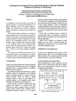
In Figure 1, a classification of quality assessment meth-
ods for video object-based segmentation is shown. Reference
methods require ground-truth information as opposed to
no-reference methods, which have no such requirement. No-
reference methods can be further subdivided to interframe,
where the temporal consistency of segmentation from one
frame to another is taken into consideration, and intraframe,
wherethisisnotanissue.
In relation to the assessment of still segmented images,
although there have been a number of noteworthy attempts
such as [3] for grey-level imagery and [4]forcolourimagery,
a commonly accepted approach has not emerged. Other re-
searchers have incorporated elements of human visual per-
ception [5], especially in the field of image compression [6].
Nevertheless such efforts have been moderately successful in
establishing a credible relationship between human visual
perception and an objective measurement of quality.
In the case of moving sequences, much less work has
been reported despite the demand for a standardised objec-
tive evaluation methodology from the broadcasting and en-
tertainment industry [7]. Given the lack of objective and au-
tomatic means for evaluation, the generic assessment stan-
dard is based on subjective evaluation [8, 9], which is cum-
bersome, difficult to organise, and requires dedicated infras-
tructure of a very high specification [10].
The straightforward application of metrics developed for
the evaluation of video sequence segmentation has been at-
tempted and proved ineffective [11]. Such metrics are in fact
well suited to describe similarity or dissimilarity between
homogeneous quantities, while video object segmentation
2 EURASIP Journal on Applied Signal Processing
Subjective
Interframe Intraframe
Reference
No reference
(single-stimulus)
Objective
Evaluation methodologies
Figure 1: Methodologies for quality assessment of video object pro-
duction.
often involves the complex interaction of inhomogeneous
features [1] making the performance evaluation of video ob-
ject segmentation even more difficult than the one of still im-
age segmentation [12].
Most performance evaluation methods suitable for
object-based video segmentation rely on the use of ground
truth [14–16]. In [16, 17], a human visual system (HVS)
driven approach is presented using a perceptually weighted
set of evaluation metr ics. The creation of suitable ground
truth information typically involves the manual segmenta-
tion of moving objects of interest. Unfortunately this requires
a formidable amount of operator effort, concentration, and
experience and ultimately prevents any systematic experi-
mentation beyond just a limited number of frames.
Taking into account the above difficulties, it is evident
that methods that do not rely on ground-truth references
(single stimulus) would be of significant practical value es-
pecially for the purpose of algorithmic performance compar-
isons involving sequences of a longer duration. With some
notableexceptions[13, 18] this class of no-reference assess-
ment methods is rather under-represented in the literature.
In this work, we formulate a single-stimulus, intraframe
assessment method suitable for the evaluation of the perfor-
mance of object-based segmentation algorithms. Some as-
pects of our approach are derived from the single-stimulus
method described in [13]. An important element of our ap-
proach is the consideration of local spatial and temporal
characteristics of an objec t of interest on a frame-by-frame
basis. This diminishes the influence of object inhomogeneity
on the overall result. On the other hand, the colour and mo-
tion boundary criteria used in [13] do not take into account
that objects are coherent spatio-temporal entities.
The novelty of our approach lies additionally in the de-
velopment of a unified method for dealing with both spa-
tial and temporal data in the presence of noisy and uncer-
tain data. This method relies on the concept of normalised
differential convolution (NDC). The criteria for the localisa-
tion of correct spatial and temporal boundaries are enriched
by the introduction of a requirement on the spatio-temporal
consistency of the contrast information. The approach is in-
dependent of parameter definition and experimental results
show an increased robustness to noise a nd increased sensi-
tivity to local error with respect to the methods already pro-
posed [13].
The proposed evaluation method is of great help not just
in the performance evaluation of segmentation, but also in
the correction of erroneous segmentations in all those ar-
eas requiring a high segmentation quality. Referring to the
classification of application scenarios in [19], this method-
ology targets both off-line user-interactive and non-user-
interactive applications and real-time user-interactive appli-
cations. Examples of the first category are all applications
that need to produce semantic information, which may be
reused: broadcasting and video production for database stor-
age. Examples of the second category are videotelephony and
videoconference.
This paper is structured as follows. In Section 2, the con-
ceptual methodology for obtaining local accuracy measures
without the use of ground truth is presented. In Section 3,
the characteristics of the current local methods are described,
improvements to the current methodology are suggested,
and the improved methodology is embedded in a unified
method for dealing w ith spatial and temporal data in pres-
ence of noise and uncertainty. In Section 4, the proposed
method is compared to the previous methodology with the
use of both automatic object segmentation and ground truth,
obtained by manual segmentation, and its application to al-
gorithmic performance comparison is demonstrated. Con-
clusions follow in Section 5.
2. METRICS USING COLOUR AND MOTION
DISPARITIES
The proposed method relies on the computation of metrics
which capture the disparity in terms of colour a nd motion
between a djacent regions in a previously generated segmen-
tation map. In that sense, our work has similarities with [20]
and for the benefit of the reader, we briefly summarise some
of the key notions.
2.1. Colour disparity metric
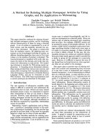
The colour values of pixels just inside and just outside of a
segment boundary are considered. In order to define the just
outside and just inside, normal lines of length L are drawn
from the boundary at equal intervals towards the outside and
the inside of the segment as shown in Figure 2(a), obtain-
ing K sampling points on the boundary. The end points are
marked as p
i
O
and p
i
I
,fori = 1, , K. The colour disparity
metric d
C
(t), of a segment in frame t is defined in (1)and(2)
below:
0 ≤ d
C
(t) =
1
K
K
i=1
d
C
(t, i) ≤ 1, (1)
where
d
C
(t, i) =
C
i
O
(t) − C
i
I
(t)
√
3 × 255
2
(2)
and C
i
O
(t) is the average colour calculated in an M × M
neighbourhood of pixel p
i
O
(x, y, t). C
i
I
(t) is defined similarly.
The colour met ric for the whole sequence is
0
≤ D
C
= f
d
C
(t), t = 1, , T
,(3)
R. Piroddi and T. Vlachos 3
M
M
L
C
i
O
p
i
O
90
◦
C
i
I
p
i
I
Object boundary
Inside objectOutside object
Pixel on the boundary
(a)
A
o
R
A
i
E
Object boundary
Inside objectOutside object
Pixel on the boundary
(b)
Figure 2: (a) Definition of just inside and just outside areas for the computation of contrast in [13] and (b) definition of the support area for
the applicability function in the NC/NDC.
where f (·) denotes a linear function obtained by the con-
tributions of T colour disparities measures d
C
calculated for
frames at instants t
= 1, , T,and·denotes the Euclidean
distance.
2.2. Motion disparity metric
The motion metric d
M
(t)foraframet is conceptually similar
to the colour metric discussed above. Here, v
i
O
(t)andv
i
I
(t)
denote the average motion vectors calculated in an M
× M
neighbourhood of pixels p
i
O
(x, y, t)andp
i
I
(x, y, t). Then,
d(v
i
O
(t), v
i
I
(t)) denotes the distance between the two average
motion vectors and is calculated according to the following:
0
≤ d
v
i
O
(t), v
i
I
(t)
=
v
i
O
(t) − v
i
I
(t)
v
i
O
(t)
+
v
i
I
(t)
. (4)
Whenever possible, it is advisable to associate a reliability
measure to the estimates of the motion vectors. In [20] the
reliability measure is based on the motion and colour coher-
ence in the prediction of the motion between frame t and
t +1.Let usdenote b
i
(t +1) as the backward motion vector at
location p
i
+ v
i
in frame t +1;c(p
i
, t) as the colour intensity;
and parameters σ
m
and σ
c
as the standard deviations of the
motion field and colour in frame t, respectively. The reliabil-
ity measure R(v
i
(t)) for a neighbourhood around pixel i in
frame t is defined as
R
v
i
(t)
=
exp
−
v
i
(t) − b
i
(t +1)
2
2σ
2
m
×
exp
−
c
p
i
, t
−
c
p
i
+ v
i
, t +1
2
2σ
2
c
.
(5)
For each sample i on the boundary of a segmented object,
two motion averages v
i
O
(t)andv
i
I
(t) of a neighbourhood im-
mediately outside and immediately inside the boundary lo-
cation i should be calculated. Therefore, the total reliability
measure w
i
for the location i is a combination of the reliabil-
ity measures of v
i
O
(t)andv
i
I
(t):
0
≤ w
i
= R
v
i
O
(t)
·
R
v
i
I
(t)
≤
1. (6)
The reliability measure may be used as a weight for the dis-
tance measure expressed by d(v
i
O
(t), v
i
I
(t)), defined in (4).
This is necessary to reduce the influence of erroneous esti-
mates in the calculation of the motion disparity metric. The
weighted distance between the two average motion vectors is
then defined as
d
M
(t, i) = d
v
i
O
(t), v
i
I
(t)
·
w
i
. (7)
Finally, the overall motion metric d
M
(t) is obtained as the
sum of the differences in corresponding motion vectors just
inside and just outside the motion boundary (a sort of mo-
tion contrast) weighted by the reliability of the same motion
4 EURASIP Journal on Applied Signal Processing
vectors and normalised by the sum of all the weights, for a
number K of boundary samples of the object in frame t. This
is expressed by
0
≤ d
M
(t) = 1 −
K
i=1
d
M
(t, i)
K
i
=1
w
i
≤ 1. (8)
3. NEIGHBOURHOOD TOPOLOGY
The neighbourhood topology used in [20] is subject to the
following limitations.
(i) Occasional unreliability due to the fact that the av-
erages are calculated in an area further away from
the boundary. In fact the closest pixel is at a distance
L
− (M/2).
(ii) No adaptation to the local structure of the boundary.
The neighbourhood used for the calculation of the
averages does not follow the local curvature of the
boundary, but its shape is fixed.
(iii) The distance from the boundary is not taken into ac-
count. All the pixels in the neighbourhood contribute
in equal measure to the average, irrespective to their
actual distance from the boundary, which can be up to
L +(M/2).
In response to the above we have redesigned the neigh-
bourhood topology so that it follows closely the actual
boundary between two segments and therefore provides an
element of local adaptation.
In Figure 2(b) a schematic description of the proposed
improvement is shown. Metrics are calculated for each point
p
b
belonging to the boundary. The area for the calculation of
the contrast is defined by a circle of radius R centred in p
b
.
This area of support closely follows the object boundary and
allows the collection of information from areas adjacent to
the boundary inside, A
i
, and outside, A
o
, the moving object.
3.1. Treatment of unreliable and missing data
It should be noted that not all boundary elements contribute
to the calculations, but an element of sampling is introduced
in [20]. In this work, we avoid the sampling of the bound-
ary when possible. However, especially when dealing with
motion information, pixels along the boundary may convey
noisy or incorrect information and may need to be excluded
from the computation, introducing some irregular sampling.
Thismayleadtofurtherdifficulties in the determination of
the sampling points: if they are regularly spaced, it is pos-
sible that they ignore salient features of the contour. If they
are irregularly spaced, there is the added complication of de-
termining a suitable sampling criterion and a strateg y needs
to be developed for dealing with locations that do not con-
tribute to the sampling operation, in which case data will
be missing altogether. Additionally, if colour/intensity infor-
mation inside the data collection neig hbourhood is relatively
homogeneous, the corresponding motion estimates are likely
to be unreliable.
We reduce the influence of unreliable and missing data
due to irregular sampling by employing the normalized dif-
ferential convolution (NDC).
3.2. Normalized differential convolution
In [21], the problem of image analysis with irregularly sam-
pled and uncertain data is addressed in a novel way. This in-
volves the separation of both data and operator applied to
the data in a signal part and a certainty part. Missing data in
irregularly sampled fields are handled by setting the certainty
of the data equal to zero.
In our work we consider the normalized differential con-
volution which is a variant of the above methodology [21–
23]. In addition to the separa tion of the data into a signal
part, which will be indicated as f (x, y), and a cer tainty part,
indicated as c(x, y), the NDC requires the use of an appli-
cability function g(x, y) and its derivatives. The applicability
function and its derivatives indicate what is the contribution
of the data to the gradient according to their relative posi-
tion. Additionally, they determine the extent of the influence
of the neighbourhood to the measure.
Let us denote with C the convolution of image f (x, y),
previously weighted by a reliability or certainty map c(x, y),
with a smoothing filter g(x, y):
C(x, y)
≡
f (x, y)c(x, y)
∗ g(x, y). (9)
Let us f urther denote with NC the convolution of the cer-
tainty map c(x, y) with the filter g(x, y):
NC(x, y)
≡ c(x, y) ∗ g(x, y). (10)
Then the point-by-point division between the outputs of
the two convolutions a bove is the normalized convolution.
Among other applications, this has been used for image de-
noising and image reconstruction purposes when pixel val-
ues are occasionally unreliable or even totally unavailable
within a given neighbourhood.
Dropping the explicit dependence of C and NC on (x, y),
we now define the following:
C
x
≡ (xg) ∗ cf,
NC
x
≡ (xg) ∗ c,
C
y
≡ (yg) ∗ cf,
NC
y
≡ (yg) ∗ c,
(11)
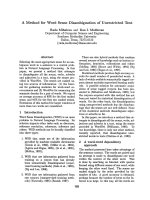
where xg and yg indicate the multiplication of filter g with
variables x and y.Asfilterg is a smoothing filter, fil-
ters xg and yg are edge enhancement filters. For the fil-
ter used in [22], xg
= x cos
2
(π
x
2
+ y
2
/8) and yg =
y cos
2
(π
x
2
+ y
2
/8) and those are shown in Figure 3.
We also define [24]vectorD
Δ
(x, y) ≡ [D
x
, D
y
], the com-
ponents of which, D
x
and D
y
, are calculated as follows:
D
x
≡ NC ×C
x
− NC
x
×C,
D
y
≡ NC ×C
y
− NC
y
×C.
(12)
R. Piroddi and T. Vlachos 5
10
5
0
−5
−10
y
−10
−5
0
5
10
x
−1
−0.5
0
0.5
1
g(x, y)
(a)
10
5
0
−5
−10
y
−10
−5
0
5
10
x
−1
−0.5
0
0.5
1
g(x, y)
(b)
10
5
0
−5
−10
y
−10
−5
0
5
10
x
−1
−0.5
0
0.5
1
g(x, y)
(c)
10
5
0
−5
−10
y
−10
−5
0
5
10
x
−1
−0.5
0
0.5
1
g(x, y)
(d)
10
5
0
−5
−10
y
−10
−5
0
5
10
x
−1
−0.5
0
0.5
1
g(x, y)
(e)
10
5
0
−5
−10
y
−10
−5
0
5
10
x
−1
−0.5
0
0.5
1
g(x, y)
(f)
Figure 3: The product of filter g(x, y) with variables x and y and some functions of them may produce some highpass filters shown here.
These filters were normalised so that their maxima are equal to one, for visualisation purposes only. (a) g(x, y). (b) xg(x, y). (c) yg(x, y). (d)
xyg(x, y). (e) x
2
g(x, y). (f) y
2
g(x, y).
Next we define the 2 × 2matrixN
Δ
, as follows:
N
Δ
≡
N
xx
N
xy
N
yx
N
yy
, (13)
where
N
xx
≡ NC ×
x
2
g
∗
c
−
NC
2
x
,
N
xy
≡ N
yx
= NC ×
(xyg) ∗c
− NC
x
×NC
y
,
N
yy
≡ NC ×
y
2
g
∗ c
− NC
2
y
.
(14)
If filter g
= cos
2
(π
x
2
+ y
2
/8), then filters x
2
g, y
2
g,and
xyg are given by x
2
g = x
2
cos
2
(π
x
2
+ y
2
/8), y
2
g =
y
2
cos
2
(π
x
2
+ y
2
/8), and xyg = xycos
2
(π
x
2
+ y
2
/8), and
those are shown in Figure 3. The elements of matrix N
Δ
de-
pend only on the certainty of the data. N
xx
gives an estimate
of the certainty of the data along the x direction, N
yy
gives
an estimate of the certainty of the data along the y direction,
and N
xy
gives an estimate of the certainty of the data along
both the x and y directions.
6 EURASIP Journal on Applied Signal Processing
The normalized differential convolution (NDC) U
NΔ
is
finally defined as
U
NΔ
≡ N
−1
Δ
D
Δ
, (15)
where N
−1
Δ
is the inverse of the 2 × 2matrixN
Δ
.
The effectiveness of the method towards dealing with ir-
regularly sampled and incomplete data was demonstrated in
[24, 25] for one-dimensional and two-dimensional signals,
respectively. For a typical natural imagery, even if only 10%
of the original pixels are known, the image gradient can be
recovered to a satisfactory extent. It has also been shown, that
the NC yields the best reconstruction results for reconstruc-
tion of irregularly sampled data for sampling ratios smaller
than 5%. Additionally, NDC is the only method that allows
the direct calculation of gradients of irregularly and sparsely
sampled data [24].
3.3. Adaptation to local topology
As shown in Figure 3, the applicability function used in [21]
and its derivatives are symmetrical and fixed in size. How-
ever, it was shown [26] that an element of adaptation to
the local topology can yield performance g ains relative to
the performance obtained using a nonadaptive filter function
[21].
For our purposes, it would be advantageous to use a
smoothing function which can have variable size and orien-
tation so that it can adapt to the local curvature of the seg-
ment boundary. This can be achieved by using a Gaussian
type of function whose variance can be adjusted to provide
the desired adaptation. Since our topology is inherently two-
dimensional, we use a two-dimensional Gaussian function
with parameters σ
u
in the horizontal direction and σ
v
in the
vertical direction.
The local curvature is estimated using the regularized gra-
dient structure tensor T [27]definedas
¯
T
=
¯
∇I∇I
T
= λ
u
u
u
T
+ λ
v
v
v
T
, (16)
where I is the intensity of the grey-level image,
u is the eigen-
vector of the largest eigenvalue λ
u
, which determines the lo-
cal orientation, the over-lining indicates the averaging of the
elements over a local neighbourhood, and the superscript T
indicates the transpose of the vector. Defining as A the lo-
cal anisotropy, A
= (λ
u
− λ
v
)/(λ
u
+ λ
v
), the scales are finally
calculated as
σ
u
= (1 + A)σ
a
, σ
v
= (1 − A)σ
a
. (17)
Using the above, the applicability function reflects the
curvature of the boundary so that, for example, elonga-
tion can be induced in the direction of the normal to that
boundary, as shown by the elliptical area of support E in
Figure 2(b). At the same time, this provides a mechanism
for a reliability weighting of pixels according to their distance
from the boundary.
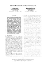
3.4. Computation of metrics using the NDC
The NDC provides a way of obtaining dense contrast infor-
mation on a multiplicity of different features, using sparse
and/or irregular and uncertain estimates of such features.
The flowchart in Figure 4 explains the method of compu-
tation of the dispar ity metrics with the use of the NDC. In
this figure, the boundaries of the object, the segmentation of
which is evaluated, are denoted collectively by b.However,
b is the union of all points p
b
belonging to the boundary of
the object. Colour description of any frame is given by three
colour channels c
1
= R, c
2
= G,andc
3
= B. In general, any
three-dimensional colour space other than Red-Green-Blue
may be employed. The motion description is g iven by the
optic flow, which consists of two components, the horizontal
u and the vertical v component.
To summarise, the NDC is a function of a feature f cal-
culated on a location p, in our case of a t wo-dimensional reg-
ular grid, that is, NDC
≡ NDC( f , p). In the application here
considered, the NDC is calculated on the location of an ob-
ject boundary, indicated as p
b
. The features considered are
colour c, which consists of three colour planes c
1
, c
2
,andc
3
,
and motion m, which consists of the horizontal and vertical
estimates of the optic flow, indicated as u and v,respectively.
The colour and motion metrics, CM and MM, respectively,
are therefore calculated as
CM
p
b
=
NDC
c, p
b
=
NDC
c
1
, p
b
+NDC
c
2
, p
b
+NDC
c
3
, p
b
3
,
MM
p
b
=
NDC
m, p
b
=
NDC
u, p
b
+NDC
v, p
b
2
.
(18)
The applicability function is adapted to the shape and the lo-
cal orientation of the boundary. It provides weighting with
regards to the distance from the boundary on the location
p
b
. It also provides averaging of the information on a kernel
centred in p
b
, which gives robustness to noise.
The certainty function provides extra robustness to noise
as noisy data can be discarded or weighted negatively. There-
fore the information is reconstructed on the basis of more
certain data. Additionally, in a novel element of modelling,
a part of the certainty function is used to provide an indica-
tion of the spatio-temporal coherence of the boundary of the
objects.
This requires further explanation. In the motion metric,
one may use the certainty function to model both the spatio-
temporal coherence and the uncertainty of the motion esti-
mates. In this method, the certainty function c(x, y)iscom-
posed of three elements.
The first element is motion certainty, mc,afunction
reflecting motion estimation reliability. In our approach, a
robust motion estimator has been employed [28]. Robust
methods exclude, in the estimate of the motion, the points
that do not comply with the model used for the estimation,
that is, the outliers. We use outlier information coded into a
binary map mc, which makes the distinction between a point
being an outlier or not. Outliers are then ignored in the cal-
culation of the NDC.
Additionally, motion estimation is more reliable in tex-
tured areas and vice versa. Thus a measure of texture activity
has been incorporated as the second element of our certainty
R. Piroddi and T. Vlachos 7
Average of 3 NDC Average of 2 NDC
Colour disparity metric Motion disparity metric
++
Find value of NCD on
object boundaries
Find value of NDC on
object boundaries
NDC
(R, b)
NDC
(G, b)
NDC
(B,b)
NDC
(u, b)
NDC
(v,b)
Calculate NDC of
colour channels
Calculate NDC of
optic flow
NDC
of R
NDC
of G
NDC
of B
NDC
of u
NDC
of v
c
Certainty
×
RG B buv mctccc b
Object
boundaries
Colour channels Optic-flow components Reliability masks
Object
boundaries
Colour disparity metric Motion disparity metric
Figure 4: Flowchart of proposed method of calculation of disparity metrics with the use of NDC.
map, indicated as tc. The texture activity is expressed tak-
ing into consideration the following fact. The more distant a
point is from an edge, the more difficult it becomes for the
motion estimator to find a good match. We therefore calcu-
lateanedgemapofagivenframeandassociatetoeachpixel
the Euclidean distance between its own location and the clos-
estedgetoit[29]. This mat rix, scaled in the range from 0–1,
provides what the required texture certainty measure tc.
Even in highly textured areas, errors are concentrated
in the vicinity of motion boundaries, due to so-called
smoothness constraints frequently used in motion estimation
methodologies. To account for that, a measure of error along
motion boundaries can be obtained by assuming that the
motion boundary of an object coincides with spatial bound-
aries. This is a spatio-temporal coherence consideration and
it is reflected by the third element of our certainty, denoted
as cc. In order to calculate the matrix cc, we calculate the mo-
tion boundaries corresponding to the object to be evaluated
using an edge detector on the component of the optic flow.
We then calculate the distance between each motion bound-
ary location and the closest colour edge. The colour edges
have already been used to produce the tc. If the distance at
a location of the boundary is bigger than a given threshold
d
T
, then such a location is set to zero in cc and ignored in
the calculation of the ND C. All the other motion boundary
locations are set to one in cc.
The overall certainty map contains a measure of motion
reliability, a m easure of spatial reliability, and a m easure of
spatio-temporal reliability. The three elements are combined
into a single certainty map c to be used for the calculation of
the NDC:
c(x, y)
= mc(x, y) · tc(x, y) · cc(x, y), (19)
where the operator ·indicates point-by-point multiplication.
The coherence map cc may be used also to enforce spatio-
temporal coherence in the calculation of the colour metric
CM.
4. EXPERIMENTAL WORK
The results shown in this section were obtained using six
standard MPEG test sequences called Renata, Mobile and
Calendar, Garden, Mother and Daughter, Foreman,andSte-
fan [30]. To avoid complications due to interlacing, only
even-parity field data were retained.
Renata is a head-and-shoulders sequence, showing a per-
son moving in front of a complex-textured background. The
background consists of synthetic textures both in luminance
and colour. The sequence presents very low-contrast and
very similarly textured areas between backg round and fore-
ground in some frames. A field from test sequence Renata is
shown in Figure 5(a), showing the boundaries of the moving
8 EURASIP Journal on Applied Signal Processing
(a) (b)
(c) (d)
(e) (f)
Figure 5: (a), (c), (e) Boundaries of manual segmentation of moving object superimposed to the original field and (b), (d), (f) boundaries
of erroneous segmentation of the same moving object for test sequences Renata, Mobile and Calendar, and Garden, respectively.
object, manually segmented. In Figure 5(b), an incorrectly
segmented video object corresponding to the foreground ob-
ject is shown.
Mobile and Calendar is a synthetic sequence rich in
colour and textures. It presents three main moving objects. In
this work, we present only data from the calendar object. The
calendar is moving behind the train and in the upper part
of the fr ame, following a roughly vertical direction. There is
slight camera panning. A field from test sequence Mobile and
Calendar is shown in Figure 5(c), showing the boundaries
of the moving object, manually segmented. In Figure 5(d),
an incorrectly segmented video object corresponding to the
foreground object is shown.
Garden (flower garden) is a natural image rich in tex-
ture. St rictly speaking, there is no major object in motion,
the movement is apparent, and it depends on the panning
of the camera and scene depth. A tree appears to move from
the right to the left at a higher speed than the objects fur-
ther away from the observer. This sequence does not have
a high contrast and has very similar textures in parts of the
tree trunk and parts of the wooden fences of the surround-
ing g ardens. A field from test sequence Garden is shown
in Figure 5(e), showing the boundaries of the moving ob-
ject, manually segmented. In Figure 5(f), an incorrectly seg-
mented video object corresponding to the foreground object
is shown.
R. Piroddi and T. Vlachos 9
0.2
1
2
3
4
5
6
7
8
9
10
(a)
0.2
1
2
3
4
5
6
7
8
9
10
(b)
0.4
2
4
6
8
10
12
14
16
18
20
(c)
0.4
5
10
15
(d)
0.4
5
10
15
20
25
30
(e)
0.2
5
10
15
(f)
Figure 6: Map of intensity of colour contrast along (a), (c), and (e) the boundary of the manually segmented object and (b), (d), and (f) the
boundaries of the erroneous object segmentation. The colour bars indicate the magnitude of the contrast in each figure.
Mother and Daughter is a head-and-shoulders sequence.
It presents a woman and a young girl talking and moving
their heads and hands in front of a simple static background.
The colour contrast between background and foreground is
low.
Foreman is a head-and-shoulders sequence of a con-
struction worker set against a complex background with low
colour contrast.
Stefan is a dynamic sport sequence showing a tennis
player against a richly textured background of spectators. As
expected, the movement contained in the sequence is very
complex.
Manually extracted ground truths and erroneous seg-
mentations have been used in the experiments described be-
low. Examples of ground truths and erroneous segmenta-
tions are shown in Figure 5.
4.1. Colour disparity metric
The colour disparity metric, CM, is calculated as the value
of the NDC computed on the three colour components on
the original field, on the position of the boundary taken into
account.
We have applied the metric CM to the boundary of both
ground truths and erroneous segmentation of video objects
moving in the test sequences. The results of such contrast
measurement are shown in Figures 6(a), 6(c),and6(e) for
the ground truths and in Figures 6(b), 6(d),and6(f) for
the erroneous segmentations of test sequences Renata, Mo-
bile and Calendar, and Garden. Erroneous parts of the object
boundary are consistently signalled for all test sequences by
the lowest value of CM. The corresponding values of CM cal-
culated in the corresponding ground truths are much higher.
10 EURASIP Journal on Applied Signal Processing
Renata
(a)
(b)
Mobile and Calender
(c)
(d)
Garden
(e)
(f)
Figure 7: (a) Nontextured and (b) textured boundary definition in Renata, Mobile and Calendar, and Garden, respectively.
The most important characteristic of the approach pro-
posed in this paper is the higher sensitivity to a shift in the
position of the boundary. Additionally, it is important to ver-
ify the influence of noise on the measure, since the proposed
method is based on gradient estimation, which tends to be
more sensitive to noise, while the approach in [13], which
produces the colour disparity metric, d
C
(indicated in the di-
agrams with the legend Erdem, Tekalp and Sankur, given the
names of the authors of such metric), is based on an average
of colour planes.
In order to validate the sensitivity of the method to an
incorrect placement of the boundary, the value of CM is cal-
culated for a range of shifts of the motion boundary in the di-
rection of the normal to the boundary at a particular location
p
b
and compared to d
C
, calculated on the same boundary
points. The boundary is defined by the pixels of the bound-
ary of the manually segmented object. The two contrast mea-
sures are normalised with reference to their maximum value,
in order to compare them. The sensitivity of the measure is
directly proportional to the magnitude of its g radient.
R. Piroddi and T. Vlachos 11
The additional element that needs to be validated is the
sensitivity to noise in the image. In order to do so, the bound-
aries have been divided into two categories: boundaries that
lie on a nontextured support, with examples of them shown
in Figures 7(a), 7(c),and7(e) and boundaries that lie on a
textured support, with examples of them shown in Figures
7(b), 7(d),and7(f). The classification into textured and non-
textured boundaries is based on [34]. The boundaries that lie
on a textured support are expected to suffer from a higher
level of noise in the estimation of the gradient.
For the calculation of the contrast measure in [13], a dis-
tance L
= 20 from the boundary and a half range M = 10
of the area of calculation of the averages have been used. In
order to establish an element of correspondence between the
two measures: CM in our work and d
C
,in[13], we used an
applicability function elongated in the direction of the nor-
mal to the boundar y for the major axis of an ellipse of h alf
length of R
= 30. Therefore the size of the filter used here
is 61
× 61 pixels, in order to be comparable to the reference
method. In general, the size of the filter depends on the data.
The larger the area of missing or uncertain information, the
larger the filter. This is because the filter needs to be at least
one pixel wider than the largest dimension of the area to be
estimated. The speed of the proposed algorithms depends on
the size of the filter as well as the resolution of the images.
For images of common intermediate format (CIF) resolu-
tion 352
× 288 pixels and a filter of size 21 × 21 pixels, it
takes 16 seconds to calculate the disparity metric for each
colour channel of the resolution of the frame, with the use
of a Matlab-interpreted script on a 433 MHz Intel Celeron
CPU. The same considerations apply to the motion disparity
metric, in term of filter size and time required for processing
a single component of the optic flow.
The contrast metric sensitivity is proportional to the
value of the derivative of the disparity metrics, therefore the
steeper the descent of the curve representing the metric, the
higher the sensitivity. In Figure 8, the comparison of the dis-
tortion metrics obtained for all six test sequences are show n,
in the case where the object boundary does not lie on a tex-
tured support. In Figure 9, the comparison of the distortion
metrics obtained for all six test sequences are shown, in the
case where the object boundary lies on a textured support.
The results obtained using CM are always more sensitive to
the presence of the boundary than the ones obtained with the
use of d
C
. The contrast value is oscillating more for CM than
d
C
in the case of textured boundaries, especially in the cases
of Mobile and Calendar and Garden, which contain more
texture. However, in the textured regions, the detection of
the boundary is clear with CM, while d
C
does not differenti-
ate the presence of the object boundary, being almost flat for
all values of shift examined.
4.2. Motion disparity metric
In Figure 10, the horizontal and vertical components of
the optic flow are shown, with the super-imposition of the
boundaries of the manually segmented object in case of
test sequence Renata. The two components are used in the
calculation of the motion disparity metrics. The motion es-
timation used here is obtained by a robust motion estimator
[28]. This way it is also possible to have a map of motion
outliers, shown in Figure 12(a).
In case of the motion measure presented in [13], indi-
cated as d
M
, the contrast is weighted by the reliability of the
motion vectors. In order to implement the reliability mea-
sures, the parameters σ
m
and σ
c
have been chosen in accor-
dance with the standard deviation of the motion vector and
colour planes, respectively. The two components of the reli-
ability measure are shown in Figures 11(a) and 11(b), while
their combined effect is shown in Figure 11(c). The weight-
ing scheme proposed here has some disadvantages. In case a
motion estimation error occurs in a nontextured area (which
is an area where errors in the motion boundary commonly
occur), the reliability functions taken into account here do
not have any support in order to identify the problem. In Fig-
ures 11(a) and 11(b), the errors are shown around the mo-
tion boundaries.
In the proposed method, it is possible to distinguish
between the sig nals, that is, the motion estimates, and their
certainty, which will be used for normalisation of the mea-
sure. A robust motion estimator produces a map of the re-
liability of the estimates, shown in Figure 12(a), where the
outliers are shown as zeros. This is exactly an example of a
certainty map that can be directly used for the purpose of cal-
culating the NDC. The motion outliers will be effectively ig-
nored from the calculation. The information needed at their
location is supplied by the local information in a neig h bour-
hood along the normal to the boundary. Moreover, as it is
a well-known fact that motion estimators perform poorly in
nontextured areas, an additional component of the certainty
map is given by the distance of a pixel from textured areas,
as shown in Figure 12(b). The rationale for this component
of the certainty map is that most motion estimators rely on a
neighbourhood search to find a suitable match. With increas-
ing distance from an edge or a textured area, the likelihood
of finding a useful reference for motion estimation decreases.
We model this dependence directly: the range of the certainty
measure goes from 1 to a minimum, c
min
= 1 − d
max
.Here,
d
max
corresponds to the maximum distance from any tex-
tured area. The distance d from the textured areas is scaled
in such a way so as to obtain a range of certainty between 1,
where an area is textured, and c
min
, as shown in Figure 12.
The third reliability component, shown in Figure 12(c),isa
map of the motion boundaries that do not have any corre-
spondence to spatial boundaries, at a distance d
T
= 3. This is
used as an element of spatio-temporal coherence. The three
reliability maps are then multiplied together to give the final
certainty map.
With the proposed method, the motion measure MM is
calculated as the average NDC estimated from the horizon-
tal and vertical components of the optic flow, u and v,at
each point of the boundary p
b
.InFigure 12(d), the NC of
the horizontal flow component, u, obtained using the pro-
posed certainty map is shown. The boundaries of the man-
ually segmented moving object have been superimposed to
give an idea of the shape of the object. The calculation of
12 EURASIP Journal on Applied Signal Processing
0 5 10 15 20 25 30
Shift (
±pixels)
0
0.1
0.2
0.3
0.4
0.5
0.6
0.7
0.8
0.9
1
Colour disparity metric
Erdem, Tekalp, and Sankur
Proposed method
(a)
0 5 10 15 20 25 30
Shift (
±pixels)
0
0.1
0.2
0.3
0.4
0.5
0.6
0.7
0.8
0.9
1
Colour disparity metric
Erdem, Tekalp, and Sankur
Proposed method
(b)
0 5 10 15 20 25 30
Shift (
±pixels)
0.1
0.2
0.3
0.4
0.5
0.6
0.7
0.8
0.9
1
Colour disparity metric
Erdem, Tekalp, and Sankur
Proposed method
(c)
0 5 10 15 20 25 30
Shift (
±pixels)
0
0.1
0.2
0.3
0.4
0.5
0.6
0.7
0.8
0.9
1
Colour disparity metric
Erdem, Tekalp, and Sankur
Proposed method
(d)
0 5 10 15 20 25 30
Shift (
±pixels)
0
0.1
0.2
0.3
0.4
0.5
0.6
0.7
0.8
0.9
1
Colour disparity metric
Erdem, Tekalp, and Sankur
Proposed method
(e)
0 5 10 15 20 25 30
Shift (
±pixels)
0
0.1
0.2
0.3
0.4
0.5
0.6
0.7
0.8
0.9
1
Colour disparity metric
Erdem, Tekalp, and Sankur
Proposed method
(f)
Figure 8: Colour disparity metric for nontextured support in 6 MPEG standard test sequences. The sensitivity of the measure is given by the
gradient of the metric. The proposed method is shown by the dashed curve. (a) Renata, (b) Mother and Daughter, (c) Mobile and Calendar,
(d) Foreman, (e) Garden, and (f) Stefan.
R. Piroddi and T. Vlachos 13
0 5 10 15 20 25 30
Shift (
±pixels)
0
0.1
0.2
0.3
0.4
0.5
0.6
0.7
0.8
0.9
1
Colour disparity metric
Erdem, Tekalp, and Sankur
Proposed method
(a)
0 5 10 15 20 25 30
Shift (
±pixels)
0
0.1
0.2
0.3
0.4
0.5
0.6
0.7
0.8
0.9
1
Colour disparity metric
Erdem, Tekalp, and Sankur
Proposed method
(b)
0 5 10 15 20 25 30
Shift (
±pixels)
0.1
0.2
0.3
0.4
0.5
0.6
0.7
0.8
0.9
1
Colour disparity metric
Erdem, Tekalp, and Sankur
Proposed method
(c)
0 5 10 15 20 25 30
Shift (
±pixels)
0
0.1
0.2
0.3
0.4
0.5
0.6
0.7
0.8
0.9
1
Colour disparity metric
Erdem, Tekalp, and Sankur
Proposed method
(d)
0 5 10 15 20 25 30
Shift (
±pixels)
0
0.1
0.2
0.3
0.4
0.5
0.6
0.7
0.8
0.9
1
Colour disparity metric
Erdem, Tekalp, and Sankur
Proposed method
(e)
0 5 10 15 20 25 30
Shift (
±pixels)
0
0.1
0.2
0.3
0.4
0.5
0.6
0.7
0.8
0.9
1
Colour disparity metric
Erdem, Tekalp, and Sankur
Proposed method
(f)
Figure 9: Colour disparity metric for textured support in 6 MPEG standard test sequences. The sensitivity of the measure is given by the
gradient of the metric. Our proposed method is shown by the dashed curve. (a) Renata, (b) Mother and Daughter, (c) Mobile and Calendar,
(d) Foreman, (e) Garden, and (f) Stefan.
14 EURASIP Journal on Applied Signal Processing
(a) (b)
Figure 10: Boundaries of the manually segmented object superimposed to (a) the horizontal component of the optic flow and (b) the
vertical component of the optic flow.
(a)
(b)
(c)
Figure 11: (a), (b) are the two components of the motion reliability measure according to [13], the darker areas are the less reliable areas. In
(c), the two elements are combined together, in this case the lighter areas are the more reliable areas.
R. Piroddi and T. Vlachos 15
(a) (b)
(c) (d)
Figure 12: (a) Map of motion outliers. (b) Map of distance from textured support, scaled from 1 (on the textured area) to 0 (maximum
distance from any textured area for the given field). (c) Map of location of moving object that does not correspond to any colour boundary
in the or iginal image. The multiplication of (a), (b), and (c) provides the certainty map for the proposed method, while (d) shows the NC
obtained with the use of the certainty maps proposed in this method, with superimposed boundaries of the hand-segmented object.
the NC is the first step towards the calculation of the NDC
and it gives a clear indication of the transformation that the
optic-flow is subjected to as the result of the use of a given
certainty map. Comparing this figure with Figure 10(a), the
improved correspondence of the optic flow field to the shape
of the object along its boundaries is noticeable. Also, the in-
formation on inner non-textured regions of the object is lost,
because the certainty value associated with these regions in
the map of Figure 12(b) is equal or very close to zero. How-
ever, this is deliberate because the information at the inner
regions of the objects is not relevant for the calculation of
MM. In case a specific application would need the infor-
mation at inner regions, two things could be done: (1) set-
ting the certainty to a value bigger than zero in those ar-
eas or (2) using a larger kernel for the applicability func-
tion.
In Figure 13, the sensitivity of the motion measure MM
is compared to d
M
. Both measures are calculated along the
boundaries of the manually segmented object for the three
test sequences. The plotted values are a function of the shift
from the correct boundary location, along the normal to the
boundary, averaged along all boundary points. The curve ob-
tained using MM is sharper and the maximum has value
equal to 1. This means that the measure is much more sen-
sitive and at the same time more accurate towards locating
the boundary. The d
M
measure never reaches the maximum
value of 1, even when the exact boundary, as identified by a
human observer, is obtained. Additionally, the plateau shows
a lack of sensitivity for the extent of L while there is evidence
of sensitivity to noise.
Finally, in Figure 14, the value of the motion measure
MM calculated for each point along the boundary of the in-
correctly segmented moving objects, for each of the three test
sequences, is shown. As in the case of the colour metric CM,
the lower values of MM consistently identify for all sequences
the presence of an incorrect motion boundary.
4.3. Comparative evaluation of spatio-temporal
segmentation
In Sections 4.1 and 4.2, we have demonstrated the usefulness
and the enhanced sensitivity characteristics of the proposed
disparity metric for the evaluation of the quality of object
identification on a local basis. This means that the evaluation
of the erroneous s egmentation is based only on the compar-
ison of pixels belonging to one object and one frame. This is
useful when a local correction of a generated object is needed.
We further investigate the capability of the proposed met-
rics to monitor the quality of the segmentation obtained for
agivenobjectineachframeofasequence.Thisisdonebyas-
signing each fr ame a global value of either the colour or mo-
tion disparity metric, calculated as the average value along
each element of the boundary. We used frames 10–50 of test
sequences Mobile and Calendar and Garden.
16 EURASIP Journal on Applied Signal Processing
0 5 10 15 20 25 30
Shift (
±pixels)
0
0.1
0.2
0.3
0.4
0.5
0.6
0.7
0.8
0.9
1
Motion dispar ity metric
Erdem, Tekalp, and Sankur
Proposed method
(a)
0 5 10 15 20 25 30
Shift (
±pixels)
0
0.1
0.2
0.3
0.4
0.5
0.6
0.7
0.8
0.9
1
Motion dispar ity metric
Erdem, Tekalp, and Sankur
Proposed method
(b)
0 5 10 15 20 25 30
Shift (
±pixels)
0
0.1
0.2
0.3
0.4
0.5
0.6
0.7
0.8
0.9
1
Motion dispar ity metric
Erdem, Tekalp, and Sankur
Proposed method
(c)
0 5 10 15 20 25 30
Shift (
±pixels)
0
0.1
0.2
0.3
0.4
0.5
0.6
0.7
0.8
0.9
1
Motion dispar ity metric
Erdem, Tekalp, and Sankur
Proposed method
(d)
0 5 10 15 20 25 30
Shift (
±pixels)
0
0.1
0.2
0.3
0.4
0.5
0.6
0.7
0.8
0.9
1
Motion dispar ity metric
Erdem, Tekalp, and Sankur
Proposed method
(e)
0 5 10 15 20 25 30
Shift (
±pixels)
0
0.1
0.2
0.3
0.4
0.5
0.6
0.7
0.8
0.9
1
Motion dispar ity metric
Erdem, Tekalp, and Sankur
Proposed method
(f)
Figure 13: Motion disparity metrics for (a) Renata, (b) Mother and Daughter, (c) Mobile and Calendar, (d) Foreman, (e) Garden, and (f)
Stefan. The sensitivity of the measure is given by the gradient of the metric. Our proposed method is shown by the dashed curve.
R. Piroddi and T. Vlachos 17
0.1
0.5
1
1.5
2
2.5
3
3.5
4
(a)
0.1
0.5
1
1.5
2
2.5
3
3.5
4
(b)
0.2
1
2
3
4
5
6
7
8
9
10
(c)
Figure 14: Motion disparity metric along the boundaries of the erroneously segmented object for test sequences (a) Renata, (b) Mobile and
Calendar, and (c) Garden. The colour bars indicate the magnitude of the contrast in each figure.
Another important use of the evaluation metrics is to
compare different spatio-temporal segmentation methods.
State-of-the-art spatio-temporal segmentation methods are
based mainly on a region-growing paradigm [1]. Since they
need to combine spatial and temporal information, they
may be classified according to the way this combination is
achieved. P arallel spatio-temporal methods perform spatial
and temporal s egmentations separately and then combine
the regions formed on the basis of a set of rules. Alterna-
tively, hierarchical spatio-temporal methods combine the spa-
tial and temporal information initially using a common sim-
ilarity measure and they derive regions from it in an iterative
fashion. We compare here two methods representative of the
two seg mentation st rategies. The parallel method in [31]is
based on a graph-based region-growing method. The hierar-
chical method in [32] is based on the watershed transform.
Different segmentation methods can be evaluated by
monitoring, on a frame-by-frame basis, the value of colour
and motion metrics for any object in the sequence. Addi-
tionally, it is possible to associate to a segmentation method
(for a given sequence), a single figure-of-merit. This can be
achieved, as suggested in [14], by summing the colour and
motion disparity metrics at each frame and then averaging
them over the length of the sequence. We note here that for
such a measure to reflect both spatial and temporal quality
of the segmentation, the colour and motion features need to
be normalised. In this work, we normalised the features with
respect to dynamic range, but other methods may b e used.
Finally, an important issue of any objective evaluation
method is its relevance to subjec tive quality as perceived by
human observers. We present segmentation results obtained
for each of the two methods and the two test sequences under
18 EURASIP Journal on Applied Signal Processing
Figure 15: Frames 10–50 of test sequence Mobile and Calendar, sampled at regular intervals. The boundaries of the objects generated with
(a) parallel [31] and (b) hierarchical spatio-temporal segmentation methods [32] have been blended into the original frames, for the purpose
of subjective evaluation [33].
consideration following the recommendation of the COST
211 Quat initiative regarding the presentation of the stim-
ulus for subjective evaluation [33]. Here, instead of blend-
ing the original frames to the segmentation masks, we blend
the original frames with the boundaries of the segmentation
masks, to facilitate the subjective inspection of segmentation
quality in Figures 15 and 16.
In Figures 17 and 18, colour and motion disparity met-
rics are plotted frame-by-frame for two objects of the Mobile
and Calendar sequence and for the main moving object in
the Garden sequence. The average of the spatial and tempo-
ral metrics over all the frames is also shown as a dashed-and-
dotted line. This unique value represents the overall evalua-
tion of the methods under consideration. According to this
R. Piroddi and T. Vlachos 19
Figure 16: Frames 10–50 of test sequence Garden, sampled at regular intervals. The boundaries of the objects generated with (a) parallel [31]
and (b) hierarchical spatio-temporal segmentation methods [32] have been blended into the original frames, for the purpose of subjective
evaluation [33].
measure in Figure 18, the difference between the two meth-
ods is significant in the case of the Garden sequence, where
the parallel method perfor ms better. In fact, from a subjec-
tive viewpoint, we notice that the closeness of the segmen-
tation boundaries to perceived object boundaries is better
for the parallel method. Moreover, a frame-by-frame inspec-
tion exposes a fluctuation of the metric according to object
segmentation errors resulting in a number of pixels misclas-
sified outside and/or inside of the object. An example of that
is provided by the outline of the toy train in Mobile and Cal-
endar for the parallel method in Figure 17. Here a number of
pixels are erroneously attached to the object under consid-
eration rendering the plotted metric fairly variable from one
frame to the next.
20 EURASIP Journal on Applied Signal Processing
10 15 20 25 30 35 40 45 50
Frame number
10
15
20
25
30
35
40
Disparity metric
Colour
Motion
Average
(a)
10 15 20 25 30 35 40 45 50
Frame number
10
15
20
25
30
35
40
Disparity metric
Colour
Motion
Average
(b)
10 15 20 25 30 35 40 45 50
Frame number
10
15
20
25
30
35
40
Disparity metric
Colour
Motion
Average
(c)
10 15 20 25 30 35 40 45 50
Frame number
10
15
20
25
30
35
40
Disparity metric
Colour
Motion
Average
(d)
Figure 17: Comparative evaluation of two spatio-temporal segmentation methods using the disparity met rics proposed here, calculated on
two objects of the test sequence Mobile and Calendar (a) Parallel method (object: Calendar), (b) hierarchical method (object: Calendar), (c)
parallel method (object: train), and (d) hierarchical method (object: t rain).
Given the effectiveness of these measures, one might ask
whether it would be possible to use them to drive segmen-
tation algorithms in the first place, rather than just employ
them retroactively for evaluation purposes. For straightfor-
ward spatio-temporal segmentation, we have already noted
that the vast majority of methods are region-based methods.
This is because the main aim is the creation of meaningful
video objects, often in the shape of regions. In the proposed
method, the metrics are calculated on a boundary basis,
therefore edges are targeted r ather than regions. For this rea-
son, one might only consider the proposed evaluation tech-
nique as complementary to segmentation techniques used to
produce the video objects in the first place. For example, we
can envisage the use of our metrics in a two-stage process,
where a video object previously identified using conventional
region-based segmentation, is refined locally with boundary
and neighbourhood information, as discussed in Sections 4.1
and 4.2.
5. CONCLUSIONS
In this paper, we have presented a unified method for single-
stimulus quality assessment of segmented video. According
to this method colour and motion features of a moving se-
quence are taken into consideration and their changes across
segment boundaries are monitored. Features are estimated
using a local neighbourhood which preserves the topological
integrity of segment boundaries. Furthermore the proposed
R. Piroddi and T. Vlachos 21
10 15 20 25 30 35 40 45 50
Frame number
10
15
20
25
30
35
40
Disparity metric
Colour
Motion
Average
(a)
10 15 20 25 30 35 40 45 50
Frame number
10
15
20
25
30
35
40
Disparity metric
Colour
Motion
Average
(b)
Figure 18: Comparative evaluation of two spatio-temporal segmentation methods using the disparity met rics proposed here, calculated on
one object of the test sequence Garden. (a) Parallel method. (b) Hierarchical method.
method addresses the problem of unreliable and/or unavail-
able feature estimates by applying the normalized differen-
tial convolution (NDC). Our experimental results have sug-
gested that the proposed method outperforms competing
methods in terms of sensitivity as well as noise immunity for
a variety of standard test sequences.
REFERENCES
[1] P. Salembier and F. Marques, “Region-based representations of
image and video: segmentation tools for multimedia services,”
IEEE Trans. Circuits Syst. Video Technol., vol. 9, no. 8, pp. 1147–
1169, 1999.
[2] D. Zhang and G. Lu, “Segmentation of moving objects in im-
age sequence: a review,” Circuits Systems and Signal Processing,
vol. 20, no. 2, pp. 143–183, 2001.
[3] Y. J. Zhang, “A survey on evaluation methods for image seg-
mentation,” Pattern Recognition, vol. 29, no. 8, pp. 1335–1346,
1996.
[4] M. B orsotti, P. Campadelli, and R. Schettini, “Quantita-
tive evaluation of color image segmentation results,” Pattern
Recognition Letters, vol. 19, no. 8, pp. 741–747, 1998.
[5] X. Zhang and B. A. Wandell, “Color image fidelity metrics
evaluated using image distortion maps,” Signal Processing,
vol. 70, no. 3, pp. 201–214, 1998.
[6] A. M. van Dijk and J B. Martens, “Subjective quality assess-
ment of compressed images,” Signal Processing, vol. 58, no. 3,
pp. 235–252, 1997.
[7] L.M.J.Meesters,W.A.IJsselsteijn,andP.J.H.Seuntiens,“A
survey of perceptual quality issues in three-dimensional televi-
sion systems,” in Stereoscopic Displays and Virtual Reality Sys-
tems X, vol. 5006 of Proceedings of SPIE, pp. 313–326, Santa
Clara, Calif, USA, January 2003.
[8] International Telecommunication Union ITU.R BT.500-11:
Methodology for the subjective assessment of the quality of tele-
vision pictures, 2002.
[9] International Telecommunication Union. ITU.R BT.710-4:
Subjective assessment methods for image quality in high-
definition television, 1998.
[10] M. H. Pinson and S. Wolf, “Comparing subjective video qual-
ity testing methodologies,” in Visual Communications and Im-
age Processing (VCIP ’03), vol. 5150 of Proceedings of SPIE,pp.
573–582, Lugano, Switzerland, July 2003.
[11] L. M. J. Meesters, W. A. IJsselsteijn, and P. J. H. Seuntiens, “A
survey of perceptual evaluations and requirements of three-
dimensional TV,” IEEE Trans. Circuits Syst. Video Technol.,
vol. 14, no. 3, pp. 381–391, 2004.
[12] A. Cavallaro and T. Ebrahimi, “Object-based video: extraction
tools, evaluation metrics, and applications,” in Visual Commu-
nications and Image Processing ( VCIP ’03), vol. 5150 of Pro-
ceedings of SPIE, pp. 1–8, Lugano, Switzerland, July 2003.
[13] C. E. Erdem, B. Sankur, and A. M. Tekalp, “Performance mea-
sures for video object segmentation and tracking,” IEEE Trans.
Image Processing, vol. 13, no. 7, pp. 937–951, 2004.
[14] C. E. Erdem and B. Sankur, “Performance evaluation metrics
for object-based video segmentation,” in Proc. 11th European
Signal Processing Conference (EUSIPCO ’02), vol. 2, pp. 917–
920, Toulouse, France, September 2002.
[15] P. Correia and F. Pereira, “Objective evaluation of relative seg-
mentation quality,” in Proc. IEEE International Conference on
Image Processing (ICIP ’00), vol. 1, pp. 308–311, Vancouver,
BC, Canada, September 2000.
[16] A. Cavallaro, E. D. Gelasca, and T. Ebrahimi, “Objective eval-
uation of segmentation quality using spatio-temporal con-
text,” in Proc. IEEE International Conference on Image Pro-
cessing (ICIP ’02), vol. 3, pp. 301–304, Rochester, NY, USA,
September 2002.
[17] P. Villegas and X. Marichal, “Perceptually-weighted evalua-
tion criteria for segmentation masks in video sequences,” IEEE
Trans. Image Processing, vol. 13, no. 8, pp. 1092–1103, 2004.
[18] P. L. Correia and F. Pereira, “Objective evaluation of video seg-
mentation quality,” IEEE Trans. Image Processing, vol. 12, no. 2,
pp. 186–200, 2003.
22 EURASIP Journal on Applied Signal Processing
[19] P. L. Correia and F. Pereira, “Classification of video segmen-
tation application scenarios,” IEEE Trans. Circuits Syst. Video
Technol., vol. 14, no. 5, pp. 735–741, 2004.
[20] C. E. Erdem, A. M. Tekalp, and B. Sankur, “Metrics for perfor-
mance evaluation of video object segmentation and tracking
without ground-truth,” in Proc. IEEE International Conference
on Image Processing (ICIP ’01), vol. 2, pp. 69–72, Thessaloniki,
Greece, October 2001.
[21] H. Knutsson and C F. Westin, “Normalized and differential
convolution: methods for interpolation and filtering of incom-
plete and uncertain data,” in Proc. IEEE Conference on Com-
puter Vision and Pattern Recognition (CVPR ’93), pp. 515–523,
New York, NY, USA, June 1993.
[22] C F. Westin, K. Nordberg, and H. Knutsson, “On the equiv-
alence of normalized convolution and normalized differential
convolution,” in Proc. IEEE International Conference on Acous-
tics, Speech and Sig nal Processing (ICASSP ’94), vol. 5, pp. 457–
460, Adelaide, SA, Australia, April 1994.
[23] C F. Westin and H. Knutsson, “Processing incomplete and
uncertain data using subspace methods,” in Proc. 12th IAPR
International Conference on Pattern Recognition, vol. 3, pp.
171–173, Jerusalem, Israel, October 1994.
[24] R. Piroddi and M. Petrou, “Dealing with irregular samples,” in
Advances in Imaging and Electron Physics,P.W.Hawkes,Ed.,
vol. 132, pp. 109–165, Elsevier, Amsterdam, The Netherlands,
2004.
[25] M. Petrou, R. Piroddi, and S. Chandra, “Irregularly Sampled
Scenes,” in Image and Signal Processing for Remote Sensing X,
vol. 5573 of Proceedings of SPIE, pp. 319–333, Maspalomas,
Gran Canaria, Spain, September 2004.
[26] T. Q. Pham and L J. van Vliet, “Normalized averaging using
adaptive applicability functions with applications in image re-
construction from sparsely and randomly sampled data,” in
Proc. 13th Scandinavian Conference on Image Analysis (SCIA
’03), vol. 2749 of Lecture Notes in Computer Science, pp. 485–
492, Halmstad, Sweden, June–July 2003.
[27] B. Rieger and L. J. van Vliet, “Curvature of n-dimensional
space curves in grey-value images,” IEEE Trans. Image Process-
ing, vol. 11, no. 7, pp. 738–745, 2002.
[28] M. J. Black, D. J. Fleet, and Y. Yacoob, “Robustly estimating
changes in image appearance,” Computer Vision and Image
Understanding, vol. 78, no. 1, pp. 8–31, 2000.
[29] R. Piroddi, Multiple-feature object-based segmentation of video
sequences, Centre for Vision, Speech and Signal Processing,
University of Surrey, 2004.
[30] R. Koenen, From MPEG-1 to MPEG-21: creating an interoper-
able multimedia infrastructure, International Organisation for
Standardisation—Organisation Internationale de Normalisa-
tion ISO/IEC JTC1/SC29/WG11 (Coding of Moving Pictures
and audio), 2001.
[31] A. A. Alatan, E Tuncel, and L. Onural, “A rule-based method
for object segmentation in video sequences,” in Proc. IEEE In-
ternational Conference on Image Processing (ICIP ’97), vol. 2,
pp. 522–525, Santa Barbara, Calif, USA, October 1997.
[32] J. G. Choi, S W. Lee, and S D. Kim, “Spatio-temporal video
segmentation using a joint similarity measure,” IEEE Trans.
Circuits Syst. Video Technol., vol. 7, no. 2, pp. 279–286,
1997.
[33]A.A.Alatan,L.Onural,,M.Wollborn,R.Mech,E.Tuncel,
and T. Sikora, “Image sequence analysis for emerging interac-
tive multimedia services-the European COST 211 framework,”
IEEE Trans. Circuits Syst. Video Technol., vol. 8, no. 7, pp. 802–
813, 1998.
[34] R. Piroddi and T. Vlachos, “Multiple-feature segmentation of
moving sequences using a rule-based approach,” in Proc. 13th
British Machine Vision Conference (BMVC ’02), vol. 1, pp. 353–
362, Cardiff , UK, September 2002.
R. Piroddi received a Laurea degree in elec-
tronic engineering from the University of
Cagliari, Italy, in 1999. She was awarded
a Ph.D. degree in electronic engineering
from the University of Surrey, UK, in 2004
for her work on object-based segmenta-
tion of video sequences. From October 2002
to August 2005, she worked on irregularly
sampled signal and image processing as a
Research Fellow at the Centre for Vision,
Speech and Signal Processing, University of Surrey, UK. Since
September 2005, she has been a Research Fellow in the Department
of Electrical and Electronic Engineering, Imperial College London,
UK, working on biologically inspired computer vision algorithms.
Her research interests include image/signal processing, with em-
phasis on applications to medical imaging, geoscience and remote
sensing, object-based v ideo processing and compression, cognitive
vision, biologically-motivated computer vision paradigms and in-
formation representation. She is the author of 10 conference and
journal articles.
T. V l a ch o s received a Dipl Ing degree from
the University of Patras, Greece, in 1985
and the M.S. degree from the University
of Maryland, USA, in 1986 both in electri-
cal engineering. For his work on image and
video coding, he was awarded the Ph.D. de-
gree from Imperial College in 1993. From
1985 to 1987, he held research positions at
the University of Maryland and the Insti-
tute for Systems Research working on digital
communication systems and networks. Between 1988 and 1992, he
was a European Commission Fellow at Imperial College and was
associated with Philips Research Laboratories, UK, working on im-
age analysis, image processing, and video coding for very low bit
rate and broadcasting applications. From 1993 to 1997, he was a
Research Engineer at the BBC R&D D epartment where he led var-
ious projects on bit-rate reduction for digital HDTV and archive
restoration. He joined CVSSP at the University of Surrey in 1997,
where he is now a Senior Lecturer in multimedia signal processing.
He is a Chartered Engineer, and a Member of the Technical Cham-
ber of Greece and the IEE. Current research interests are in the areas
of video compression, motion estimation, and archive restoration.