Báo cáo hóa học: "Seamless Bit-Stream Switching in Multirate-Based Video Streaming Systems" doc
Bạn đang xem bản rút gọn của tài liệu. Xem và tải ngay bản đầy đủ của tài liệu tại đây (812.66 KB, 11 trang )
Hindawi Publishing Corporation
EURASIP Journal on Applied Signal Processing
Volume 2006, Article ID 49084, Pages 1–11
DOI 10.1155/ASP/2006/49084
Seamless Bit-Stream Switching in Multirate-Based Video
Streaming Systems
Wei Zhang and Bing Zeng
Department of Electrical and Electronic Engineering, The Hong Kong University of Science and Technology, Clear Water Bay,
Kowloon, Hong Kong
Received 15 August 2005; Revised 18 December 2005; Accepted 15 March 2006
This paper presents an efficient switching method among non-scalable bit-streams in a multirate-based video streaming system.
This method not only takes advantage of the high coding efficiency of non-scalable coding schemes (compared with scalable ones),
but also allows a high flexibility in streaming services to accommodate the heterogeneity of real-world networks. One unique
feature of our method is that, at every preselected switching point, the reconstructed frame at each rate or two reconstructed
frames at different rates will go through an independent or a joint processing in the wavelet domain, using an SPIHT-type coding
algorithm. Another important step in our method is that we will apply a novel bit allocation strategy over all hierarchical trees
that are generated after the wavelet decomposition so as to achieve a significantly improved coding quality. Compared with other
existing methods, our method can achieve the s e amless switching at each preselected switching point with a better rate-distortion
performance.
Copyright © 2006 Hindawi Publishing Corporation. All rights reserved.
1. INTRODUCTION
Due to the rapid growth and wide coverage of the Internet
in recent years, there is a great increase of demand on vari-
ous video services over the Internet, especially the real-time
video streaming service. In contrast with the download mode
where a video session is downloaded entirely to a user before
it can be played, real-time video streaming enables users to
enjoy the video service right after a very small portion of
the whole video session is received. However, the Internet
is an inherently heterogeneous and dynamic network, that
is, the connecting bandwidth between the server and each
user is varying with time. Under such circumstance of var y-
ing bandwidth, how to maintain a robust quality of service
(QoS) is per haps the most challenging requirement during
each service session. In response to this challenge, two differ-
ent source coding approaches have been developed in recent
years, which are briefly outlined in the following.
1.1. Multirate non-scalable coding scheme
versus scalable coding scheme
One straightforward solution to the challenge mentioned
above is to perform a multiple bit-rate (MBR) representa-
tion, that is, to encode each source video into multiple non-
scalable bit-streams, each at a preselected bit-rate. At each
time-slot during the streaming service, an appropriate bit-
stream is selected according to the available bandwidth and
then transmitted to the user. Clearly, each bit-stream gener-
ated here can be encoded optimally at the chosen bit-rate. On
the other hand, however, it is also clear that we cannot make
the best use of the available bandwidth when it is between
two preselected rates.
In a practical streaming system, such an MBR representa-
tion can usually support a small number of bit-rates only, say,
5–8. However, the reality in the Internet is that the bandwidth
can vary among much more rates. To accommodate such a
big variation, an efficient solution is to do a fully scalable rep-
resentation for each source video, such as the fine granularity
scalable (FGS) coding scheme developed in MPEG-4 [1] (the
layered (scalable) coding scheme developed before MPEG-4
can be treated as a special case of the fully scalable represen-
tation). The idea of FGS is to firstly encode an original source
video into a coarse base-layer that is very thin so as to fit some
small bandwidths. Then, the difference between the original
video and the base-layer video forms the enhancement layer
and is further encoded using a bit-plane coding technique.
Bit-plane coding achieves the desired fine granularity scala-
bility, which offers a fully scalable representation on top of
the base-layer. Nevertheless, because of a small bit-rate used
at the base-layer, the quality of the coded base-layer video
is usually very low. Consequently, the motion compensation
2 EURASIP Journal on Applied Signal Processing
High
Critical bit-rates
Low
Coding
quality
Good
Moderate
Bad
Non-scalable,
optimized at
a single rate
FGS
Rate-distortion
curve, optimized
at all rates
continuously
Multirate
representation
Channel bit-rate
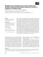
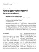
Figure 1: Performance comparison of various video coding schemes.
based on the coded base-layer will generally yield a big resid-
ual signal, which would cost more bits to represent at the en-
hancement layer. Experimental results showed that FGS is of-
ten 3–5 dB worse than the corresponding non-scalable cod-
ing at the same bit-rate [2, 3].
Figure 1 shows conceptually the performances of four
coding schemes: the optimal R-D coding (obtained by op-
timally encoding the source video at every bit-r ate continu-
ously), FGS, non-scalable coding (optimized at a single bit-
rate), and the MBR representation. The goal of designing an
MBR representation is to get as close to the R-D curve as pos-
sible at each preselected bit-rate, while maintaining a con-
stant per formance between two neighboring rates. It can be
seen from Figure 1 that the overall performance of an MBR
representation could be better than that of the FGS scheme.
In practice, the MBR representation has been adopted in
a number of commercial streaming systems such as Windows
Media Services, RealSystem, and QuickTime [4–6]. One very
striking feature of the MBR method is that not only all source
coding tasks but also all channel coding tasks have been com-
pleted before the streaming service. As a result, each stream-
ing service is extremely simple: just get the corresponding
packets based on the available bandwidth (which determines
a bit-r ate) and throw them onto networks. On the other
hand, a scalable video coding (SVC) scheme (including FGS
and the most recent 3D wavelet-based SVC) very likely needs
to handle the channel coding (protection, interleaving, pack-
etization, etc.) in a real-time and on-line fashion, which may
become a bottleneck problem when a large number of users
are served simultaneously.
1.2. Switching among multiple non-scalable
bit-streams
There are many issues in the MBR representation of a source
video, such as how many bit-rates should be used, how to se-
lect these critical rates, how to encode a source video at each
selected rate (jointly with other rates or independently), and
so forth. However, we believe that the most important issue is
that an M BR-based streaming system must be equipped with
a mechanism that allows effective switching between differ-
ent bit-streams when a bandwidth change is detected. In this
scenario, let us use F(t) to denote the frame of a video se-
quence at frame number t,andF
i
(t) to represent the cor-
responding reconstructed frame at rate r
i
(i = 1, 2, , M).
All bits generated after the coding of F(t) at bit-rate r
i
are
grouped into a set Z
i
(t), and C
i
(t) is used to count how
many bits are included in this set. Clearly, C
i
(t) of an in-
tra ( I) frame will be much larger than that of a predic-
tive (P) frame because of the motion compensation used in
all P-frames. Suppose that a bandwidth change is detected
at frame number t
0
(corresponding to a P-frame) and a
switching from F
i
(·)toF
j
(·) is needed rig ht at t
0
. The sim-
plest and most straightforward way is to perform the so-
called direct switching with the transmitted bit sets being
{ , Z
i
(t
0
− 1), Z
j
(t
0
), Z
j
(t
0
+1), }. However, since there
exists mismatching between F
i
(t
0
− 1) and F
j
(t
0
− 1), errors
will occur when F
i
(t
0
− 1) (instead of F
j
(t
0
− 1)) is used to
perform the motion compensation for F
j
(t
0
). More seriously,
such errors will propagate into all subsequent frames until
the next I-frame is received—causing the drifting errors that
are often too large to be accepted, especially in the low quality
to high quality switching case.
In order to achieve seamless (i.e., no drifting errors)
switching, some non-predictive frames can be inserted pe-
riodically into each non-scalable bit-stream as key frames,
and switching is performed by correctly selecting the non-
scalable bit-stream according to the available channel band-
width and delivering the corresponding key frame to the
client [4–6]. To achie ve more flexible bandwidth adaptation,
more key frame insertion points are needed. However, fre-
quently inserting key frames into a non-scalable bit-stream
will seriously degrade the coding efficiency because no tem-
poral correlation is exploited in the coding of a key frame.
Another way to achieve the seamless switching is to trans-
mit the difference between F
i
(·)andF
j
(·) at each switching
point. Although the temporal redundancy has been exploited
in the individual coding of F
i
(·)orF
j
(·), lossless representa-
tion of the difference between them needs a lot of bits (as
overhead)—the number could be much more than that of
anI-frame,whichistoolargetobeaccepted.Asacompro-
mise, further compression is needed to reduce the number
W. Zhang and B. Zeng 3
of overhead bits, while the negative impact is that both F
i
(·)
and F
j
(·) will be changed at each switching point, thus pos-
sibly leading to some qualit y drop. Furthermore, the coding
quality of all subsequent frames before the next I-frame is
very likely to drop also.
So far, there have been a few works on how to mod-
ify F
i
(·)andF
j
(·) so as to achieve the best tradeoff be-
tween the number of overhead bits and the quality drop [7–
10]. The so-called SP/SI frames developed for this purpose
have been included in the most recent video coding stan-
dards H.264/MPEG-4 Part 10 [11] and their R-D perfor-
mance under various networking conditions has been stud-
iedin[12, 13]. The SP-frame idea has also been applied to
achieve seamless switching among scalable bit-st reams [14].
One common feature of these works is that the extra process-
ing at each switching point is performed in the DCT coeffi-
cient domain. The intrinsic reason lies on the fact that the
underlying codec used there is a DCT-based scheme. At this
present time, we feel that the compromise achieved so far is
still not very satisfactory. For instance, several tens of kilobits
are usually needed for each secondary SP-frame of QCIF for-
mat and the quality drop is controlled within about 0.5dB
in the low-to-high switching case [9]. Furthermore, there
are many secondary SP-frames at each switching point that
need to be generated and stored at server to support arbitrary
switching among multiple (more than two) bit-streams.
In our work, we attempt to develop a more effective
switching mechanism for multiple non-scalable video bit-
streams that can be made seamless at a better R-D perfor-
mance as compared to those existing schemes. The unique
feature of our scheme is that the extra processing at each
switching point is performed in a wavelet domain.
The rest of this paper is organized as follows. Section 2
explains how the reconstructed frame F
i
(·) at each prese-
lected switching point is further processed in the wavelet
domain, with emphasis on the optimal bit allocation and
the impact on the coding of all subsequent frames. Then, a
trivial switching mechanism is presented in Section 3,which
is based on independent wavelet processing of the recon-
structed frame F
i
(·)foreachrater
i
. Section 4 presents a joint
wavelet processing of two reconstructed frames F
i
(·)and
F
j
(·) so as to potentially achieve a better rate-distortion per-
formance. Switching among multiple (more than two) bit-
streams is studied in Section 5 . Some experimental results are
given in Section 6. Finally, Section 7 presents the conclusions
of this paper.
2. WAVELET-DOMAIN PROCESSING OF
RECONSTRUCTED FRAMES
To achieve a seamless switching, the reconstructed frame at
each switching point need undergo through some extra pro-
cessing. For instance, such processing is performed in the
DCT domain in [7–10, 12–15]. In our work, we propose to
perform this extra processing in the wavelet domain. To this
end, we apply a wavelet decomposition to the reconstructed
frame at each preselected switching points and then perform
a lossy coding at a given bit budget. The reason we choose a
wavelet coding is twofold: (1) a lot of previous studies proved
that the wavelet coding is better than the DCT-based cod-
ing; and (2) the wavelet coding can be made scalable eas-
ily, which is essential in our MBR-based streaming system to
control the overhead budget that is needed at each switching
point.
The wavelet coding we have chosen in this paper is the
SPIHT algorithm [16]. SPIHT itself is simple and straight-
forward. The only critical issue here is how to allocate the
given bit budget over individual hierarchical trees that are
formed after the wavelet decomposition, as discussed in the
following.
2.1. Optimal bit allocation
The simplest strategy is to average the total budget over all
hierarchical trees. However, we know that, due to the spatial
location and intrinsic characteristics of individual trees, they
play a role with different importance among a whole frame.
For example, one can pay more attention to the center of a
frame instead of its boundary; while a block that has larger
variation tends to be more important toward the overall cod-
ing quality. Therefore, a bit allocation optimization is neces-
sary.
Following the SPIHT principle, we know that a num-
ber of hierarchical trees, denoted as T(k), k
= 1, 2, , K,
are generated after the wavelet decomposition of the recon-
structed frame at a switching point. Each tree can be repre-
sented into an embedded bit-stream that can be truncated
at any position, n
k
. The contribution of T(k) after truncat-
ing at n
k
toward the overall distortion is denoted as D
k
(n
k
).
The goal of our optimal bit allocation is to select the trunca-
tion position in the embedded bit-stream of each hierarchi-
cal tree, that is,
{n
k
| k = 1, 2, , K}, so as to minimize the
overall distortion D
=
D
k
(n
k
) subject to the total budget
B, that is,
n
k
≤ B.
To achieve this goal, one may construct a Lagrangian-
type problem and try to solve it. However, since we cannot
derive the exact expression of D
k
(n
k
)intermsofn
k
, this
problem is not solvable analytically. In our work, we develop
the following method: for the lth bit-plane of the kth hierar-
chical t ree, we define a unit coding contribution (UCC) as the
ratio of the distortion reduction and the number of bits used
to code losslessly the entire bit-plane (using SPIHT), denoted
as S
l
(k).
After computing all S
l
(k)’s, we rank them from the largest
to the smallest. Then, the SPIHT coding always starts with
the bit-plane with the largest UCC, continues on the second
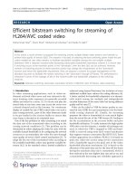
largest one, and so on. For example, Figure 2(a) shows the
coding sequence where 4 hierarchical trees are included and
each tree has 3 bit-planes. It is seen from this figure that there
are 7 bit-planes totally to be selected/coded for transmission.
However, it is easy to see that such arrangement will run
into problem in practice. As the bit-plane N
− 1ofT
2
is not
selected, all bits received for the bit-plane N
− 2ofT
2
are not
decodable. Similarly, as the bit-plane N
− 2 is selected before
the bit-plane N in T
3
, all bits in the bit-plane N − 2ofT
3
may become undecodable if it happens that some bits in the
4 EURASIP Journal on Applied Signal Processing
Bit-plane N − 2
Bit-plane N
− 1
Bit-plane N
T
1
T
2
T
3
T
4
5
3
2
1
7
6
4
(a)
Bit-plane N − 2
Bit-plane N
− 1
Bit-plane N
T
1
T
2
T
3
T
4
5
2
1
7
64
3
(b)
Figure 2: (a) Coding sequence of one example with 4 trees. (b) Adjusted coding sequence of the same example.
bit-plane N of T
3
are not sent. Some adjustments are there-
fore necessar y. For this example, the correct coding sequence
after the adjustment is shown in Figure 2(b).
In practice, we need to compute S
l
(k), for each rate r
i
,
from the reconstructed frame F
i
(·) at each switching point.
Once the coding sequence is determined, we start the SPIHT
coding until the given budget B is used up. In this way, B
is une venly allocated over all hierarchical trees. The follow-
ing matrix shows the actual bit allocation (with the total
budget B
= 60 kilobits) for the video sequence “Akiyo” (Y-
component) at frame #15 (the original video sequence of CIF
format is coded using H.264 with QP
= 34 and the 9/7 filter
bank is used in the wavelet decomposition of 5 levels): it is
seen that the allocation is very uneven:
[BAM] =
b(u, v)
U×V
=
⎡
⎢
⎢
⎢
⎢
⎢
⎢
⎢
⎢
⎢
⎢
⎢
⎢
⎢
⎢
⎢
⎢
⎢
⎣
226 216 203 164 43 51 155 171 70 135 342
228 286 129 204 798 991 848 305 588 414 398
120 256 149 200 881 1138 835 448 469 352 405
87 184 181 158 2171 1504 1225 817 109 187 406
256 277 303 187 1592 1659 1191 609 90 171 385
129 139 381 834 1420 1261 1306 1060 674 148 329
145 129 1394 270 614 1633 1091 844 453 938 399
232 638 588 238 231 1602 1156 1033 330 1451 307
101 770 622 263 163 1208 3032 1340 1626 941 569
⎤
⎥
⎥
⎥
⎥
⎥
⎥
⎥
⎥
⎥
⎥
⎥
⎥
⎥
⎥
⎥
⎥
⎥
⎦
,(1)
with
b(u, v) = B.
Based on UCC, one bit allocation map [BAM]
i
can be
derived for each r
i
at a switching point. It is easy to see that
about 1 kilobit (12 bits for each element) is needed to loss-
lessly represent this map. It will be seen later on that [BAM]
i
may need to be sent (as overhead) during the switching from
one bit-stream to another.
2.2. Influence on coding of subsequent frames
What is the most important to us is that this SPIHT-based
processing of the reconstructed frame at each switching point
will unavoidably result in a different frame, and thus may
cause some quality drop. More severely, this might influence
the coding of all subsequent frames (up to the next I-frame).
1
1
It is important to notice that the same impact also happens in the SP-
frame coding scheme in H.264 when comparing against the coding with-
out SP-frames.
To understand how big this impact could be, we did many ex-
periments, with some results presented in the following (the
original video sequence is coded using H.264 with a QP value
specified in each figure).
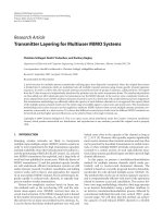
Figure 3 shows some results where there are 6 frames
(one for every 15 frames) specified as switching frames
among 100 frames of the “Akiyo,” “Foreman,” “Stefan,” and
“Mobile” sequences (all of CIF format and at 30 frames/
second), respectively. At each switching point, the recon-
structed frame after the H.264 coding is further processed
by SPIHT at B
= 53 + 6 + 6 kilobits (for Y , U,andV com-
ponents, resp.) for “Akiyo,” B
= 70 + 10 + 10 kilobits for
“Foreman,” B
= 140 + 10 + 10 kilobits for “Stefan,” and B =
200 + 15 + 15 kilobits for “Mobile,” respectively. The optimal
bit allocation strategy developed above is used in each SPIHT
processing, and the SPIHT processed frames at all switching
points are used in the coding of all subsequent frames.
It is seen from these results that all quality curves after
performing the SPIHT processing at each switching point
W. Zhang and B. Zeng 5
97857361493725131
Frame number
34
34.5
35
35.5
36
36.5
37
37.5
38
PSNR (dB)
Aykio
QP
= 32
SP
= 24
Opt65 k
97857361493725131
Frame number
31.5
32
32.5
33
33.5
34
34.5
35
35.5
PSNR (dB)
Foreman
QP
= 32
SP
= 24
Opt90 k
97857361493725131
Frame number
28
28.5
29
29.5
30
30.5
31
31.5
32
PSNR (dB)
Mobile
QP
= 32
SP
= 24
Opt230 k
97857361493725131
Frame number
30
30.5
31
31.5
32
32.5
33
33.5
34
PSNR (dB)
Stefan
QP
= 32
SP
= 24
Opt160 k
Figure 3: Coding quality deviations after six reconstructed frames are further coded using SPIHT.
(the white colored curves with small-triangle markers) do ex-
perience certain quality drop, compared to the correspond-
ing curves (the black curves without any markers) where all
frames (except for the first one) are coded as P-frames. While
the drop in “Akiyo” is quite noticeable (more than 1 dB), it is
well-controlled within 0.5 dB for other three sequences. An-
other interesting observation from Figure 3 is that the coding
quality drop at one switching point does not seem to add up
with others at all switching points thereafter for “Foreman,”
“Stefan,” and “Mobile,” whereas this adding-up effect seems
to be existing slightly in “Akiyo.”
Figure 3 also includes the corresponding results (the dark
grey colored curves with small-diamond markers) obtained
by doing a requantization in the DCT domain—the same as
was used in H.264 to generate the primary SP-frames [7–
10], where the requantization factor SPQP is set at 24. It is
clear that the SP-frame scheme yields results that are better
than our results for the “Akiyo” sequence, about the same
for the “Foreman” sequence, but slightly worse for the “Ste-
fan” and “Mobile” sequences. In the meantime, it is worth to
point out that the coding quality drop shown in Figure 3 is
much smaller when comparing with what is experienced in
the FGS coding (i.e., usually 3 dB). A comparison between
the bit budget used in the SPIHT processing and the size
of each secondary SP-frame generated in H.264 will be pre-
sented in the next section.
3. A TRIVIAL SWITCHING ARRANGEMENT
After the switching frame F
i
(t
0
) is further processed using
the SPIHT algorithm for each rate r
i
so as to obtain the mod-
ified version
¯
F
i
(t
0
), a trivial switching mechanism between
two bit-streams can be arranged as in Figure 4.
Suppose that the bit-stream at rate r
i
is currently
streamed and a switching to the rate r
j
is needed right at
the preselected point t
0
. Then, the transmitted video fr ames
around the switching point are
{F
i
(t
0
− 1),
¯
F
j
(t
0
), F
j
(t
0
+
1)
}. From our earlier analysis, we can see that the number
of bits used for representing
¯
F
j
(t
0
) is about 1 kilobit + B
j
,
where B
j
is the total bit budget allowed at each switching
6 EURASIP Journal on Applied Signal Processing
r
j
r
i
IPPP
···
···
···
···
F
i
(t
0
− 1) F
i
(t
0
) F
i
(t
0
) F
i
(t
0
+1)
Figure 4: A trivial switching arrangement between two bit-streams.
point to SPIHT-code F
j
(t
0
) into
¯
F
j
(t
0
), and about 1 kilobit
is needed to represent [BAM]
j
(as F
j
(t
0
) is not available at
the switching point—we need to know [BAM]
j
so that all
received bits for representing
¯
F
j
(t
0
) can be correctly parti-
tioned among all hierarchical trees). On the other hand, the
transmitted frames are
{F
i
(t
0
− 1), F
i
(t
0
)/
¯
F
i
(t
0
), F
i
(t
0
+1)} if
no switching happens at t
0
. It is important to notice that the
SPIHT processing on F
i
(t
0
)soastogenerate
¯
F
i
(t
0
)doesnot
require any extr a bits to be sent, because the same processing
can be done at the receiver side.
Comparing with the SP-frame sw itching method in
H.264, we see that the frame
¯
F
j
(t
0
) plays the role of an SP-
frame at the switching point when a switching from r
i
to
r
j
indeed happens. Furthermore, it is interesting to notice
that
¯
F
j
(t
0
) also plays the role of an SI-frame for the pur-
pose of splicing and random access/browsing. According to
our earlier analysis, the bit count for a switching frame is
about 1 kilobit plus the selected budget. For all test sequences
used above, we have run H.264 to generate all secondary SP-
frames under the same configuration as used in Figure 3,
and Table 1 presents the sizes of these secondary SP-frames
at each preselected switching point for switching between
QP
= 28 and QP = 36, with SPQP = 24. In fact, we have
referred to the bit-counts listed in Tab le 1 to choose the bud-
get B used above in the SPIHT processing of each switching
frame so that B is always significantly (15%–30%) smaller
than the size of the corresponding secondary SP-frame.
In the direct switching scheme, the frames to be trans-
mitted for the switching from r
i
to r
j
at the switching point
t
0
is {F
i
(t
0
− 1), F
j
(t
0
), F
j
(t
0
+1)}. Thus, the bit set Z
j
(t
0
)
needs to be sent right at the switching point t
0
.Inmost
coding applications, C
j
(t
0
)—the bit count in Z
j
(t
0
)would
be much smaller than B
j
. For instance, the typical value of
C
j
(t
0
) is about 2–4 kilobits in the coding of video sources of
30 frames/second at 128 kilobits/second, whereas B
j
is usu-
ally several tens of kilobits.
Another feature of this trivial switching arrangement is
that two reconstructed frames are independently processed
(using SPIHT) according to their individual budgets. In real-
ity, however, we know that there typically exists a strong sim-
ilarity between these two reconstructed frames so that a joint
processing seems more appropriate. Such a joint processing
will be presented in the next section.
4. JOINT PROCESSING OF SWITCHING
FRAMES AT TWO BIT-RATES
We only consider the switching between two non-scalable
bit-streams in this section, while the extension to multiple
(more than two) bit-streams is discussed later in Section 5.
In this scenario, we feed both reconstructed frames at each
preselected switching point into a joint SPIHT-typ e process-
ing, as shown in Figure 5.
The upper part outlined by the dash-line box is the non-
scalable coding of a source video at the higher bit-rate r
H
,and
the corresponding coding at the lower bit-rate r
L
is shown
in the bottom part. After the reconstruction, however, two
coded versions at bit-rates r
H
and r
L
are fed into the joint
SPIHT box for some extra processing, as outlined in the fol-
lowing.
Step 1. Both F
H
(t
0
)andF
L
(t
0
) at a preselected switching
point t
0
undergo the same wavelet decomposition with the
maximum depth (e.g., 5 levels are needed in the CIF format)
to generate all hierarchical trees T
H
(u, v)andT
L
(u, v)(e.g.,
there are totally 9
× 11 = 99 hierarchical trees in the CIF
format).
Step 2. The SPIHT coding is perfor med on F
H
(t
0
)andF
L
(t
0
),
respectively, according to their bit allocation maps [ BAM]
H
and [BAM]
L
that can be derived from the allowed total bud-
gets B
H
and B
L
. After the SPIHT coding, each hierarchical
tree is denoted as
¯
T
H
(u, v)or
¯
T
L
(u, v), with length b
H
(u, v)
or b
L
(u, v), respectively.
Step 3. We start a joint processing on two coded hierarchical
trees
¯
T
H
(u, v)and
¯
T
L
(u, v)(foreach(u, v)) by representing
the difference between them.
Some explanations are in order. First of all, the coding
of all subsequent frames a fter a switching point t
0
is based
on the modified versions of F
H
(t
0
)andF
L
(t
0
), that is,
¯
F
H
(t
0
)
and
¯
F
L
(t
0
), as shown in Figure 5, no matter whether a switch-
ing indeed happens or not at t
0
during streaming. This usu-
ally will cause s ome quality drop. From our study presented
in Section 2, such quality drop has been controlled within a
small level. Secondly, when no switching happens at time t
0
,
the frame F
H
(t
0
)orF
L
(t
0
) reconstructed at the decoder side
has to undergo the same (as what is done at the encoder side)
wavelet compression so as to generate
¯
F
H
(t
0
)or
¯
F
L
(t
0
)(for
synchronizing the encoder and the decoder). In practice, this
is doable as we know the budget B
H
or B
L
at the decoder side
so that the same [BAM]
H
or [BAM]
L
can be derived. Thus,
zero overhead bits are needed if no switching happens at t
0
.
Thirdly, all bits representing the difference between
¯
F
H
(t
0
)
and
¯
F
L
(t
0
) need to be sent as overhead when a switching be-
tween r
L
and r
H
does happen at t
0
.
The block diagram of representing the difference between
¯
F
H
(t
0
)and
¯
F
L
(t
0
) (during the SPIHT coding process of indi-
vidual hierarchical trees) is as simple as shown in Figure 6,
with principle as follows: (1) a bit 0 is recorded if the first cor-
responding bits of
¯
T
H
(u, v)and
¯
T
L
(u, v) are the same, and we
continuously record the bit 0 if the following corresponding
W. Zhang and B. Zeng 7
Table 1: Bit counts of the secondary SP frames in various test sequences.
Sequence Switching direction Switching #1 Switching #2 Switching #3 Switching #4 Switching #5 Switching #6
Akiyo
QP: 28
→ 36 72, 600 73, 688 73, 656 73, 336 74, 848 73, 416
QP: 36
→ 28 74, 376 75, 440 75, 384 75, 152 76, 696 75, 216
Foreman
QP: 28
→ 36 112, 600 111, 240 107, 496 113, 408 107, 2484 117, 392
QP: 36
→ 28 117, 448 115, 600 111, 632 117, 872 111, 776 123, 304
Stefan
QP: 28
→ 36 199, 288 196, 504 199, 240 194, 160 194, 520 203, 424
QP: 36
→ 28 207, 176 203, 688 208, 816 205, 504 207, 120 216, 504
Mobile
QP: 28
→ 36 254, 584 251, 600 254, 784 257, 600 265, 888 272, 720
QP: 36
→ 28 275, 456 272, 768 274, 432 280, 352 288, 888 296, 200
Bit-stream
at rate r
H
Bit-stream
at rate r
L
I
PPPSF
Joint
SPIHT
Extra
bit-stream
IP PPSF
F
H
(t
0
) F
H
(t
0
)
F
L
(t
0
)
F
L
(t
0
)
Figure 5: Joint SPIHT processing of two reconstructed frames at
each switching point.
bits of
¯
T
H
(u, v)and
¯
T
L
(u, v) are also the same (e.g., the first
5bits of
¯
T
H
(u, v)and
¯
T
L
(u, v), shown by the concatenated
squares in Figure 6); and (2) as long as we observe that the
corresponding bits of
¯
T
H
(u, v)and
¯
T
L
(u, v) are not the same
for the first time, all remaining bits of
¯
T
H
(u, v) (the white col-
ored horizontal bar shown in Figure 6) are recorded into the
box denoted as “extra bit-stream for switching up” (i.e., from
r
L
to r
H
); while all remaining bits of
¯
T
L
(u, v) (the gray colored
horizontal bar shown in Figure 6) are recorded into the box
denoted as “extra bit-stream for switching down” (i.e., from
r
H
to r
L
).
Because both F
L
(t
0
)andF
H
(t
0
) are coded from the same
original frame F(t
0
), there exists a high degree of similarity
between them. Thus, a lot of leading bits in the coding of two
corresponding hierarchical trees T
H
(u, v)andT
L
(u, v)would
be the same for each (u, v). In practice, instead of sending
these leading 0 bits (as deleted by a big cross in Figure 6),
we use an integer N(u, v) to represent the runlength so as
to achieve a much higher efficiency. In our simulations, we
observed that the number of these same leading bits is often
quite large, with the maximum and average being about 250
and 60, respectively, which thus can be fully covered by 8 bits.
No matter a switching between r
L
and r
H
indeed hap-
pens or not at t
0
during the practical streaming service, we
always send the bit set Z
L
(t
0
)orZ
H
(t
0
) (needing C
L
(t
0
)or
C
H
(t
0
) bits, resp.) so that we know either F
L
(t
0
)orF
H
(t
0
)
at this switching point. Obviously, zero overhead bits are
needed if no switching happens at t
0
.However,weneedto
Extra bit-stream
for switching up
Extra bit-stream
for switching
down
Bit/symbol
comparison
T
H
(u, v)
−→
F
H
(t
0
)
b
H
(u, v)
b
L
(u, v)
T
L
(u, v)
−→
F
L
(t
0
)
=
N(u, v)
Figure 6: Block diagram for the joint SPIHT processing of two
coded frames at a switching point.
use the reconstructed F
L
(t
0
)orF
H
(t
0
) to compute the bit
allocation map [BAM]
L
or [BAM]
H
according to the given
total budget B
L
or B
H
(as discussed in Section 2), and then
F
L
(t
0
)orF
H
(t
0
) needs to go through the SPIHT processing
so as to generate
¯
F
L
(t
0
)or
¯
F
H
(t
0
).
On the other hand, if a switching does happen at t
0
,we
still can compute one bit allocation map [BAM]
L
or [BAM]
H
(as either F
L
(t
0
)orF
H
(t
0
) is also available), while the other
map needs about 1 kilobit (as overhead) to represent.
2
Then,
F
L
(t
0
)orF
H
(t
0
) goes through the SPIHT processing accord-
ing to the computed bit allocation map. However, we only
keep the first N(u, v) bits during the SPIHT coding of its
(u, v)th hierarchical tree. According to our earlier discus-
sion, these first N(u, v) bits are the same in the coding of
the (u, v)th hierarchical t ree of both F
L
(t
0
)andF
H
(t
0
), while
N(u, v) itself needs 8 bits to represent. Therefore, we can de-
rive that the total number of bits to be sent for a switching
is
H→L(or L→H)
= E + B
L(or H)
+ C
H(or L)
t
0
+8· (U × V) −
N(u, v),
(2)
where E denotes the number of bits used to represent the dif-
2
Alternatively, we can represent the difference between these two maps so
as to reduce the overhead bit count, and this strategy has been adopted in
our system.
8 EURASIP Journal on Applied Signal Processing
r
3
r
2
r
1
···
···
···
···
···
···
F
i
(t
0
) −→ F
i
(t
0
)
Figure 7: Switching among three bit-streams at the preselected
point.
ference between [BAM]
L
and [BAM]
H
(which is now smaller
than 1 kilobit for the CIF format), and U
= 9andV = 11
for the CIF format. It is clear that this new switching ar-
rangement becomes more efficient than the trivial switch-
ing mechanism presented in Section 3 as long as
N(u, v) >
E + C
H(or L)
(t
0
)+8· (U × V) − 1 kilobit.
5. SWITCHING AMONG MULTIPLE BIT-STREAMS
For switching among more than two bit-streams coded at
rates r
i
, i = 1, 2, , M, each reconstructed frame F
i
(t
0
) at the
switching point t
0
is coded using SPIHT at the selected bud-
get B
i
so as to generate
¯
F
i
(t
0
). Then, the trivial switching ar-
rangement developed in Section 3 can be extended readily to
this multiple bit-rate case, see Figure 7 for an example where
M
= 3 and only one switching point is included. Clearly, this
arrangement allows any arbitrary switching, that is, between
rate r
i
and rate r
j
for all j = i. As discussed in Section 3,
the total number of bits to be sent is about 1 kilobit + B
i
if a
switching from any rate to r
i
indeed happens at a preselected
switching point t
0
. As discussed in Section 4, this number
could be f urther reduced by using the joint SPIHT processing
between r
i
and r
j
. Therefore, the joint processing will be en-
forced at a switching point only when it can reduce the count
of overhead bits that needs to be sent. On the other hand,
no overhead bits are sent if no switching happens at t
0
:only
the bit set Z
i
(t
0
) needs to be sent, whereas the correspond-
ing SPIHT needs to be p erformed at the decoder side so as to
generate
¯
F
i
(t
0
).
It is clear from Figure 7 that we need to store a number of
M extra frames
¯
F
i
(t
0
), i = 1, 2, , M, at the video server, to
support any arbitrary switching between r
i
and r
j
for all j =
i. On the other hand, there are totally M · (M − 1) secondary
SP-frames that need to be generated and stored at the server
in the SP-frame switching scheme to support any arbitrary
switching—which is obviously very disadvantageous.
Compared to the scheme proposed in [15]whereanew
bit-stream (called the S-stream) is generated at each switch-
ing point and it will be selected when a switching indeed
happens at this point, each switching frame in our method
is generated in the intra-coding manner. As a result, each
switching frame generated in our method ser ves both the
switching task and the purpose of random access and brows-
ing. Furthermore, it has been demonstrated in [9] that each
S-stream is less efficient than the corresponding SP-frame
switching, whereas some results will be presented in the next
section to show that our switching scheme provides a bet-
ter rate-distortion performance than the SP-frame switch-
ing.
In principle, we should select different bit budget B
i
for different rate r
i
in the implementation of our switching
scheme. In reality, however, it is r ather difficult to establish
an accurate relationship between them. For instance, it is not
necessarily true that a smaller budget should be used for a
smaller rate. In our H.264-based experiments, we observed
that, in the switching-down case, the size of the secondary
SP-frame for switching from the maximum rate to the min-
imum rate is actually larger than that of the corresponding
secondary SP-frame for switching from the same maximum
rate to any of other lower rates (not the minimum one). This
result seems to be rather absurd: more overhead bits need to
be sent when a bigger bandwidth drop is detected! In fac t,
how to handle this problem is left over as one of our future
works.
For simplicity, we choose the budget B
i
for each rate
based on the sizes of the corresponding secondary SP-frames.
For example, for r
i
, there are M − 1 switching-in cases (from
r
j
for all j = i) at each switching point. Then, we run H.264
with a selected SPQP to obtain the sizes of all M
− 1sec-
ondary SP-frames, and choose B
i
at a number that is slightly
smaller than the minimum size. In general, for each r
i
, this
will result in different B
i
at different switching points. In our
simulations, however, we try to ignore this variation and thus
use the same B
i
at all switching points.
6. EXPERIMENTAL RESULTS AND ANALYSIS
In this section, we provide some experimental results to
illustrate the coding efficiency of our proposed switching
method. In our simulations, 5 bit-streams are generated by
using H.264 at different Q P factors: QP5
= 24, QP4 = 28,
QP3
= 32, QP 2 = 36, and QP1 = 40, respectively. Over-
all, 100 frames are encoded, with the first frame as I-frame
and the rest of them as P-frames. Then, six switching points
are selected at #15, #30, #45, #60, #75, and #90, respectively.
The switching arrangement is similar to the one shown in
Figure 7, while the 9/7 filter bank is used to perform the
wavelet decomposition of 5 levels.
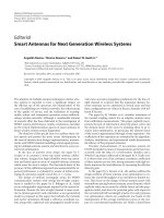
Figure 8 shows the results in terms of luminance PSNR
for the “Foreman” and “Stefan” sequences, while Tab le 2
lists the bit budgets used to obtain these results in which
20 kilobits are used for the U and V components and the re-
maining is for the Y component. It should be pointed out
that these budgets are determined by referring to the sizes of
the corresponding secondary SP-frames obtained in running
H.264 with a fixed SPQP at 24 for all rates (see the discus-
sions at the end of Section 5 ). Thus, different budgets may be
used if other SPQP values are used to generate SP-frames.
For each of these two sequences, the first plot shows the
monotonic switching-up scenario, the second one shows the
W. Zhang and B. Zeng 9
9686766656463626166
Frame number
27
29
31
33
35
37
39
41
PSNR (dB)
Foreman
QP
= 40
QP
= 36
QP
= 32
QP
= 28
QP
= 24
Switchup
SP
= 24
9686766656463626166
Frame number
27
29
31
33
35
37
39
41
PSNR (dB)
Foreman
QP
= 40
QP
= 36
QP
= 32
QP
= 28
QP
= 24
Switchdown
SP
= 24
9686766656463626166
Frame number
27
29
31
33
35
37
39
41
PSNR (dB)
Foreman
QP
= 40
QP
= 36
QP
= 32
QP
= 28
QP
= 24
Alternate
SP
= 24
9686766656463626166
Frame number
27
29
31
33
35
37
39
41
PSNR (dB)
Foreman
QP
= 40
QP
= 36
QP
= 32
QP
= 28
QP
= 24
Random
SP
= 24
9686766656463626166
Frame number
25
27
29
31
33
35
37
39
PSNR (dB)
Stefan
QP
= 40
QP
= 36
QP
= 32
QP
= 28
QP
= 24
Switchup
SP
= 24
9686766656463626166
Frame number
25
27
29
31
33
35
37
39
PSNR (dB)
Stefan
QP
= 40
QP
= 36
QP
= 32
QP
= 28
QP
= 24
Switchdown
SP
= 24
9686766656463626166
Frame number
25
27
29
31
33
35
37
39
PSNR (dB)
Stefan
QP
= 40
QP
= 36
QP
= 32
QP
= 28
QP
= 24
Alternate
SP
= 24
9686766656463626166
Frame number
25
27
29
31
33
35
37
39
PSNR (dB)
Stefan
QP
= 40
QP
= 36
QP
= 32
QP
= 28
QP
= 24
Random
SP
= 24
Figure 8: Four switching scenarios among five bit-streams of “Foreman” and “Stefan.”
10 EURASIP Journal on Applied Signal Processing
Table 2: Budgets (in kilobits) used in our simulations—same at all switching points.
Sequence QP = 40 QP = 36 QP = 32 QP = 28 QP = 24
Foreman 75+10+10 75+10+10 70+10+10 60+10+10 65+10+10
Stefan 170 + 10 + 10 160 + 10 + 10 120 + 10 + 10 120 + 10 + 10 130 + 10 + 10
Table 3: Sizes of secondary SP-frames to be sent at each switching point (in bits).
Sequence Scenario #1 #2 #3 #4 #5 #6
Foreman
Up 109, 792 101, 880 97, 664 96, 496 — —
Down 95, 584 96, 920 98, 672 105, 992 — —
Alternate 142, 504 136, 968 139, 120 137, 688 137,680 143, 512
Random 116,896 144, 472 103, 904 117,352 103, 552 110, 256
Stefan
Up 202, 272 185, 920 177, 936 156,176 — —
Down 159, 504 169, 104 185,688 195, 208 — —
Alternate 239, 224 233, 576 251, 232 228, 912 253,576 237, 504
Random 207,408 244, 616 177, 800 209,608 198, 024 200, 424
monotonic switching-down scenario, the third one shows
the alternate switching scenario between the minimum rate
and the maximum rate, and the fourth one shows a sce-
nario of random switching (both up and down). Five black
orwhitecurveswithoutmarkersinFigure 8 represent the
H.264-coded results with all frames (except for the first one)
coded as P-frames. Therefore, it is expected that the qual-
ity curve after inserting some switching points will always be
(slightly) worse. However, it is seen from Figure 8 that the
results achieved in our switching scheme (the white curves
with small cross markers) are nearly perfect at all switching
points for both sequences.
Figure 8 also presents the results obtained by using the
SP-frame switching scheme (the dark grey curves with small
triangle markers), and Ta ble 3 summarizes the sizes of the
corresponding secondary SP-frames that need to be sent at
each switching point. It is seen that while the resulting qual-
ity curves a re nearly the same as our results, the SP-frame
switching scheme requires many more bits to be sent at each
switching point.
7. CONCLUSIONS AND FUTURE WORKS
Multirate representation seems to be one efficient solution to
the v ideo streaming service over heterogeneous and dynamic
networks. In this paper, we developed an effective method
that allows seamless switching among different bit-streams
in multirate based streaming systems when a channel band-
width change is detected. The unique feature of our method
is that, at a preselected switching point, the reconstructed
frameateachrateortworeconstructedframesatdiffer-
ent rates need undergo through an independent or a joint
SPIHT-type processing in the wavelet domain in which an
optimal bit allocation over all hierarchical trees has been ap-
plied. Compared with the SP-fr ame switching scheme, our
method proves to be able to achieve the seamless switching
at a better rate-distortion performance.
Our future works will be focusing on how to handle the
switching-down case more effectively so that much fewer bits
need to be sent in this scenario. On the other hand, we know
that the SPIHT coding plays a critical role in our switching
scheme. Although SPIHT itself is quite efficient, trying to fur-
ther increase the coding efficiency is also one of our future
works. In the meantime, we will also consider other popu-
lar ways to accommodate possible bandw idth changes, such
as frame-skipping and down-sizing, so as to facilitate a more
practical streaming system.
ACKNOWLEDGMENTS
This work has been supported partly by a DAG research grant
from HKUST and a RGC research grant from HKSAR. We
would like to thank Dr. Xiaoyan Sun of Microsoft Research
Asia for helping us get the bit-counts listed in Tables 1, 2,
and 3.
REFERENCES
[1] ISO/IEC 14496-2, “Coding of audio-visual objects, part-2: vi-
sual,” December 1998.
[2] W. Li, “Overview of fine granularity scalability in MPEG-4
video standard,” IEEE Transactions on Circuits and Syste ms for
Video Technology, vol. 11, no. 3, pp. 301–317, 2001.
[3] F. Wu, S. Li, and Y Q. Zhang, “A framework for efficient pro-
gressive fine granularity scalable video coding,” IEEE Trans-
actions on Circuits and Systems for Video Technology, vol. 11,
no. 3, pp. 332–344, 2001.
[4] D. Wu, Y. T. Hou, W. Zhu, Y Q. Zhang, and J. M. Peha,
“Streaming video over the internet: approaches and direc-
tions,” IEEE Transactions on Circuits and Systems for Video
Technology, vol. 11, no. 3, pp. 282–300, 2001.
[5] G. J. Conklin, G. S. Greenbaum, K. O. Lillevold, A. F. Lippman,
and Y. A. Reznik, “Video coding for streaming media delivery
on the internet,” IEEE Transactions on Circuits and Syste ms for
Video Technology, vol. 11, no. 3, pp. 269–281, 2001.
W. Zhang and B. Zeng 11
[6] J. Lu, “Signal processing for internet video streaming: a re-
view,” in Image and Video Communications and Processing,
vol. 3974 of Proceedings of SPIE, pp. 246–259, San Jose, Calif,
USA, January 2000.
[7] M. Karczewicz and R. Kurceren, “A proposal for SP-frames,” in
ITU-T Video Coding Experts Group Meeting, Eibsee, Germany,
January 2001, Doc. VCEG-L-27.
[8] M. Karczewicz and R. Kurceren, “Improved SP-frame encod-
ing,” in ITU-T Video Coding Experts Group Meeting, Austin,
Tex, USA, April 2001, Doc. VCEG-M-73.
[9] M. Karczewicz and R. Kurceren, “The SP- and SI-frames de-
sign for H.264/AVC,” IEEE Transactions on Circuits and Sys-
tems for Video Technology, vol. 13, no. 7, pp. 637–644, 2003.
[10] X. Sun, S. Li, F. Wu, G. Shen, and W. Gao, “Efficient and flex-
ible drift-free video bitstream switching at predictive frames,”
in Proceedings of IEEE International Conference on Multimedia
and Expo (ICME ’02), Lausanne, Switzerland, August 2002.
[11] ITU-T Rec. H.264
| ISO/IEC 14496-10 (AVC), “Advanced
video coding for generic audiovisual services”, March 2005.
[12] E. Setton and B. Girod, “Video streaming with SP and
SI frames,” in Visual Communications and Image Processing
(VCIP ’05), vol. 5960 of Proceedings of SPIE, pp. 2204–2211,
Beijing, China, July 2005.
[13] E. Setton, P. Ramanathan, and B. Girod, “Rate-distortion anal-
ysis of SP and SI frames,” in Proceedings of IEEE Interna-
tional Conference on Image Processing (ICIP ’05), Genova, I taly,
September 2005.
[14] X. Sun, F. Wu, S. Li, W. Gao, and Y Q. Zhang, “Seamless
switching of scalable video bitstreams for efficient streaming,”
IEEE Transactions on Multimedia, vol. 6, no. 2, pp. 291–303,
2004.
[15] N. Farber and B. Girod, “Robutst H.263 compatible video
transmission for mobile access to video servers,” in Proceed-
ings of IEEE International Conference on Image Processing
(ICIP ’97), Santa Barbara, Calif, USA, October 1997.
[16] A. A. Said and W. A. Pearlman, “New, fast, and efficient im-
age codec based on set partitioning in hierarchical trees,”
IEEE Transactions on Circuits and Systems for Video Technol-
ogy, vol. 6, no. 3, pp. 243–250, 1996.
Wei Zhang received the B.Eng. and M.Phil.
degrees in electronic engineering from
Hong Kong University of Science and Tech-
nology, Hong Kong, in 2003 and 2006, re-
spectively. Her research interests include
video/image coding and video streaming.
Bing Zeng joined the Hong Kong Uni-
versity of Science and Technology in 1993
and is currently an Associate Professor at
the Depart ment of Electrical and Electronic
Engineering. His general research interests
include digital signal and image process-
ing, linear and nonlinear filter design, and
image/video coding and transmission. His
most recent research focus is on some fun-
damental issues in image/video coding such
as directional transform, truly optimal rate allocation, and smart
motion estimation/compensation, as well as various solutions
for real-time video streaming applications over the Internet and
wireless networks. His research efforts in these areas have pro-
duced over 150 journal and conference publications. He received
the B.Eng. and M.Eng. degrees from the University of Electronic
Science and Technology of China in 1983 and 1986, respectively,
and the Ph.D. degree from Tampere University of Technology, Fin-
land, in 1991, all in electrical engineering. He worked as a Postdoc-
toral Fellow at the University of Toronto and Concordia University
during 1991–1993 and was a Visiting Researcher at Microsoft Re-
search Asia, Beijing, China, in 2000. He was an Associate Editor for
the IEEE Transactions on Circuits and Systems for Video Technol-
ogy during 1995–1999 and served in various capacities in a number
of international conferences. He is currently a Member of the Vi-
sual Signal Processing & Communications Technical Committee of
IEEE CAS Society.