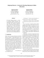
Báo cáo hóa học: " Intra-Symbol Windowing for Egress Reduction in DMT Transmitters" pptx
Bạn đang xem bản rút gọn của tài liệu. Xem và tải ngay bản đầy đủ của tài liệu tại đây (1.27 MB, 9 trang )
Hindawi Publishing Corporation
EURASIP Journal on Applied Signal Processing
Volume 2006, Article ID 70387, Pages 1–9
DOI 10.1155/ASP/2006/70387
Intra-Symbol Windowing for Egress Reduction
in DMT Transmitters
Gert Cuypers,
1
Koen Vanbleu,
2
Geert Ysebaert,
3
and Marc Moonen
1
1
ESAT/SCD-SISTA, Katholieke Universiteit Leuven, 3001 Heverlee, Belgium
2
Broadcom Corporation, 2800 Mechelen, Belgium
3
Alcatel Bell, 2018 Antwerp, Belg ium
Received 28 December 2004; Revised 20 July 2005; Accepted 22 July 2005
Discrete multitone (DMT) uses an inverse discrete Fourier transform (IDFT ) to modulate data on the carriers. The hig h sidelobes
of the IDFT filter bank used can lead to spurious emissions (egress) in unauthorized frequency bands. Applying a window func-
tion within the DMT symbol can alleviate this. However, window functions either require additional redundancy or will introduce
distortions that are generally not easy to compensate for. In this paper, a special class of window functions is constructed that
corresponds to a precoding at the transmitter. These do not require any additional redundancy and need only a modest amount of
additional processing at the receiver. The results can be used to increase the spectral containment of DMT-based wired communi-
cations such as ADSL and VDSL (i.e., asymmetric, resp., very-high-bitrate digital subscr iber loop).
Copyright © 2006 Gert Cuypers et al. This is an open access article distributed under the Creative Commons Attribution License,
which permits unrestricted use, distribution, and reproduction in any medium, provided the original work is properly cited.
1. INTRODUCTION
Discrete Fourier transform (DFT-) based modulation tech-
niques [1] have become increasingly popular for high-speed
communications systems. In the wireless context, for exam-
ple, for the digital transmission of audio and video, this is
usually referred to as orthogonal frequency-division multi-
plexing (OFDM). Its wired counterpart has been dubbed dis-
crete multitone (DMT), and is employed, for example, for
digital subscriber loop (DSL) systems, such as asymmetric
DSL (ADSL) and very-high-bitrate DSL (VDSL).
A high bandwidth efficiency is achieved by dividing the
available bandwidth into small frequency bands centered
around carriers (tones). These carriers are individually mod-
ulated in the frequency domain, using the inverse DFT
(IDFT). A cyclic prefix (CP) is added to the resulting block
of time-domain samples by copying the last few samples and
putting them in front of the symbol [2]. This extended block
is parallel-to-serialized, passed to a digital-to-analog (DA)
convertor and then transmitted over the channel. At the re-
ceiver, the signal is sampled and serial-to-parallelized again.
The part corresponding to the CP is discarded, and the re-
mainder is demodulated using the DFT.
In case the order of the channel impulse response does
not exceed the CP length by more than one, equalization can
be done easily using a one-tap frequency-domain equalizer
(FEQ) for each tone, correcting the phase shift and attenu-
ation at each tone individually. When the channel impulse
response is longer than the CP, the transmission suffers from
intercarrier interference (ICI) and intersymbol interference
(ISI), requiring more complex receivers, for example, a per-
tone equalizer (PTEQ) [3]. The windowing technique pre-
sented in this article is irrespective of the equalization tech-
nique used but can be combined with the PTEQ in a very
elegant way.
In addition to a CP, VDSL systems can also use a cyclic
suffix(CS).Thedifference between the CP and CS is irrel-
evant to this article, therefore they will be treated as one
(larger) CP. More importantly, the presence of the CP influ-
ences the spectrum of the transmit signal, as will be shown
later.
While DMT seems attractive because of its flexibility
towards spectrum control, the high sidelobe levels associ-
ated with the DFT filter bank form a serious impediment,
resulting in an energy transfer between in-band and out-
of-band signals. This contributes to the crosstalk, for ex-
ample, between different pairs in a binder, especially for
next-generation DSL systems using dynamic spectrum man-
agement (DSM), where the transmit band is variable [4].
Moreover, because the twisted pair acts as an antenna [5],
there exists a coupling with air signals. The narrowband
signals from, for example, an AM broadcast station can
2 EURASIP Journal on Applied Signal Processing
X
(k)
0
.
.
.
X
(k)
N
−1
γ
βα
IDFT
ADD
CP
P/S D/A H
+
AWG N
A/D S/P DFTDFT PTEQ
Z
(k)
0
.
.
.
Z
(k)
N
−1
Figure 1: Basic DMT system (refer to text for α to γ).
be picked up by the receiver and, due to the sidelobes, be
smearedoutoverabroadfrequencytonerange.Thisprob-
lem has been recognized, and various schemes have been de-
veloped to tackle it (see [6–8]). On the other hand, the same
poor spectral containment of transmitted signals makes it
difficult to meet egress norms, for example, the ITU-norm
[9] specifies that the transmit power of VDSL should b e low-
ered by 20 dB in the amateur radio bands. Controlling egress
is usually done in the frequency domain by combining neigh-
bouring IDFT-inputs (such as in [10]) or, equivalently, by
abandoning the DFT altogether and reverting to other filter
banks, such as, for example, in [11].
Another approach would be to apply an appropriate
time-domain window (see [12] for an overview) at the trans-
mitter. Unfortunately, the application of nonrectangular
windows destroys the orthogonality between the tones, re-
sulting in ICI. In [13], a windowed VDSL system is proposed,
where the window is applied to additional cyclic continua-
tions of the DMT symbol to prevent distorting the symbol
itself.
The technique proposed in this article avoids the over-
head resulting from such additional symbol extension by
applying the window directly to the DMT symbol, that is,
without adding additional guard bands. This windowing
is observed to correspond to a precoding operation at the
transmitter. Obviously, this alters the frequency content at
each carr ier, such that a correction at the receiver is needed.
While this compensation is generally nontrivial [14], we con-
struct a class of windows that can be compensated for with
only a minor amount of additional computations at the re-
ceiver .
When investigating transmit windowing techniques, it
is important to have an accurate description of the trans-
mit spectrum of DMT/OFDM signals. Although DMT and
OFDM are commonplace, a lot of misconception and confu-
sion seem to exist with regard to the nature of their transmit
signal spectrum. When working on sampled channel data,
the continuous-time chara cter of the line sig nals is tra nspar-
ent, and therefore usually neglected. However, it is important
to realize that the behaviour in between the sample points
can be of great importance [15]. The analog signal will gen-
erally exceed the sampled points’ reach, possibly leading to
unnoticed clipping, and hence out-of-band radiation.
Therefore, Section 2 starts by describing the spectrum
of the classical DMT signal. The novel windowing system is
then presented in Section 3. Section 4 covers the simulation
results. Finally, in Section 5, conclusions are presented.
2. DMT TRANSMIT SIGNAL SPECTRUM
Consider the DMT system of Figure 1, with DFT-size N and
aCPlengthν, resulting in a symbol length L
= N + ν.The
symbol index is k and X
(k)
= [X
(k)
0
···X
(k)
N
−1
]
T
holds the
complex subsymbols at tones i, i
= 0:N − 1. In a base-
band system, such as ADSL, the time-domain signal is real-
valued, requiring that X
(k)
i
= X
(k)∗
N−i
. The corresponding dis-
crete time-domain sample vector (at point α in Figure 1)is
equal to
x
(k)
=
x
(k)
[0], , x
(k)
[L − 1]
T
,
x
(k)
[n] =
1
√
N
N−1
i=0
X
(k)
i
e
j(2πi/N)(n−ν)
, n = 0, , L − 1.
(1)
Note that the CP is automatically present, due to the peri-
odicity of the complex exponentials. The total discrete time-
domain sample stream x[n] is obtained as a concatenation
of the individual symbols x
(k)
. Interpolation of these samples
yields the continuous time-domain signal s(t), g iven by
s(t)
=
∞
τ=−∞
v(τ − t)
∞
n=−∞
δ(t − nT)x[n]
dτ,
x[ n]
=
1
√
N
∞
k=−∞
N−1
i=0
X
(k)
i
e
j(2πi/N)(n−ν−kL)
w
r,s
[n − kL],
(2)
with δ(t) the dirac impulse function, T the sampling period,
w
r,s
[n]a(rectangular, sampled) discrete time-domain win-
dow, w
r,s
[n] = 1for0≤ n ≤ L − 1 and zero elsewhere, and
v(t) an interpolation function.
The shape of the DMT spectrum will now be derived by
construction, starting from a single symbol with only one ac-
tive carrier at DC. This result will be extended to a succession
of symbols with all carriers excited. After this, the influence
of time-domain windowing will be investigated in Section 3.
Assume a sing le DMT symbol, having a duration L
=
N + ν in which only the DC component is excited (e.g., with
unit value), in other words,
X
(k)
i
=
⎧
⎨
⎩
1, i = 0, k = 0,
0, elsewhere.
(3)
The corresponding discrete time-domain signal is a sequence
of L identical pulses, which is equivalent to a multiplication
of a rectangular window and an impulse train (Figure 2). A
Gert Cuypers et al. 3
0
1
0 TL
− 1 L
t
Rectangular window w
r
(t)
Sampled window w
r,s
(t)
Interpolated window w
i
(t)
Next symbol
Figure 2: The first (DC only) symbol as a sampled rectangular win-
dow, and a possible next symbol.
0
L
−1/(2T)01/(2LT)1/(2T) f
|·|
|W
r,s
( f )|
|
W
r
( f )|
Figure 3: Spectrum of the continuous and sampled rectangular
window.
rectangular window w
r
(t) extending from t = 0tot = L has
a modulated sinc as its Fourier transform
W
r
( f ) =
sin(πLf )
πf
. exp(
−jπLf ). (4)
The multiplication of this w
r
(t) with a sequence of pulses
with period T results in the spectrum W
r
( f ) being convolved
with a pulse train with period 2π/T. The original sinc spec-
trum W
r
( f )andtheconvolvedspectrumW
r,s
( f ) are repre-
sented in Figure 3.Here,W
r,s
( f ) is periodic with a period
1/T. Surprisingly, this can be expressed analytically as [16]
W
r,s
( f ) =
sin(πLT f )
sin(πT f)
exp(
−jπLf ). (5)
In literature, W
r,s
( f ) is sometimes approximated by a sinc.
While this approximation is suitable for some applications,
it leads to an underestimate of the (possible egress) energy
in nonexcited frequency bands. More specifically, from (5), it
is clear that this leads to a maximum error of 3.9 dB around
f
=±1/2T.
∼ N
−1
∼ (N + ν)
−1
Frequency
PSD
Prefixless system
Prefix system
Single prefixless tone
Single tone with prefix
Figure 4: The cyclic prefix in DMT systems leads to a toothed spec-
trum exhibiting valleys in between the tones.
The final DA conversion consists of a lowpass filtering
with v(t), such that only the frequencies between
−1/T and
1/T are withheld. In the case of an ideal lowpass filter, this is
equivalent to a time-domain interpolation with a sinc func-
tion, resulting in w
i
(t), as shown in Figure 2. Note that the
continuous behaviour in between the sampled values is far
from constant.
This result can now be extended to describe a succes-
sion of multiple symbols (k
= 0, 1, ), with all tones (i =
0, 1, , N − 1) excited. Assume that the X
(k)
i
have a variance
E
|X
(k)
i
|
2
= σ
2
i
, and are uncorrelated. The power spectral den-
sity (PSD) S( f )ofs(t) can then be described as
S( f )
=
N−1
i=0
σ
2
i
W
r,s
f −
i
NT
·
V( f )
2
,(6)
with V( f ) the frequency characteristic of the interpolation
filter v(t) (an example of this is shown in Section 4 ).
Only in the case where the prefix is omitted (ν
= 0) and
the variances σ
2
i
= σ
2
are equal for all tones (except DC and
the Nyquist frequency, having only σ
2
/2), this spectrum is
more or less flat. In general, the CP results in a toothed spec-
trum. Indeed, because the symbols are lengthened by the CP,
the PSD of the individual tones is narrowed compared to
the intertone distance, such that “valleys” (or “teeth”) ap-
pear in between the tone frequencies. This is demonstrated in
Figure 4, where a detail of the spec trum of a prefixless DMT
system (ν
= 0) is compared to a system using a prefix.
3. TRANSMITTER WINDOWING
Practical lowpass filters are not infinitely steep, such that
some small signal components above the Nyquist frequency
will remain. The out-of-band performance is then largely de-
pendent on the quality of these filters (and possible clipping
in further analog stages). On the other hand, the in-band
4 EURASIP Journal on Applied Signal Processing
X
(k)
0
.
.
.
X
(k)
N
−1
Coding
C
IDFT
ADD
CP
P/S
H
+
AWG N
S/P
DFT
PTEQ
Decoding
D
Z
(k)
0
.
.
.
Z
(k)
N
−1
IDFT
Window
g
Figure 5: Transmitter windowing translates to symbol precoding.
transitions (e.g., for suppression of VDSL in the amateur ra-
dio bands) can only be sharpened by the application of a win-
dow function on the entire time-domain symbol. To achieve
this, the rectangular window w
r,s
[n] is replaced by another
one having faster decaying sidelobes. This new window
w
=
w(0) ···w(L −1)
T
(7)
is applied at point α in Figure 1. In the next paragraph we
impose constraints on w to construct a class of window func-
tions that are easy to compensate for at the receiver.
3.1. Derivation of the window structure
To preser ve the cyclic structure of the transmitted symbols,
needed for an easy equalization, we impose the cyclic con-
straint
w(n)
= w(n + N), n = 0, , ν − 1. (8)
As a result, instead of applying the window w at point α
(Figure 1), one c an also apply the window
g
=
g(0) ···g(N − 1)
T
=
w(ν) ···w(N + ν − 1)
T
(9)
at point β.LetG be a diagonal matrix with g as its diagonal.
After defining I
N
the IDFT-mat rix of size N, the vector of
windowed samples x
(k)
w
at point β (before the application of
the CP) can be written as
x
(k)
w
=
⎡
⎢
⎢
⎢
⎢
⎢
⎣
g(0) 0 ··· 0
0 g(1)
.
.
.
0
.
.
.
.
.
.
.
.
.
0
··· 0 g(n − 1)
⎤
⎥
⎥
⎥
⎥
⎥
⎦
G
I
N
· X
(k)
. (10)
As the product of a diagonal matrix and the IDFT-matrix is
equal to the product of the IDFT-matrix and a circulant ma-
trix, we can rewrite (10)as
x
(k)
w
= I
N
⎡
⎢
⎢
⎢
⎢
⎢
⎣
c(0) c(1) ··· c(N − 1)
c(N
− 1) c(0)
.
.
.
c(N − 2)
.
.
.
.
.
.
.
.
.
c(1)
··· c(0)
⎤
⎥
⎥
⎥
⎥
⎥
⎦
C
·X
(k)
. (11)
The circulant matrix C (“C” for coding) is fully defined by its
first row c
T
,with
c
=
c(0) ···c(N −1)
T
= I
N
· g, (12)
that is, IDFT of g. The transition from (10)to(11)ismore
than mathematical trickery. Looking at the DMT-scheme in-
corporating transmitter windowing of Figure 5,itbecomes
clear that the windowing operation in the time domain is
equivalent to the multiplication of the subsymbol vector X
(k)
with a (pre-)coding matrix C. Compensating for the window
at the receiver is now identical to a decoding in the frequency
domain, which is done by multiplication with the decod-
ing matrix D
= C
−1
(“D” for decoding), leaving the rest of
the sig nal path (equalization, etc.) unaltered. Thus, appeal-
ing windows should not only satisfy the constraint (8), but
preferably also give rise to a sparse decoding matrix D.We
will now further investigate the nature of such windows.
Being the inverse of a circulant matrix, D is also circulant.
We denote the first row of D as
d
T
=
d(0) ···d(N −1)
. (13)
Define F
N
the DFT-matrix of size N,and
f
=
f (0) · f (N − 1)
=
F
N
· d. (14)
It is now possible to associate to D a diagonal matrix F,hav-
ing on its diagonal the elements of f. The following relations
now hold:
(i) C and D are circular, with C
−1
= D,andhaveasafirst
row c
T
and d
T
,respectively;
(ii) G and F are diagonal, with diagonals g and f;
(iii) c
= I
N
· g;
(iv) d
= I
N
· f.
From this, we can conclude that F
= I
N
·D ·F
N
= I
N
·C
−1
·
F
N
= (I
N
· C · F
N
)
−1
= G
−1
. In other words,
g(n)
= f (n)
−1
, n = 0, , N − 1. (15)
Since g is real-valued, so is f. Consequently, d is the IDFT of a
real-valued vector. Because of the IDFT’s symmet ry proper-
ties, the first and middle elements of d are real-valued, and all
other nonzero elements appear in complex conjugate pairs.
Gert Cuypers et al. 5
We can now distinguish between three cases.
(i) A general d (nonsparse).
(ii) A maximally sparse d (with only three nonzero e le-
ments) is as follows:
d(n)
=
⎧
⎪
⎪
⎪
⎪
⎪
⎨
⎪
⎪
⎪
⎪
⎪
⎩
a, n = 0,
b
· e
jφ
, n = l,
b
· e
−jφ
, n = N − l,
0, n/
∈{0, l, N − l},
(16)
with
a, b real,
φ real
∈ [
−ππ
],
l integer
∈ [
1 N
− 1
],
(17)
so that
D
=
⎡
⎢
⎢
⎢
⎢
⎢
⎢
⎢
⎢
⎢
⎢
⎢
⎢
⎢
⎢
⎢
⎢
⎢
⎣
a 0 ··· 0 b · e
jφ
0 ···
0
.
.
.
.
.
.
.
.
.
0
b
· e
−jφ
0
.
.
.
.
.
.
.
.
.
0 a
⎤
⎥
⎥
⎥
⎥
⎥
⎥
⎥
⎥
⎥
⎥
⎥
⎥
⎥
⎥
⎥
⎥
⎥
⎦
(18)
is a sparse matrix. In practice, this means that f (f
=
F
N
· d) takes the form of a generalized raised cosine
function. The different p arameters influencing f are
the pedestal height a, the frequency and amplitude of
the sinusoidal part l and b,andφ determining the po-
sition of the peak(s).
(iii) Intermediate structures. Obviously, multiple complex
pairs can be included (hence 5, 7, nonzero elements
in d), possibly leading to more powerful windows. A
tradeoff should be made between the window quality
and the complexity of the decoding.
3.2. Determining the window parameters
Returning to the original goal of egress reduction, we now
need to choose w such that an improved sidelobe charac-
teristic is obtained. For the rectangular window, the width
of the mainlobe is equal to ω
s
= 2 · π/(N + ν). Note that
this decreases with increasing CP length. As a general de-
sign criterion, we specify that the power outside the main-
lobe ω
s
= 2 · π/(N + ν) should be as low as possible. Assum-
ing that the total energy is kept constant, this is equivalent to
maximizing the energy ρ w ithin the mainlobe [17], that is,
maximizing
ρ
=
ω
s
0
W
e
jω
2
dω
π
, (19)
with W(z)
= w
T
e(z), (20)
e(z)
=
1 z ··· z
N+ν−1
T
(21)
under unit-energy constraint
w
T
· w = 1. (22)
Equation (19)canbewrittenas
ρ
= w
T
ω
s
0
e
∗
e
jω
e
e
jω
dω
π
w (23)
= w
T
· Q · w, (24)
where Q has (m, n)th entry
q
mn
=
ω
s
0
cos(m − n)ω
dω
π
,0
≤ m, n ≤ N + ν − 1,
=
sin
(m − n)ω
s
(m − n)π
.
(25)
To enforce the cyclic structure (8), (24) is transformed into a
problem in g. After defining
P
=
O
ν×(N−ν)
I
ν×ν
I
N×N
, (26)
with O
m×n
and I
m×n
the all-zero and identity matrix of size
m
× n,(24)canbewrittenas
ρ
= g
T
· P
T
· Q · P · g, (27)
and the unit-norm constraint becomes
g
· P
T
· P · g = 1. (28)
We can now again distinguish between three cases.
(i) A general d (nonsparse)
The maximization of (27) satisfying (28)canberewrittenas
a generalized eigenvalue problem:
P
T
QP
g = λ
P
T
P
g, (29)
and the optimal vector g
opt
is equal to the eigenvector cor-
responding to the largest eigenvalue of (P
T
P)
−1
P
T
QP.The
optimal w
opt
is now equal to
w
opt
= P · g
opt
. (30)
Note that w
opt
is only dependent on the (chosen) width of
the mainlobe.
(ii) A maximally sparse d
To obtain the optimal sparse decoding matrix D,wehaveto
determine the parameters a, b, φ,andl from (16) optimizing
(27)-(28), with f
= F
N
·d and g(n) = f (n)
−1
, n = 1, , N −
1. We will use l = 1, and φ such that w is symmetrical (i.e.,
φ
=−νπ/N). Due to the unit-energy constraint, only one of
a or b can be chosen freely. This leads to a one-dimensional
optimization problem in either a or b. Because only three
nonzero coefficients are present in d,wedenotethisoptimal
(sparse) solution as w
3,opt
6 EURASIP Journal on Applied Signal Processing
(iii) Intermediate structures
For the intermediate structures, multiple (5, 7, )nonzero
elements are present in d, leading to w
5,opt
, w
7,opt
, These
structures offer a tradeoff between egress reduction and com-
putational complexity. The corresponding optimal windows
are found using numerical optimization.
3.3. Modification of the equalizer
In the previous sections, it has been shown that the classical
DMT structure can be modified to incorporate an encoding
(C) and a decoding (D) to reduce the spectral leakage. The
influence on the transmission itself was not mentioned so far
and will now be investigated.
(i) Approach-1: cascaded equalization and decoding
In case the equalization of the received (encoded) symbols is
perfect and in the absence of noise (i.e., if the dashed rect-
angle in Figure 5 is equal to a unity-matrix), it is obvious
that the decoding will result in the original symbols. Because
D
= C
−1
, it can be considered to be a decorrelator or zero-
forcing equalizer (ZFE). Unfortunately in pract ical situations
such a ZFE can enhance the noise. Moreover, it is not imme-
diately clear how the equalizer itself (e.g., a PTEQ) should be
designed in this case. Clearly this approach is not optimal.
(ii) Approach-2: integrated per-tone equalization
and decoding
It turns out that the PTEQ can easily be modified to over-
come both of the problems mentioned. To understand this,
we first take a look at the structure of the original PTEQ
(for details on its derivation, see [3]). An ordinary T-tap
PTEQ for tone i operates on received sample blocks of length
N + T
− 1 and makes a linear combination of ith output bin
ofaDFTandT
−1so-calleddifference terms which are com-
mon for all tones.
For the case of a maximally sparse d (16), the subsequent
decoding (D) amounts to a linear combination of three of
the PTEQ outputs. The result is now a linear combination of
the difference terms and three output bins of the DFT.
The decoder and the PTEQ can now be easily combined
by making one linear combination of the difference terms
and three output bins of the DFT. This effectively increases
the number of taps by two (for each tone), but solves both
our problems.
(a) The PTEQ design criterion remains unchanged, only
the number of inputs changes. Usually the PTEQ is
designed to minimize the mean square error (MMSE)
between the output and a known transmitted constel-
lation point.
(b) the decoding is part of the equalizer and no longer rep-
resents a ZFE such that noise enhancement is avoided.
Obviously, selecting a d with additional nonzero elements will
lead to an equalizer with an increased number of inputs, but
it is based on the same principle. For the remainder of the
article, we assume approach-2 is used.
The difference between approach-1 and approach-2 is il-
lustrated in Figure 6.
4. SIMULATION RESULTS
4.1. Influence on the egress
Three windows are presented: the minimal window w
3,opt
de-
scribed by 3 nonzero coefficients in d (16), a slightly more
complex window w
5,opt
,forwhichd contains 5 nonzero co-
efficients, and the optimal window w
opt
based on (29)and
with nonsparse decoding.
The simulations have been done for a VDSL system.
There are 2048 carriers (N
= 4096), the prefix length is
CP
= 320 (see [18, page 22]). The sampling frequency is
17 664 kHz, the tone spacing is 4.3125 kHz.
In Figure 7, the shapes of the rectangular window, w
3,opt
,
w
5,opt
,andw
opt
is shown. To illustrate the egress reduction,
the spectra are compared for a VDSL scenario based on
the power spectral density mask Pcab.P.M1 from [9]. The
most important features are that the frequencies between
3000 kHz and 5200 kHz and above 7050 kHz are reserved for
upstream communications (see [18, page 17]), and that the
power is lowered by 20 dB in the amateur radio bands, from
1810 kHz to 2000 kHz, and from 7000 kHz to 7100 kHz (see
[9, page 35]). The results are shown in Figures 8 and 9, show-
ing a detail around the first amateur radio band. It is inter-
esting to note that the spectrum is less toothed (the “valleys”
in between the tones are less pronounced). Moreover, there
is a significant eg ress reduction, especially around the band
edge (about 5 dB), achieved without adding any additional
(redundant) cyclic extension. Obviously it would be possible
to combine this method with such extensions.
Note that the sidelobe suppression of this technique in
itself is not sufficient to allow the use of all tones up to the
forbidden band. Other measures are necessary, such as leav-
ing some tones unused close to the band edge. Note however
that the number of unused (lost) tones will be lower than in
case a rectangular window is used.
4.2. Influence on the transmission
As mentioned before, the PTEQ is usually designed accord-
ing to an MMSE criterion. The exact solution to this prob-
lem requires a channel model and is very computationally
demanding. Therefore, practical implementations generally
use an adaptive scheme and a number of training symbols.
To make a fair comparison, however, we prefer the exact
MMSE solution over an approach which relies on the conver-
gence of the adaptive scheme. To reduce the simulation com-
plexity, we then select an ADSL scenario. It can be expected
that the obtained results are readily applicable to VDSL too.
More specifically, the simulations are done for an ADSL
downstream scenario over a standard loop T1.601#13, with
N
= 512, ν = 32, and using tones 38 to 256. The transmit
power is
−40 dBm/Hz and additive white Gaussian noise of
−140 dBm/Hz was assumed.
Gert Cuypers et al. 7
Received samples
PTEQ
tone i
− 1
PTEQ
tone i
PTEQ
tone i +1
Difference
terms
DFT
Equalized
encoded tones
Decoder
tone i
···
···
(a)
Received samples
Difference
terms
DFT
Equalized
decoded tones i
PTEQ
and decoder
tone i
···
···
(b)
Figure 6: In approach-1 (left) the linear combiners (LC) of the PTEQ and the decoder are separated. In approach-2 (right) they are com-
bined.
0 320 1000 2000 3000 4416
0.4
0.6
0.8
1
1.2
1.4
1.6
1.8
CP
w
r,s
w
3,opt
w
5,opt
w
opt
Figure 7: The shape of the rectangular window as well as W
1,opt
,
W
2,opt
,andW
opt
.
A system using a rectangular window at the tr ansmitter
and an ordinary PTEQ at the receiver is compared to a sys-
tem using W
3,opt
(for ADSL dimensions) and approach-2 at
the receiver. Note that this modified equalizer has the same
number of taps as the ordinary PTEQ, implying that it uses
2difference terms less, because these taps are assigned to the
two additional DFT outputs.
The results are shown in Figure 10.ForT
= 3, the perfor-
mance of the proposed technique is significantly lower than
that of the rectangular window combined with an ordinary
0 1000 2000 3000 4000 5000 6000 7000 8000 9000
−140
−130
−120
−110
−100
−90
−80
w
r,s
w
3,opt
w
5,opt
w
opt
Figure 8: Spectrum of the rectangular window, W
3,opt
, W
5,opt
,and
W
opt
.
PTEQ. This comes as no surprise because no taps are avail-
able for the difference terms, and the equalization is therfore
poor. As the number of taps is increased, both techniques are
very comparable.
5. CONCLUSION AND FURTHER WORK
A novel transmitter windowing technique for DMT has b een
proposed, which does not rely on an additional cyclic exten-
sion of the symbol. This inevitably introduces a distortion of
the signal. For a special class of windows, this distortion can
be described as a precoding operation for which the decod-
ing at the receiver can be done easily. In the simplest case, the
window function can be described as the pointwise inversion
8 EURASIP Journal on Applied Signal Processing
1800 1820 1840 1860 1880 1900 1920
−110
−108
−106
−104
−102
−100
−98
−96
−94
−92
−90
w
r,s
w
3,opt
w
5,opt
w
opt
Figure 9: Spectrum of the rectangular window, W
3,opt
, W
5,opt
,and
W
opt
(detail of amateur radio band).
0 50 100 150 200 250 300
Tone index
−20
−10
0
10
20
30
40
50
60
SNR (dB)
Rectangular T = 11
w
3,opt
T = 11
Rectangular T
= 7
w
3,opt
T = 7
Rectangular T
= 3
w
3,opt
T = 3
Figure 10: Comparison between the rectangular window using an
ordinary PTEQ and the W
3,opt
window using approach-2.
of a raised cosine window. More complex windows can also
be described, but the advantage of the easy decoding then
gradually vanishes. Furthermore, formulas are provided to
calculate the optimal window, and this is illustrated for the
VDSL case.
The decoding at the receiver can be combined with a per-
tone equalizer in a very elegant way by taking into account
additional DFT outputs. The effect on the tr ansmission was
illustrated for an ADSL scenario.
Future work will focus on a selective windowing of the
tones in the vicinity of an unauthorized band, and the combi-
nation of the proposed technique with windowing in a cyclic
extension of the symbol. Also the tradeoff between decoder
complexity and egress should be fur ther studied, as well as
the interaction between the transmitter window and a chan-
nel equalizer using windowing at the receiver.
ACKNOWLEDGMENTS
ThisresearchworkwascarriedoutattheESATLaboratory
of the Katholieke Universiteit Leuven, in the frame of Belgian
Programme on Interuniversity Attraction Poles, initiated by
the Belgian Federal Science Policy Office IUAP P5/22 (“Dy-
namical systems and control: computation, identification
and modelling”) and P5/11 (“Mobile multimedia communi-
cation systems and networks”), the Concerted Research Ac-
tion GOA-AMBioRICS Research Project FWO no.G.0196.02
(“Design of efficient communication techniques for wireless
time-dispersive multi-user MIMO systems”), CELTIC/IWT
Project 040049: “BANITS” (Broadband Access Networks In-
tegrated Telecommunications) and was partially sponsored
by Alcatel Bel l. The authors wish to thank the reviewers for
their valuable comments and suggestions.
REFERENCES
[1]S.B.WeinsteinandP.M.Ebert,“Datatransmissionby
frequency-division multiplexing using the discrete fourier
transform,” IEEE Transactions on Communications, vol. 19,
no. 5, pp. 628–634, 1971.
[2] A. Peled and A. Ruiz, “Frequency domain data transmission
using reduced computational complexity algorithms,” in Pro-
ceedings IEEE International Conference on Acoustics, Speech,
and Signal Processing (ICASSP ’80), vol. 5, pp. 964–967, Den-
ver, Colo, USA, April 1980.
[3] K. Van Acker, G. Leus, M. Moonen, O. van de Wiel, and T.
Pollet, “Per tone equalization for DMT-based systems,” IEEE
Transactions on Communications, vol. 49, no. 1, pp. 109–119,
2001.
[4] K. B. Song, S. T. Chung, G. Ginis, and J. M. Cioffi,“Dy-
namic spectrum management for next-generation DSL sys-
tems,” IEEE Communications Magazine, vol. 40, no. 10, pp.
101–109, 2002.
[5] R. Stolle, “Electromagnetic coupling of twisted pair cables,”
IEEE Journal on Selected Areas in Communications, vol. 20,
no. 5, pp. 883–892, 2002.
[6] A. J. Redfern, “Receiver window design for multicarrier com-
munication systems,” IEEE Journal on Selected Areas in Com-
munications, vol. 20, no. 5, pp. 1029–1036, 2002.
[7] S. Kapoor and S. Nedic, “Interference suppression in DMT
receivers using windowing,” in Proceedings IEEE International
Conference on Communications (ICC ’00), vol. 2, pp. 778–782,
New Orleans, La, USA, June 2000.
[8]G.Cuypers,G.Ysebaert,M.Moonen,andP.Vandaele,
“Combining per tone equalization and windowing in DMT
receivers,” in Proceedings IEEE International Conference on
Acoustics, Speech, and Signal Processing (ICASSP ’02), vol. 3,
pp. 2341–2344, Orlando, Fla, USA, May 2002.
[9] ETSI, “Transmission and Multiplexing (TM); Access transmis-
sion systems on metallic access cables; Very high speed Digital
Subscriber Line (VDSL); part 1: Functional requirements,” TS
101 270-1 V1.2.1 (1999-10), October 1999.
[10] K. W. Martin, “Small side-lobe filter design for multitone data-
communication applications,” IEEE Transactions on Circuits
and Systems—Part II: Analog and Digital Signal Processing,
vol. 45, no. 8, pp. 1155–1161, 1998.
[11] G. Cherubini, E. Eleftheriou, and S.
¨
Olc¸er, “Filtered multitone
modulation for VDSL,” in Proceedings IEEE Global Telecom-
munications Conference (GLOBECOM ’99), vol. 2, pp. 1139–
1144, Rio de Janeireo, Brazil, December 1999.
Gert Cuypers et al. 9
[12] F. J. Harris, “On the use of windows for harmonic analysis
with the discrete Fourier transform,” Proceedings of the IEEE,
vol. 66, no. 1, pp. 51–83, 1978.
[13] F. Sj
¨
oberg, R. Nilsson, M. Isaksson, P.
¨
Odling, and P. O.
B
¨
orjesson, “Asynchronous Zipper [subscriber line duplex
method],” in Proceedings IEEE International Conference on
Communications (ICC ’99), vol. 1, pp. 231–235, Vancouver,
BC, Canada, June 1999.
[14] Y P. Lin and S M. Phoong, “Window designs for DFT-based
multicarrier systems,” IEEE Transactions on Signal Processing,
vol. 53, no. 3, pp. 1015–1024, 2005.
[15] H. Minn, C. Tellambura, and V. K. Bhargava, “On the peak
factors of sampled and continuous signals,” IEEE Communi-
cations Letters, vol. 5, no. 4, pp. 129–131, 2001.
[16] A. D. Poularikas, Handbook of Formulas and Tables for Signal
Processing, CRC Press/IEEE, Boca Raton, Fla, USA, 1998.
[17] P. P. Vaidyanathan, Multirate Systems and Filter Banks, Prentice
Hall, Englewood Cliffs, NJ, USA, 1st edition, 1993.
[18] ETSI, “Vdsl: Transceiver specification,” TS 101 270-2 V1.1.1
(2001-02), 2001.
Gert Cuypers wasborninLeuven,Bel-
gium, in 1975. In 1998 he received the Mas-
ter’s degree in electrical engineering from
the Katholieke Universiteit Leuven (KULeu-
ven), Leuven, Belgium. Currently he is pur-
suing the Ph.D. degree at the Department of
Electrical Engineering (ESAT ), Leuven, Bel-
gium, under the supervision of Marc Moo-
nen. From 1999 to 2003, he was supported
by the Flemish Institute for Scientific and
Technological Research in Industry (IWT). At the moment he
teaches at the Leuven Engineering School (Groep T), Leuven, Bel-
gium. His interests are in digital communications and RF technol-
ogy. His amateur radio call sign is ON4DSP.
Koen Vanbleu was born in Bonheiden, Bel-
gium, in 1976. He received the Master’s and
Ph.D. degrees in electrical engineering from
the Katholieke Universiteit Leuven (KULeu-
ven), Leuven, Belgium, in 1999 and 2004,
respectively. From 1999 to 2003, he was sup-
ported by the Fonds voor Wetenschappelijk
Onderzoek (FWO) Vlaanderen. At the mo-
ment he works for Broadcom (Belgium).
Geert Ysebaert was born in Leuven, Bel-
gium, in 1976. He received the Master’s
and the Ph.D. degrees in electrical engineer-
ing from the Katholieke Universiteit Leuven
(KULeuven), Leuven, Belgium, in 1999 and
2004, respectively. From 1999 to 2003, he
was supported by the Flemish Institute for
Scientific and Technological Research in In-
dustry (IWT). In September 2004, he joined
theDSLExpertsTeamatAlcatelBell,whereheisinvolvedindy-
namic spectrum management (DSM), single ended line testing
(SELT), and quality of service (QoS) for DSL. He is married to Ilse
and has a baby named Roan.
Marc Moonen received the Electrical Engi-
neering degree and the Ph.D. degree in ap-
plied sciences from Katholieke Universiteit
Leuven, Leuven, Belgium, in 1986 and 1990,
respectively. Since 2004 he is a Full Professor
at the Electrical Engineering Department
of Katholieke Universiteit Leuven, where he
is currently heading a research team of 16
Ph.D. candidates and postdocs, working in
the area of signal processing for digital communications, wireless
communications, DSL, and audio signal processing. He received
the 1994 K.U. Leuven Research Council Award, the 1997 Alcatel
Bell (Belgium) Award (with Piet Vandaele), the 2004 Alcatel Bell
(Belgium) Award (with Raphael Cendrillon), and was a 1997 “Lau-
reate of the Belgium Royal Academy of Science”. He was the Chair-
man of the IEEE Benelux Signal Processing Chapter (1998–2002),
and is currently a EURASIP AdCom Member (European Associa-
tion for Signal, Speech and Image Processing, from 2000 till now).
He has been a Member of the Editorial Board of “IEEE Transac-
tions on Circuits and Systems II” (2002–2003). He is currently the
Editor-in-Chief for the “EURASIP Journal on Applied Signal Pro-
cessing” (from 2003 till now), and a Member of the Editorial Board
of “Integration, the VLSI Journal”, “EURASIP Journal on Wireless
Communications and Networking”, and “IEEE Signal Processing
Magazine”.