Báo cáo hóa học: " Research Article Synthesis of Directional Sources Using Wave Field Synthesis, Possibilities, and Limitations" ppt
Bạn đang xem bản rút gọn của tài liệu. Xem và tải ngay bản đầy đủ của tài liệu tại đây (2.22 MB, 18 trang )
Hindawi Publishing Corporation
EURASIP Journal on Advances in Signal Processing
Volume 2007, Article ID 90509, 18 pages
doi:10.1155/2007/90509
Research Article
Synthesis of Directional Sources Using Wave Field Synthesis,
Possibilities, and Limitations
E. Corteel
1, 2
1
IRCAM, 1 Place Igor Stravinsky, 75004 Paris, France
2
Sonic Emotion, Eichweg 6, 8154 Oberglatt, Switzerland
Received 28 April 2006; Revised 4 December 2006; Accepted 4 December 2006
Recommended by Ville Pulkki
The synthesis of directional sources using wave field synthesis is described. The proposed formulation relies on an ensemble
of elementary directivity functions based on a subset of spherical har monics. These can be combined to create and manipulate
directivity characteristics of the synthesized virtual sources. The WFS formulation introduces artifacts in the synthesized sound
field for both ideal and real loudspeakers. These artifacts can be partly compensated for using dedicated equalization techniques. A
multichannel equalization technique is shown to provide accurate results thus enabling for the manipulation of directional sources
with limited reconstruction artifacts. Applications of directional sources to the control of the direct sound field and the interaction
with the listening room are discussed.
Copyright © 2007 E. Corteel. This is an open access article distributed under the Creative Commons Attribution License, which
permits unrestricted use, distribution, and reproduction in any medium, provided the original work is properly cited.
1. INTRODUCTION
Wave field synthesis (WFS) is a physics-based sound repro-
duction technique [1–3]. It allows for the synthesis of wave
fronts that appear to emanate from a virtual source at a de-
fined position. WFS thus provides the listener with consistent
spatial localization cues over an extended listening area.
WFS mostly considers the synthesis of virtual sources ex-
hibiting omnidirectional directivity characteristics. However,
the directive properties of sound sources contribute to im-
mersion and presence [4], both notions being related to spa-
tial attributes of sound scenes used in virtual or augmented
environments. Directivity creates natural disparities in the
direct sound field at various listening positions and governs
the interaction with the listening environment.
This article focuses on the synthesis of the direct sound
associated to directional sources for WFS. In a first part, an
extended WFS formulation is proposed for the synthesis of
elementary directional sources based on a subset of spheri-
cal harmonics. The latter are a versatile representation of a
source field enabling a flexible manipulation of directivity
characteristics [4]. We restrict on the derivation of WFS for
a linear loudspeaker array situated in the horizontal plane.
Alternative loudspeaker geometries could be considered fol-
lowing a similar framework but are out of the scope of this
article. This arr ay can be regarded as an acoustical aperture
through which an incoming sound field propagates into the
listening area. Therefore, directivity characteristics of virtual
sources may be synthesized a nd controlled only in a single
plane through the array only, generally the horizontal plane.
The generalized WFS formulation relies on approxima-
tions that introduce reproduction artifacts. These artifacts
may be further emphasized by the nonideal radiation charac-
teristics of the loudspeakers. Equalization techniques are thus
proposed for the compensation of these artifacts in a second
part. A third part compares the performance of the equal-
ization schemes for the synthesis of elementary directional
sources and composite directivity characteristics. A last part
discusses applications of directional sources for the manipu-
lation of the direct sound in an extended listening area and
the control of the interaction of the loudspeaker array with
the listening environment.
2. SYNTHESIS OF DIRECTIONAL SOURCES USING WFS
The common formulation of WFS relies on two assumptions
[2, 3, 5, 6]:
(1) sources and listeners are located within the same hori-
zontal plane;
(2) target sound field emanates from point sources having
omnidirectional directivity characteristics.
2 EURASIP Journal on Advances in Signal Processing
The first assumption enables one to derive a feasible imple-
mentation based on linear loudspeaker arrays in the hori-
zontal plane. Using the second assumption, the sound field
radiated by the virtual source can be extrapolated to any p o-
sition in space. Loudspeaker (secondary source) input sig-
nals are then derived from an ensemble of approximations
of the Rayleigh 1 integral considering omnidirectional sec-
ondary sources [2, 3, 5, 6].
An extension of WFS for the synthesis of directional
sources has been proposed by Verheijen [7]. The formulation
considers general radiation of directive sources assuming far
field conditions. In this section, we propose an alternative
definition of WFS filters for directional sources that consid-
ers a limited ensemble of spherical harmonics. This versatile
and fl exible description allows for comprehensive manipula-
tion of directivity functions [4]. It also enables us to highlight
the various approximations necessary to derive the extended
WFS formulation and the artifacts they may introduce in the
synthesized sound field. This includes near field effec ts that
are not fully described in Verheijen’s approach [7].
2.1. Virtual source radiation
Assuming independence of variables (radius r,elevationδ,
azimuth φ), spherical harmonics appear as elementary so-
lutions of the wave equation in spherical coordinates [8].
Therefore, the radiation of any sound source can be decom-
posed into spherical harmonics components.
Spherical harmonics Y
mn
(φ, δ)ofdegreem and of order
0
≤ n ≤|m| are expressed as
Y
mn
(φ, δ) = P
m
n
(cos δ)Φ
m
(φ), (1)
where
Φ
m
(φ) =
⎧
⎨
⎩
cos(mφ)ifm ≥ 0,
sin
|
m|φ
if m<0,
(2)
and P
m
n
are Legendre polynomials.
Y
mn
(φ, δ) therefore accounts for the angular dependency
of the spherical harmonics. The associated radial term (r de-
pending solution of the wave equation) is described by diver-
gent h
−
n
and conve rgent h
+
n
spherical Hankel functions.
Considering the radiation of a source in free space, it is
assumed that the sound field is only divergent. The radiation
of any sound source is therefore expressed as a weighted sum
of the elementary functions
{h
−
n
Y
mn
,0≤ n ≤|m|, m, n ∈
N}
:
P(φ, δ, r,k)
=
+∞
m=−∞
0≤n≤|m|
B
mn
(k)h
−
n
(kr)Y
mn
(φ, δ), (3)
where k is the wave number and coefficients B
mn
are the
modal strengths.
2.2. Derivation of WFS filters
WFS targets the synthesis in a reproduction subspace Ω
R
of the pressure caused by a virtual source Ψ
mn
located in a
C
Υ
δΩ
z
x
y
δ
Ψ
Υ
Υ
0
R
φ
r
r
0
Δ
r
Δ
r
0
n
Ω
R
Ω
Ψ
θ
0
y = y
Ψ
y = y
L
y = y
R
Figure 1: Synthesis of the sound field emitted by Ψ using the
Rayleigh 1 integral.
“source” subspace Ω
Ψ
(see Figure 1). Ψ
mn
has radiation char-
acteristics of a spherical harmonic of degree m and order n.
Ω
R
and Ω
Ψ
are complementary subspaces of the 3D space.
According to Rayleigh integrals framework (see, e.g., [9]),
they are separated by an infinite plane ∂Ω. Rayleigh 1 integral
states that the pressure caused by Ψ
mn
at position r
R
∈ Ω
R
is
synthesized by a continuous distribution of ideal omnidirec-
tional secondary sources Υ located on ∂Ω such that
p
r
R
=−2
∂Ω
e
−jkΔr
4πΔr
∇
h
−
n
(kr)Y
mn
(φ, δ)
·
ndS,(4)
where Δr denotes the distance between a given secondary
source Υ and r
R
.Theanglesδ and φ are defined as the az-
imuth and elevation in reference to the virtual source posi-
tion r
Ψ
(see Figure 1).
The gradient of the spherical harmonic is expressed as
∇
h
−
n
(kr)Y
mn
(φ, δ)
=
∂h
−
n
(kr)
∂r
Y
mn
(φ, δ)
e
r
+
1
r
∂Y
mn
∂δ
(φ, δ)
e
δ
+
1
r sin δ
∂Y
mn
∂φ
(φ, δ)
e
φ
h
−
n
(kr).
(5)
In (4), the considered virtual source input signal is a Dirac
pulse. Therefore, the derived secondary source input signals
are i mpulse responses of what is referred to as “WFS filters”
in the following of the article.
2.2.1. Restriction to the horizontal plane
Using linear loudspeaker arrays in the horizontal plane, only
the azimuthal dependency of the source radiation can be syn-
thesized. The synthesized sound field outside of the horizon-
tal plane is a combination of the radiation in the horizontal
E. Corteel 3
−4 −3 −2 −1
0
4321
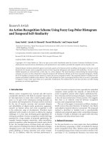
Figure 2: Elementary directivity functions, sources of degree −4
to 4.
plane a nd the loudspeakers’ radiation characteristics. Con-
sidering the synthesis of spherical harmonics of degree m and
order n, the order n is thus simply undetermined. It should
be chosen such that the P
m
n
(0) = 0(δ = π/2). This condition
is fulfilled for n
=|m| since
P
m
m
(x) = (−1)
m
(2m − 1)!
1 − x
2
m/2
. (6)
In the following, we consider that n
=|m| and refer to a
virtual source Ψ
m
of degree m. The radiation characteristics
of a subset of such elementary directivity functions, sources
of degree m, are described in Figure 2.
2.2.2. Simplification of the pressure gradient
Using far field assumption (kr
1), h
−
n
(kr) is simplified as
[10]
h
−
n
(kr)
j
n+1
e
−jkr
kr
. (7)
Similarly, the r derivative term of (5)becomes
dh
−
n
(kr)
dr
Y
mn
(φ, δ) −jk
j
n+1
e
−jkr
kr
Y
mn
(φ, δ). (8)
In the following, the term j
n+1
is omitted for simplification
of the expressions.
In the horizontal plane ( δ
= π/2), the φ derivative term
of (5) is expressed as
1
r
∂
Y
mn
∂φ
φ,
π
2
=
P
m
n
(0)
r
×
⎧
⎨
⎩
−
m sin(mφ)ifm ≥ 0,
m cos(mφ)ifm<0,
(9)
where
× denotes the multiplication operator. This term may
vanish in the far field because of the 1/r factor. However, we
will note that the zeros of Y
mn
(φ, π/2) in the r derivative term
of (5) correspond to nonzero values of the φ derivative term
(derivative of cos function is the sin function and vice versa).
Therefore, in the close field and possibly large
|m| values, the
φ derivative term may become significant in (5).
The δ derivative term of (5) is not considered here since
it simply vanishes in the loudspeaker geometry simplification
illustrated in the next section.
2.2.3. Simplification of the loudspeaker geometry
The WFS formulation is finally obtained by substituting
the secondary source distribution along column C
Υ
(x) (cf.
Figure 1) with a single secondar y source Υ
0
(x) at the inter-
section of column C
Υ
(x) and the horizontal plane. This re-
quires compensation factors that modify the associated driv-
ing functions. They are derived using the so-called stationary
phase approximation [2].
In the following, bold letters account for the discrete
time Fourier transform (DTFT) of corresponding impulse
responses. The WFS filter u
Ψ
m
(x, ω) associated to a secondary
source Υ
0
(x) for the synthesis of a virtual source Ψ
m
is de-
rived from (4)as
u
Ψ
m
(x, k) =
k
2π
g
Ψ
cos θ
0
e
−j(kr
0
−π/4)
√
r
0
Φ
m
(φ), (10)
considering low values of absolute degree
|m| and assum-
ing that the source is in the far field of the loudspeaker array
(kr
1). In this expression, ω denotes the angular frequency
and ω
= k/c where c is the speed of sound. The 0 subscript
corresponds to the value of the corresponding parameter in
the horizontal plane. θ
0
is defined such that cos θ
0
=
e
r
·
n.
Note that the δ deri vative term of (5) vanishes since
e
δ
·
n
= 0
in the horizontal plane. The φ derivative term of (5)isre-
moved for simplicity, assuming far field conditions and small
|m| values. However, we will see that this may introduce ar-
tifacts in the synthesized sound field.
g
Ψ
is a factor that compensates for the level inaccuracies
due to the simplified geometry of the loudspeaker array:
g
Ψ
=
y
R
ref
− y
L
y
R
ref
− y
Ψ
. (11)
The compensation is only effective at a reference listening
distance y
R
ref
. Outside of this line, the level of the sound field
at position r
R
can be estimated using the stationary phase ap-
proximation along the x dimension [11]. The corresponding
attenuation law Att
Ψ
m
is expressed as
Att
Ψ
m
r
R
=
y
R
ref
y
R
y
R
+
y
Ψ
m
y
R
ref
+
y
Ψ
m
1
4πd
R
Ψ
m
, (12)
assuming y
L
= 0 for simplicit y. d
R
Ψ
m
denotes the distance
between the primary source Ψ
m
and the listening position
4 EURASIP Journal on Advances in Signal Processing
r
R
. It appears as a combination of the natural attenua-
tion of the target virtual source (1/4πd
R
Ψ
m
) and of the line
array(
1/|y
R
|).
The proposed WFS filters u
Ψ
m
(x, ω) are consistent with
the expression proposed by Verheijen [7] where his frequency
dependent G(φ,0,ω) factor is substituted by the frequency
independent Φ
m
(φ) factor. The proposed expression appears
thus as a particular case of Verheijen’s formulation. However,
the frequency dependency may be reintroduced by using fre-
quency dependent weighting factors of the different elemen-
tary directivity functions Φ
m
as shown in (3). As already
noticed, the spherical harmonic based formulation however
highlights the numerous approximations necessary to derive
the WFS filters without a priori far field approximation.
The WFS filters are simply expressed as loudspeaker po-
sition and virtual source dependent gains and delays and a
general
√
ke
j(π/4)
filter. In particular, delays account for the
“shaping” of the wave front that is emitted by the loudspeaker
array.
2.3. Limitations in practical situations
In the previous part, the formulation of the WFS filters is
defined for an infinitely long continuous linear distribution of
ideal secondary sources. However, in practical situations, a
finite number of regularly spaced real loudspeakers are used.
2.3.1. Rendering artifacts
Artifacts appear, such as
(i) diffraction through the finite length aperture which
can be reduced by applying an amplitude taper [2, 3],
(ii) spatial aliasing due to the finite number of loudspeak-
ers [2, 3, 11],
(iii) near field effects for sources located in the vicinity of
the loudspeaker array for which the far field approxi-
mations used for the derivation of WFS filters (cf. (10))
are not valid [11],
(iv) degraded wave front forming since real loudspeakers
are not ideal omnidirectional point sources.
Among these points, spatial aliasing limits the sound field re-
construction of the loudspeaker arr ay above a so-called spa-
tial aliasing frequency f
al
Ψ
. Contributions of individual loud-
speaker do not fuse into a unique wave front as they do at low
frequencies [3]. Considering finite length loudspeaker arrays,
the aliasing frequency depends not only on the loudspeaker
spacing and the source location but also on the listening po-
sition [11, 12]. It can be estimated as
f
al
Ψ
r
R
=
1
max
i=1···I
Δτ
Ψ
R
(i)
, (13)
where
|Δτ
Ψ
R
(i)| is the difference between the arrival time of
the contribution of loudspeaker i and loudspeaker i +1at
listening position r
R
. The latter can be calculated from the
WFS delays of (10) and natural propagation time between
loudspeaker i and listening position r
R
.
0
2
4
6
8
10
y position (m)
−50 5
x position (m)
Far source
Loudspeakers
Close source
Microphones
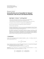
Figure 3: Test configuration, 48-channel loudspeaker array, 96 mi-
crophones at 2 m, 1 source 20 cm behind the array, 1 source 6 m
behind the array.
2.3.2. Simulations
These ar tifacts are illustrated with the test situation shown in
Figure 3. An 8 m long, 48-channel, loudspeaker array is used
for the synthesis of two virtual sources:
(1) a source of degree
−2, located at (2, 6), 6 m behind and
off-centered 2 m to the right (far source),
(2) a source of degree 2, located at (2, 0.2), 20 cm behind
and off-centered 2 m to the right (close source).
In order to characterize the emitted sound field, the response
of the loudspeaker a rray is simulated on a set of 96 omnidi-
rectional microphones positioned on a line at 2 m away from
the loudspeakers with 10 cm spacing. Loudspeakers are ideal
point sources having omnidirectional characteristics. The re-
sponse is calculated using WFS filters (see (10)) and applying
the amplitude tapper to limit diffraction [2].
Figure 3 further displays the portion of the directivity
characteristics of both sources that is synthesized on the mi-
crophones (dashed lines). It can be seen that a smaller por-
tion of the directivity characteristics of the far source, com-
pared to the close source, is synthesized on the microphones.
In the case of the far source, the right line also shows v isibil-
ity limitations of the source through the extent of the loud-
speaker array. For the far source, the few microphones lo-
cated at x>4.5 m are not anymore in the visibility area of
the source.
Figures 4(a) and 5(a) display frequency responses w
Ψ
m
(r
j
,
ω) of the loudspeaker ar ray for the synthesis of both the far
and close sources of Figure 3 on all microphone positions r
j
,
j
= 1 ···96. Figures 4(b) and 5(b) show the frequency re-
sponses of a quality function q
Ψ
m
that describes the de viation
E. Corteel 5
−40
−20
0
Level (dB)
−4
−2
0
2
4
Microphone x position (m)
10
2
10
3
10
4
Frequency (Hz)
−40 −35 −30 −25 −20 −15 −10 −50 510
Diffraction
Aliasing
(a) Frequency responses (w
Ψ
m
).
−20
0
20
Level (dB)
−4
−2
0
2
4
Microphone x position (m)
10
2
10
3
10
4
Frequency (Hz)
−20 −15 −10 −50 5101520
Diffraction
Aliasing
(b) Quality function (q
Ψ
m
).
Figure 4: Frequency responses (w
Ψ
m
) and quality function (q
Ψ
m
)
of an 8 m, 48-channel, loudspeaker array simulated on a line at 2 m
from the loudspeaker array for synthesis of a source of degree
−2
(far source of Figure 3).
of the synthesized sound field from the target. It is defined as
q
Ψ
m
r
j
, ω
=
w
Ψ
m
r
j
, ω
a
Ψ
m
r
j
, ω
, (14)
where a
Ψ
m
(r
j
, ω) is the “ideal” free-field WFS frequency re-
sponse of an infinite linear secondary source distribution at
r
j
:
a
Ψ
m
r
j
, ω
=
Att
Ψ
m
r
j
Φ
m
φ
r
j
, r
Ψ
e
−jk(|
r
j
−
r
Ψ
|)
. (15)
Att
Ψ
m
(r
j
) is the attenuation of the sound field synthesized
by an infinite linear secondary source distribution (see (12)).
Φ
m
(φ(r
j
, r
Ψ
)) corresponds to the target directivity of the
source Ψ
m
at r
j
.
For both close and far sources, the target directivity
characteristics are not reproduced above a certain frequency
which corresponds to the spatial aliasing frequency (see Fig-
ures 4 and 5). This is a fundamental limitation for the spa-
tially correct synthesis of virtual sources using WFS.
Diffraction a rtifacts are observed in Figure 4 for the syn-
thesis of the far source. They remain observable despite the
−40
−20
0
Level (dB)
−4
−2
0
2
4
Microphone x position (m)
10
2
10
3
10
4
Frequency (Hz)
−40 −35 −30 −25 −20 −15 −10 −50 510
Near field effect
Aliasing
(a) Frequency responses (w
Ψ
m
).
−20
0
20
Level (dB)
−4
−2
0
2
4
Microphone x position (m)
10
2
10
3
10
4
Frequency (Hz)
−20 −15 −10 −50 5101520
Near field effect
Aliasing
(b) Quality function (q
Ψ
m
).
Figure 5: Frequency responses (w
Ψ
m
) and quality function (q
Ψ
m
)
of an 8 m, 48-channel, loudspeaker array simulated on a line at 2 m
from the loudspeaker array for synthesis of a source of degree +2
(close source of Figure 3).
amplitude tapering [11]. They introduce small oscillations at
mid and low frequencies and limit the proper synthesis of
the null of the directivity characteristics for microphone po-
sitions around x
= 2m.
For the close source being situated at 20 cm from the
loudspeaker array, the far field approximations used for the
derivation of the WFS filters of (10) are not valid anymore.
Near-field effects can thus be observed (see Figure 5). The di-
rectivity characteristics of this source imposes the synthesis
of two nulls at x
= 0andx = 4 m which are not properly re-
produced. Moreover, the frequency responses at microphone
positions in the range x
∈ [−4, , −2] m exhibit high-pass
behavior. More generally, the synthesis of such sources com-
bines several factors that introduce synthesis inaccuracies
and limit control possibilities:
(1) the visibility angle of the source through the loud-
speaker array spans almost 180
◦
, that is, a large portion
of the directivity characteristics have to be synthesized
which is not the case for sources far from the loud-
speaker array ;
6 EURASIP Journal on Advances in Signal Processing
x(t
l
)
H(t
l
)
C( t
l
)
−
A(t
l
)
Figure 6: Equalization for sound reproduction.
(2) only few loudspeakers have significant level in the WFS
filters (cf. (10)) and may contribute to the synthesis of
the sound field.
3. EQUALIZATION TECHNIQUES FOR WAVE
FIELD SYNTHESIS
It was shown in the previous section that the synthesis of e l-
ementary directivity function using WFS exhibits reproduc-
tion artifacts even when ideal loudspeakers are used. In this
section, equalization techniques are proposed. They target
the compensation of both real loudspeaker’s radiation char-
acteristics and WFS reproduction artifacts.
Equalization has originally been employed to compen-
sate for frequency response impairments of a loudspeaker at
a given listening position. However, in the context of mul-
tichannel sound reproduction, a plurality of loudspeakers
contribute to the synthesized sound field. Listeners may be
located within an extended area where rendering artifacts
should be compensated for.
In this section, three equalization techniques are pre-
sented:
(i) individual equalization (Ind),
(ii) individual equalization with average synthesis error
compensation (AvCo),
(iii) multichannel equalization (Meq).
The first two methods enable one to compensate for the spa-
tial average deficiencies of the loudspeakers and/or WFS re-
lated impairments. The third method targets the control of
the synthesized sound field within an extended listening area.
3.1. Framework and notations
Equalization for sound reproduction is a filter design prob-
lem which is illustrated in Figure 6. x(t
l
) denotes the discrete
Figure 7: Measurement selection for individual equalization.
time (at t
l
instants) representation of the input signal. The
loudspeakers’ radiation is described by an ensemble of im-
pulse responses c
j
i
(t
l
) (impulse response of loudspeaker i
measured by microphone j). They form the matrix of signal
transmission channels C(t
l
). The matrix C(t
l
) therefore de-
fines a multi-input multi-output (MIMO) system with I in-
puts (the number of loudspeakers) and J outputs (the num-
ber of microphones).
Equalization filters h
i
(t
l
), forming the matrix H(t
l
), are
thus designed such that the error between the synthesized
sound field, represented by the convolution of signal trans-
mission channels C(t
l
)andfiltersH(t
l
), and a target, de-
scribed in A(t
l
), is minimized according to a suitable distance
function.
We restrict to the description of the free field radiation
of loudspeakers. The compensation of listening room related
artifacts is out of the scope of this article. It is considered in
the case of WFS rendering in [11, 13–16]
3.2. Individual equalization
Individual equalization (Ind) refers to a simple equalization
technique that targets only the compensation of the spatial
average frequency response of each loudspeaker. Associated
filters h
i
(t
l
) are calculated in the frequency domain as
h
i
(ω) = J ×
J
j=1
r
i
−
r
j
c
j
i
(ω)
, (16)
where
r
i
and
r
j
represent the positions of loudspeaker i and
microphone j. The individual equalization filter is thus de-
fined as the inverse of the spatial average response of the cor-
responding loudspeaker. The upper term of (16) therefore
compensates for levels differenc es due to propagation loss.
Prior to the spatial average computation, the frequency
responses c
j
i
(ω) may be smoothed. The current implemen-
tation employs a nonlinear method similar to the one pre-
sented in [16]. This method preserves peaks and compen-
sates for dips. The latter are known to be problematic in
equalization tasks.
The current implementation of individual equalization
uses only measuring j positions within a 60 degree plane an-
gle around the main axis of the loudspeaker i (cf. Figure 7).
Filters h
Ind
i
(t
l
) are designed as 800 taps long minimum phase
FIR filters at 48 kHz sampling rate.
E. Corteel 7
3.3. Individual equalization with average synthesis
error compensation
Individual equalization for wave field synthesis compensates
only for the “average” loudspeaker related impairments in-
dependently of the synthesized virtual source. However, WFS
introduces impairments in the reproduced sound field even
using ideal omnidirectional loudspeakers (see Section 2.3).
The “AvCo” (average compensation) method described here
relies on modified individual equalization filters. It targets
the compensation of the spatial average of the synthesis er-
ror, described by the quality function q
Ind
Ψ
m
of (14), while re-
producing the virtual source Ψ
m
using WFS filters of (10)
and individual equalization filters h
Ind
i
(t
l
). First, q
Ind
Ψ
m
should
be estimated for an ensemble of measuring positions j:
q
Ind
Ψ
m
(r
j
, ω) =
I
i=1
c
j
i
(ω) × h
Ind
i
(ω) × u
Ψ
m
x
i
, ω
a
Ψ
m
r
j
, ω
. (17)
Then, the modified individualization filters h
AvCo
i,Ψ
m
(ω)are
computed in the frequency domain as
h
AvCo
i,Ψ
m
(ω) =
J × h
Ind
i
(ω)
J
j
=1
q
Ind
Ψ
m
r
j
, ω
. (18)
The q
Ind
Ψ
m
(r
j
, ω)’s may also be smoothed prior to the spatial
average computation and inversion. Finally, filters h
AvCo
i,Ψ
m
(t
l
)
are desig ned as 800 taps long minimum phase FIR filters at
48 kHz sampling rate.
Contrary to individual equalization, we wil l note that the
“AvCo” equalization filters h
AvCo
i,Ψ
m
(t
l
) depend on the virtual
source Ψ
m
. However, the error compensation factor (lower
term of ( 18)) does not depend on the loudspeaker number
i. This equalization method may compensate for the spatial
average reproduction artifacts for each reproduced virtual
source. However, it may not account for position dependent
reproduction artifacts. These can be noticed for example in
Figure 5(b) for the synthesis of the close source even when
ideal omnidirectional loudspeakers are used.
3.4. Multichannel equalization
Multichannel equalization [17] consists in describing the
multichannel s ound reproduction system as a multi-input
multi-output (MIMO) system. Filters are designed so as to
minimize the error between the synthesized sound field and a
target (see Figure 6). The calculation relies on a multichannel
inversion process that is realized in the time or the frequency
domain.
Multichannel equalization, as such, controls the emitted
sound field only at a finite number of points (position of
the microphones). However, for wave field synthesis the syn-
thesized sound field should remain consistent within an ex-
tended listening area.
A WFS specific multichannel equalization technique has
been proposed in [16] and refined in [11, 18]. It targets the
compensation of the free field radiation of the loudspeaker
system. It combines a description of the loudspeaker array
radiation that remains valid within an extended listening area
together with a modified multichannel equalization scheme
that accounts for specificities of WFS [18]. The multichannel
equalization technique is only briefly presented here. For a
more complete description, the reader is referred to [18]or
[11].
It is similar to the multichannel equalization techniques
recently proposed by Spors et al. [5, 14], L
´
opez et al. [15], and
Gauthier and Berry [6] that target the compensation of the
listening room acoustics for WFS reproduction. Note that the
proposed technique was also extended to this case [11, 13, 19]
but this is out of the scope of this article.
3.4.1. MIMO system identification
The MIMO system is identified by measuring free field im-
pulse responses of each loudspeaker using a set of micro-
phones within the listening area. These are stored and ar-
ranged in a matrix C(t
l
) that describes the MIMO system.
The alternative techniques for multichannel equalization
in the context of WFS reproduction [5, 14–16]considera1-
dimensional circular microphone array [5, 14], a planar cir-
cular array [15 ], or a limited number of sensors distributed
near a reference listening position in the horizontal plane [6].
They describe the sound field within a limited area that de-
pends on the extent of the microphone array. These solutions
consider the problem of room compensation for which the
multiple reflections may emanate from any direction. Since
only linear loudspeaker arrays are used, the compensation
remains limited and suffers from both description and re-
production artifacts [11, 20].
The method considered in this article relies on a regularly
spaced linear microphone array at the height of the loud-
speakers. It can be shown that this microphone arrangement
provides a description of the main contributions to the free
field radiation of the loudspeakers in the entire horizontal
plane [11]. Note that this particular microphone arrange-
ment is also particularly adapted for linear loudspeaker ar-
rays as considered in this article.
3.4.2. Design of desired outputs
The target sound field for the synthesis of source Ψ
m
is de-
fined as the “ideal response” of the loudspeaker array for the
synthesis of source Ψ
m
. The target impulse response is de-
fined similar to (15):
A
Ψ
m
r
j
, t
=
Att
Ψ
m
r
j
Φ
m
φ
r
j
, r
Ψ
×
δ
t −
r
Ψ
− r
j
c
− τ
eq
,
(19)
where τ
eq
is an additional delay in order to ensure that the
calculated filters are causal. In the following, τ
eq
is referred
to as equalization delay and is set to 150 taps at 48 kHz sam-
pling rate. This particular value provides a tradeoff between
equalization efficiency and limitation of preringing artifacts
in the filters [18].
8 EURASIP Journal on Advances in Signal Processing
x(t
l
)
d(t
l
)
A(t
l
)
−
H
Ψ
(t
l
)
K
Ψ
(t
l
)
C( t
l
)
e(t
l
)
z(t
l
)
C
Ψ
(t
l
)
Figure 8: Block diagram of the modified inverse filtering process.
3.4.3. Multichannel inversion
Filters that minimize the mean square error may be simply
calculated in the frequency domain as
H
0,reg
=
C
∗T
C + γB
∗T
B
−1
C
∗T
A, (20)
where angular frequency ω dependencies are omitted. C
∗T
denotes the transposed and conjugate of matrix C. B is a reg-
ularization matrix and γ a regularization gain that may be
introduced to avoid ill-conditioning problems [21].
The filters H
0,reg
account for both wave front forming
and compensation of reproduction artifacts. The frequency-
based inversion process does not allow one to choose the cal-
culated filters’ length. It may also introduce pre-echos, post-
echos [22], and blocking effects [23] due to the underlying
circular convolution. The latter are due to the circularity of
Fourier transform and introduce artifacts in the calculated
filters.
A general modified multichannel inversion scheme is il-
lustrated in Figure 8 [11, 18]. We introduce a modified ma-
trix of impulse responses
C
Ψ
m
(t):
c
j
i,Ψ
m
(t) = k
i,Ψ
m
(t) ∗c
j
i
(t), (21)
where
∗ denotes the continuous time domain convolution
operator and k
i,Ψ
m
(t) is a filter that modifies the driving sig-
nals of loudspeaker i for the synthesis of source Ψ
m
accord-
ing to a given reproduction technique, for example, WFS.
This framework is similar to the one presented by L
´
opez et
al. [15]. However, in our implementation, the filters k
i,Ψ
m
only include the delays of WFS filters of (10). WFS gains are
omitted since they were found to degrade the conditioning
of the matrix
C
Ψ
m
[18].
Filters H
Ψ
m
therefore only account for the compensation
of reproduction artifacts and not for the wave front form-
ing. This modified multichannel equalization scheme is par-
ticularly interesting for WFS since the maximum delay dif-
ference considering a ten-meter long loudspeaker array may
exceed 1000 taps at 48 kHz sampling rate. This, combined
with a multichannel inversion in the time domain, enables
one to choose the filter length independently of the length
of impulse responses in
C
Ψ
m
and of the virtual source Ψ
m
.
In the following, calculated filters using multichannel equal-
ization are 800 taps long at 48 kHz. The y are preferably cal-
culated using an iterative multichannel inverse filtering algo-
rithm derived from adaptive filtering (LMS, RLS, FAP, e tc.).
The current implementation uses a multichannel version of
an MFAP algorithm [11] w hich provides a good tradeoff be-
tween convergence speed and calculation accuracy [24].
3.4.4. Above the spatial aliasing frequency
Above the WFS spatial aliasing frequency, multichannel
equalization does not provide an effective control of the
emitted sound field in an extended area [11]. The pro-
posed multichannel equalization method is therefore limited
to frequencies below the spatial aliasing frequency. Down-
sampling of
C
Ψ
m
(t
l
) is used to improve calculation speed of
the filters. Above the spatial aliasing frequency, the filters are
designed using the AvCo method presented in the previous
section [18].
3.4.5. Equalization performances
Figures 9(a) and 9(b) display the frequency responses of the
quality function q
Ψ
m
for the synthesis of the two test sources
displayed in Figure 3 using filters derived from the multi-
channel equalization method. These figures should then be
compared to, respectively, Figures 4(b) and 5(b). The quality
function is almost unchanged above the aliasing frequency.
However , diffraction and near-field artifacts are greatly re-
duced below the aliasing frequency. Remaining artifacts ap-
pear mostly at the positions of the nulls of the directional
function.
4. REPRODUCTION ACCURACY EVALUATION
In this section, the performance of the equalization tech-
niques are compared for both ideal and real loudspeakers.
Thereproductionaccuracyisestimatedforanumberofvir-
tual sources and listening positions using simple objective
criteria.
4.1. Test setup
A 48-channel linear loudspeaker array is used as a test ren-
dering setup. The array is 8 m long which corresponds to a
loudspeaker spacing of approximately 16.5 cm. Two different
types of loudspeakers are considered:
(i) ideal omnidirectional loudspeakers,
(ii) multi-actuator panel (MAP) loudspeakers (see Figure
10).
MAP loudspeakers have been recently proposed [16, 25, 26]
as an alternative to electrodynamic “cone” loudspeakers for
WFS. The large white surface of the panel vibrates through
the action of several electrodynamic actuators. Each actu-
ator works independently from the others such that one
panel is equivalent to 8 ful l-band loudspeakers. Tens to hun-
dreds of loudspeakers can be easily concealed in an existing
E. Corteel 9
−20
0
20
Level (dB)
−4
−2
0
2
4
Microphone x position (m)
10
2
10
3
10
4
Frequency (Hz)
−20 −15 −10 −50 5101520
(a) Quality function (q
Ψ
m
)forfarsourceofFigure 3.
−20
0
20
Level (dB)
−4
−2
0
2
4
Microphone x position (m)
10
2
10
3
10
4
Frequency (Hz)
−20 −15 −10 −50 5101520
(b) Quality function (q
Ψ
m
) for close source of Figure 3.
Figure 9: Frequency responses (w
Ψ
m
) and quality function (q
Ψ
m
)
of an 8 m, 48-channel, loudspeaker array simulated on a line at
2 m from the loudspeaker array for synthesis of the two sources
displayed in Figure 3. Filters are calculated using the multichannel
equalization method.
Figure 10: MAP loudspeakers.
environment given their low visual profile. However, they ex-
hibit complex directivity characteristics that have to be com-
pensated for [11, 16].
The radiation of the 48-channel MAP array has been
measured in a large room. The loudspeakers were placed
far enough (at least 3 m) from any reflecting surface so it
was possible extract their free field radiation only. The mi-
crophones were p ositioned at four different distances to the
loudspeaker array (y
=−1.5m, −2m, −3m, −4.5m, see
−4
−2
0
2
4
6
8
y position (m)
−50 5
x position (m)
1
2
3
4
5
6
7
8
9
10
11
12
13
y
=−1.5m
y
=−2m
y
=−3m
y
=−4.5m
Figure 11: Top view of the considered system: 48 regularly
spaced (16.75 cm) loudsp eakers (
∗)measuredon4depths(y =
−
1.5, −2, −3, −4.5 m) with 96 regularly spaced (10 cm) micro-
phones (circle) reproducing 13 test sources (dot).
Figure 11). On each line, impulse responses were measured
at 96 regularly spaced (10 cm) omnidirectional microphone
positions. For ideal loudspeakers, impulse responses of each
loudspeaker were estimated on virtual omnidirectional mi-
crophones at the same positions.
Equalization filters are designed according to the 3 meth-
ods. The 96 microphones situated at y
=−2m(at2mfrom
the loudspeaker array) are used to describe the MIMO sys-
tem. Therefore, the reproduction error should be minimized
along that line. However, equalization should remain effec-
tive for all other positions. A test ensemble of 13 virtual
sources (see Figure 11)ismadeof
(i) 5 “focused” sources located at 1 m (centered), 50 cm,
and 20 cm (centered and off centered) in front of the
loudspeaker array (sources 1/2/3/4/5),
(ii) 8 sources (centered and off centered) behind the loud-
speakerarrayat20cm,1m,3m,and8m(sources
6/7/8/9/10/11/12).
The chosen test ensemble represents typical WFS sources re-
produced by such a loudspeaker array. It spans possible loca-
tions of virtual sources whose visibility area cover most of the
listening space defined by the microphone arrays. In the pro-
posed ensemble, some locations correspond to limit cases for
WFS (focused sources, sources close to the loudspeaker array,
sources at the limits of the visibility area).
4.2. Reproduction accuracy criteria
The reproduction accuracy may be defined as the deviation
of the synthesized sound field compared to the target. It can
10 EURASIP Journal on Advances in Signal Processing
be expressed in terms of magnitude and time/phase response
deviation compared to a target. Both may introduce per-
ceptual artifacts such as coloration or improper localization.
They may also limit reconstruction possibilities of directivity
functions as a combination of elementary directivity func-
tions.
At a given listening position r
j
, the magnitude and the
temporal response deviation are defined as the magnitude
and the group delay extracted from the quality function
q
Ψ
m
(r
j
, ω)of(14).
The frequency sensitiv ity of the auditory system is ac-
counted for by deriving the magnitude MAG
Ψ
m
(r
j
, b) and the
group delay deviations GD
Ψ
m
(r
j
, b) in an ensemble of audi-
tory frequency bands ERB
N
(b)[27]. They are calculated as
average values of the corresponding quantities for frequen-
cies f
= ω/2π lying in [ERB
N
(b − 0.5) ···ERB
N
(b +0.5)]
where c is the speed of sound.
96 ERB
N
bands are considered covering the entire audi-
blefrequencyrange.Theevaluationishoweverlimitedfor
frequency bands between 100 Hz and the aliasing frequency
above which the directivity charac teristics cannot be synthe-
sized. Small loudspeakers have to be used for WFS because of
the relatively small spacing between the loudspeakers (typ-
ically 10–20 cm). Therefore, the lower frequency of 100 Hz
corresponds to their typical cut-off frequency. For the con-
sidered loudspeaker array, virtual source positions, and lis-
tening positions, the aliasing frequency is typically between
1000 and 2000 Hz according to (13). 30 to 40 ERB
N
bands
are thus used for the accuracy evaluation depending both on
the source and the listening position.
In the following, the reproduction accuracy is estimated
for a large number of test parameters (frequency band, lis-
tening positions, source position and degree, equalization
method). Therefore, more simple criteria should be defined.
The mean value and the standard deviation of MAG
Ψ
m
(r
j
, b)
or GD
Ψ
m
(r
j
, b) calculated for an ensemble of test parameters
areproposedassuchcriteria.
The mean value provides an estimate of the overall ob-
served deviation. Such a global deviation may typically be a
level modification (for MAG
Ψ
m
) or a time shift (for GD
Ψ
m
)
whichispossiblynotperceivedasanartfact.However,a
nonzero mean deviation for a given elementary directivity
function may introduce inaccuracies if combined with oth-
ers.
The standard deviation accounts for the variations of the
observed deviation within the ensemble of test parameters.
It can thus be seen as a better indicator of the reproduction
accuracy.
4.3. Results
The aim of this section is to compare the performances of the
three equalization methods described in Section 3 for both
ideal and MAP loudspeakers. Reproduction accuracy is esti-
mated first for the synthesis of elementary directivity func-
tions (see Figure 2).
Spherical harmonic framework enables one to synthe-
size composite directivity functions as a weighted sum of
elementary directivity functions. This reduces the dimen-
sionality of the directivity description but suppose that each
elementary func tion is perfectly synthesized or, at least, with
limited artifacts. Therefore, accuracy of composite directivity
functions is considered in Sections 4.3.2 and 4.3.3.
4.3.1. Synthesis of elementary directivity functions
Equalization filters have been calculated for all sources of the
test setup (cf. Figure 11) considering elementary directivity
functions of degree
−4 to 4. For each source position, each el-
ementary directivity function and each equalization method
MAG
Ψ
m
and GD
Ψ
m
are calculated at all microphone posi-
tions. The mean value and the standard dev iation of MAG
Ψ
m
are derived for each equalization method considering three
test parameter ensembles:
(1) al l measuring positions, all source degrees, individu-
ally for each source position (source position depen-
dency);
(2) all measuring positions, all source positions, individ-
ually for each source degree (source degree depen-
dency);
(3) all source positions, all source degrees, and all measur-
ing positions, individually for each measuring distance
to the loudspeaker array (measur ing distance depen-
dency).
Figures 12 and 13 show mean values (mean, lines) and stan-
dard deviation (std, markers) of MAG
Ψ
m
evaluated below
the aliasing frequency for the three test ensembles. They
show comparison between individual equalization (Ind), in-
dividual equalization + average synthesis error compensa-
tion (AvCo) and multichannel equalization ( Meq) for both
ideal (cf. Figure 12) and MAP (cf. Figure 13)loudspeakers.
In the case of ideal loudspeakers, no loudspeaker related im-
pairments have to be compensated for. Therefore, the filters
calculated with the individual equalization method are sim-
ple WFS filters of (10).
Similar behavior is observed for both ideal and MAP
loudspeakers. The standard deviation of MAG
Ψ
m
is gener-
ally higher for MAP loudspeakers (from 0.2 to 1 dB) than for
ideal loudspeakers. This is due to the more complex direc-
tivity characteristics of these loudspeakers that can only be
partly compensated for using the various equalization meth-
ods.
As expected, the Ind method provides the poorest results
both in terms of the mean value and the standard deviation
of MAG
Ψ
m
.TheAvCo method enables one to compensate for
the mean values inaccuracies. However, no significant im-
provements are noticed on standard deviation values. The
Meq method performs best having mean values remaining
between
−0.5 and 0.5 dB and a standard deviation at least
1 dB lower than other methods for all situations. These are
significant differences that may lead to audible changes (re-
duced coloration, increased precision for manipulation of
source directivity characteristics, etc.).
Sources close the loudspeaker array (4/5/6/7) have worst
results. This is coherent with the general comments on this
E. Corteel 11
−8
−6
−4
−2
0
2
4
6
8
Magnitude deviation value (dB)
12345678910111213
Source number
Ind., mean
AvCo., mean
Meq., mean
Ind., std.
AvCo., std.
Meq., std.
(a) Source position dependency.
−8
−6
−4
−2
0
2
4
6
8
Magnitude deviation value (dB)
−4 −3 −2 −10 1 2 3 4
Source deg ree
Ind., mean
AvCo., mean
Meq., mean
Ind., std.
AvCo., std.
Meq., std.
(b) Source degree dependency.
−8
−6
−4
−2
0
2
4
6
8
Magnitude deviation value (dB)
−4.5 −3 −2 −1.5
y measuring position (m)
Ind., mean
AvCo., mean
Meq., mean
Ind., std.
AvCo., std.
Meq., std.
(c) Measuring distance dependency.
Figure 12: Mean value (mean) and standard deviation (std) of
MAG
Ψ
m
evaluated below the aliasing frequency for all m icrophone
and source positions. Comparison between individual equalization
(Ind), individual equalization + average synthesis error compensa-
tion (AvCo), and multichannel equalization (Meq) for ideal loud-
speakers.
−8
−6
−4
−2
0
2
4
6
8
Magnitude deviation value (dB)
12345678910111213
Source number
Ind., mean
AvCo., mean
Meq., mean
Ind., std.
AvCo., std.
Meq., std.
(a) Source position dependency.
−8
−6
−4
−2
0
2
4
6
8
Magnitude deviation value (dB)
−4 −3 −2 −10 1 2 3 4
Source deg ree
Ind., mean
AvCo., mean
Meq., mean
Ind., std.
AvCo., std.
Meq., std.
(b) Source degree dependency.
−8
−6
−4
−2
0
2
4
6
8
Magnitude deviation value (dB)
−4.5 −3 −2 −1.5
y measuring position (m)
Ind., mean
AvCo., mean
Meq., mean
Ind., std
AvCo., std
Meq., std
(c) Measuring distance dependency.
Figure 13: Mean value (mean) and standard deviation (std) of
MAG
Ψ
m
evaluated below the aliasing frequency for all m icrophone
and source positions. Comparison between individual equalization
(Ind), individual equalization + average synthesis error compensa-
tion (AvCo), and multichannel equalization (Meq) for MAP loud-
speakers.
12 EURASIP Journal on Advances in Signal Processing
Table 1: Mean value and standard deviation GD
ERB
for all micro-
phone positions, all source positions and degrees.
Ideal MAP
Mean Std Mean Std
Ind −0.02 ms 1.27 ms 1.39 ms 1.70 ms
AvCo
0.05 ms 1.27 ms 1.36 ms 1.67 ms
Meq
0.09 ms 1.23 ms 0.90 ms 1.39 ms
1234
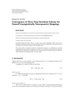
Figure 14: Rotated elementary directivity functions.
type of sources made in Section 2.3.However,AvCo and par-
ticularly Meq methods enables to limit the standard deviation
of MAG
Ψ
m
to similar values than other sources (see Figures
12(a) and 13(a)).
The reproduction accuracy (standard deviation of
MAG
Ψ
m
) is best for omnidirectional sources and degrades
with the absolute value of the source degree (see Figures
12(b) and 13(b)). This means that the more complex the di-
rectivity characteristics are, the lower is the accuracy.
The accuracy is independent of listening distance (see
Figures 12(c) and 13(c)). This is the case even for the Meq
method even if filters are calculated to minimize the repro-
duction error for y
=−2monly.
For GD
Ψ
m
, the mean value and the standard deviation
are only given for each equalization method considering all
measuring positions, all source positions, and all source de-
grees. They are shown for both ideal and MAP loudspeakers
in Table 1. Only small differences are observed between the
various equalization methods. Only for MAP loudspeakers,
the Meq method performs slightly better but does not com-
pensate for all reproduction artifacts.
As for MAG
Ψ
m
, source position dependency, source de-
gree dependency, and measuring distance dependency anal-
ysis were performed but are not shown here. They exhibit
similar, but less pronounced, tendencies concerning tem-
poralreproductionaccuracythanforMAG
Ψ
m
.Accuracyis
worst for close sources to the array and for high absolute
source degrees. However, the standard deviation never ex-
ceeds 2 milliseconds which is below the audible threshold for
coloration artifacts [28] even for sensible conditions (ane-
choic conditions, transient signal).
4.3.2. Rotated elementary directivity functions
In this section, the directivity characteristics under study may
be expressed as cos(m(φ
− π/4m)). They are obtained by
rotating the elementary directivity function of degree m at
an intermediate position between degree
−m and degree m
(see Figures 2 and 14). In the following, they are referred
to as rotated elementary directivity functions of degree m.
−8
−6
−4
−2
0
2
4
6
8
Magnitude deviation value (dB)
1234
Source deg ree
Direct, mean
Comp., mean
Direct, std.
Comp., std.
(a) Ideal loudspeakers.
−8
−6
−4
−2
0
2
4
6
8
Magnitude deviation value (dB)
1234
Source deg ree
Direct, mean
Comp., mean
Direct, std.
Comp., std.
(b) Map loudspeakers.
Figure 15: Mean value and standard deviation of MAG
Ψ
m
evalu-
ated below the aliasing frequency for all microphone and source
positions. Synthesis of rotated elementary directivity function (see
(22)). Comparison between recomposition from elementary direc-
tivity (comp) and direct synthesis (direct). All filters are calculated
using individual equalization + average synthesis error compensa-
tion (AvCo).
Trigonometrical identities enable to express them as a combi-
nation of elementary directivity functions of degree
−m and
m:
cos
m
φ −
π
4m
=
1
√
2
cos(mφ)+sin(mφ)
. (22)
These characteristics can thus be synthesized using whether
a direct synthesis specifying the required radiation charac-
teristics as the target sound field, either by combining filters
obtained for the same source position for degree
−m and m.
Figures 15 and 16 show mean values and standard de-
viation of MAG
Ψ
m
comparing direct synthesis (direct) and
composition (comp) of filters calculated for degree
−m and
m. Results are given for each degree of rotated elemen-
tary directivity function for both ideal loudspeakers (Figures
15(a) and 16(a)) and MAP loudspeakers (Figures 15(b) and
E. Corteel 13
−8
−6
−4
−2
0
2
4
6
8
Magnitude deviation value (dB)
1234
Source deg ree
Direct, mean
Comp., mean
Direct, std.
Comp., std.
(a) Ideal loudspeakers.
−8
−6
−4
−2
0
2
4
6
8
Magnitude deviation value (dB)
1234
Source deg ree
Direct, mean
Comp., mean
Direct, std.
Comp., std.
(b) Map loudspeakers.
Figure 16: Mean value and standard deviation of MAG
Ψ
m
evalu-
ated below the aliasing frequency for all microphone and source
positions. Synthesis of rotated elementary directivity function (see
(22)). Comparison between recomposition from elementary direc-
tivity (comp) and direct synthesis (direct). All filters are calculated
using multichannel equalization (Meq).
16(b)) considering all source and microphone positions. In
Figure 15, all filters are calculated using the AvCo method.
Figure 16 displays results for filters calculated using the Meq
method. For b oth equalization methods, “direct” or “comp”
synthesis of rotated elementary directivity functions exhibit
similar tendencies with respect to degree m. As in the case of
elementary directivity functions, the accuracy generally de-
grades with increasing degrees.
The Meq method performs better than the AvCo method.
Using the Meq method, the “direct” or the “comp” synthesis
perform very similar. The difference between mean values or
between standard deviations is less than 0.2 dB for all situ-
ations (see Figure 16). For the AvCo method, this difference
can be as large as 1.5 dB (mean values of MAG
Ψ
m
for degree
2, see Figure 15(a)). This mean value deviation may be prob-
lematic while combining these rotated elementary directivity
1234
Figure 17: “Combined” directivities.
functions with another elementary directivity function as
proposed in the next section.
4.3.3. Combined directivities
The reproduction accuracy is estimated for another type of
composite directivity, referred to as “combined” directivity,
which is defined as a combination of rotated elementary di-
rectivity functions and the elementary directivity function of
degree 0 (omni):
Φ
m
(φ) =
0.5
√
2
cos(mφ)+sin(mφ)
+0.5. (23)
The characteristics of the “combined” directivities of de-
grees 1 to 4 are displayed in Figure 17. Considering visibility
criteria of the test source positions (cf. Figure 11), only the
lower quarter or the lower half of the directivity figure is syn-
thesized within the listening area. Therefore, the synthesized
directivity figure is a beam which becomes sharper with in-
creasing degree.
The test situations are the same as for rotated elemen-
tary directivity functions. Accuracy results are displayed in
Figures 18 and 19. The synthesized sound field for the re-
production of these “combined” directivities exhibits large
inaccuracies w hen using the AvCo method. The errors are
particularly large for direct synthesis of “combined” directiv-
ities of degrees 3 and 4. The standard deviation of MAG
Ψ
m
is
even out of bounds (> 8 dB) considering both ideal and MAP
loudspeakers for sources of degree 4. The “comp” synthesis
exhibits lower standard deviation of MAG
Ψ
m
but high mean
values (
≈ 6dB).TheMeq method limits the reproduction er-
ror . The difference between direct and composition is below
0.5 dB considering mean values of MAG
Ψ
m
. This difference
increases to 1 dB for the standard deviation of MAG
Ψ
m
.
4.4. Discussion and real-time rendering
In this section, three different equalization methods were
used in order to compensate for rendering deficiencies while
synthesizing directional virtual sources using WFS. It could
be seen that the more complex techniques (Meq and AvCo)
are also the more efficient ones and that efficiency increases
with complexity.
The equalization process can be regarded as an advanced
calibration procedure that has to be done once for a given
system. The Meq and AvCo methods require to estimate (and
invert) the free field loudspeaker response at an ensemble of
listening position for each and every source position and di-
rectivity function. This can appear as a cumbersome task.
14 EURASIP Journal on Advances in Signal Processing
−8
−6
−4
−2
0
2
4
6
8
Magnitude deviation value (dB)
1234
Source deg ree
Direct, mean
Comp., mean
Direct, std.
Comp., std.
(a) Ideal loudspeakers.
−8
−6
−4
−2
0
2
4
6
8
Magnitude deviation value (dB)
1234
Source deg ree
Direct, mean
Comp., mean
Direct, std.
Comp., std.
(b) Map loudspeakers.
Figure 18: Mean value and standard deviation of MAG
Ψ
m
evalu-
ated below the aliasing frequency for all microphone and source
positions. Synthesis of “combined” directivity (cf. (23)). Compar-
ison between recomposition from elementary directivity (comp)
and direct synthesis (direct). All filters are calculated using individ-
ual equalization + average synthesis error compensation (AvCo).
However, one should take into account the limited localiza-
tion resolution of the human auditory system [29]inor-
der to define a finite size database of source positions for a
given setup [11, 18]. For the system described in Section 4.1,
about six hundred source positions should be considered.
The spherical harmonic representation enables one to re-
strict the “infinite” directivity space to a finite number of ele-
ments. The current implementation considers elementary di-
rectivity functions of degree
−2 to 2. Therefore, about three
thousand filters should be calculated per loudspeaker and
stored in a database. For the Meq method, this takes about
fifty hours on a modern PC having two 2 GHz dual core pro-
cessors on a not fully optimized code under Matlab
TM
.The
AvCo method is “only” five to six times more efficient since
for all sources the loudspeaker array response has to be com-
puted and smoothed on numerous microphone positions.
The Ind method has much lower complexity since only one
−8
−6
−4
−2
0
2
4
6
8
Magnitude deviation value (dB)
1234
Source deg ree
Direct, mean
Comp., mean
Direct, std.
Comp., std.
(a) Ideal loudspeakers.
−8
−6
−4
−2
0
2
4
6
8
Magnitude deviation value (dB)
1234
Source deg ree
Direct, mean
Comp., mean
Direct, std.
Comp., std.
(b) Map loudspeakers.
Figure 19: Mean value and standard deviation of MAG
Ψ
m
evalu-
ated below the aliasing frequency for all microphone and source
positions. Synthesis of “combined” directivity (cf. (23)). Compar-
ison between recomposition from elementary directivity (recomp)
and direct synthesis (direct). All filters are calculated using multi-
channel equalization (Meq).
filter per loudspeaker has to be computed for all sources. It is
also, by far, the least effective.
The three methods provide filters of same sizes (800 taps
at 48 kHz in the current implementation) together with an
ensemble of delays for each loudspeaker and each considered
virtual source. Therefore, the real-time processing load is the
same for both the Meq and AvCo methods. It is only lower for
the Ind since the filters do not depend on the virtual source
characteristics.
Figure 20 presents the architecture of a typical WFS ren-
dering system. The complete system has a network s truc-
ture. Rendering modules are associated with a group of
loudspeakers. They get audio streams and “scene descrip-
tion parameters” as an input from a communication network
[30]. The scene-description parameters contain data describ-
ing, for each source, its position and directivity characteris-
tics. Each of the rendering modules has its own database of
E. Corteel 15
Scene description parameters
WFS sources
Input signals
WFS rendering WFS rendering
Positions/
directivity
of WFS
sources
Filters
database
1
2
M
Source 1
Source 2
Source M
Figure 20: WFS system rendering architecture.
Listening area
Source directivity
Visible portion
of directivity
characteristics
Figure 21: M3S directivity interface.
pre-calculated filters for the ensemble of loudspeakers it is
attached to. The current implementation of WFS rendering
supports real-time synthesis and manipulation of directional
sources as a weighted sum of elementary directivity functions
from degree
−2 to degree 2. For a more intuitive manipula-
tion, elementary directivit y functions are grouped by same
“absolute degree” (0: omni,
−1/1: dipole, −2/2: quadripole).
For each absolute degree, a level and an orientation parame-
ter are defined. They enable one to synthesize both elemen-
tary directivity functions and directivity combinations using
basic trigonometrical identities.
A directivity manipulation and visualization interface
is presented in Figure 21. For each virtual source, source
position and directivity parameters are manipulated and
transmitted to the communication network [30]. A visual
representation of the synthesized directivity is displayed for
each absolute degree next to the manipulated parameters.
The interface also displays the composite directivity together
with the visibility angle of the source through the loud-
speaker array. The latter describes the visible portion of the
directivity characteristics within the listening area. This is
further displayed on a global view which represents the at-
tenuation factor due to the synthesized directivity depending
on the listening position.
The proposed interface remains limited to the visualiza-
tion of directivity for a unique source. More advanced inter-
faces may be used combining a visualization of the spatial or-
ganization of the sound scene (position of sources) together
with directivity information. For example, a representation
of the source directivity may be displayed in the background
of the interface as proposed by Delerue [31].
5. APPLICATIONS OF DIRECTIONAL SOURCES FOR
WAVE FIELD SYNTHESIS
In this section, applications of directional sources for WFS
are discussed. They concern direct sound manipulation and
interaction with the listening environment.
5.1. Direct sound manipulation
As a holophonic sound reproduction technique, WFS targets
the synthesis of the physical characteristics of sound fields
within an extended listening area. Contrary to sweet-spot-
based techniques (stereo, 5.1, first-order ambisonics), the lis-
tener may experience natural variations in perception of the
various sound sources while wander in the WFS installation.
The localization may vary according to the relative position
of listener and the sound sources (parallax effect) indepen-
dently of the loudspeakers’ position [32]. Natural modifi-
cation of level or sound color can be perceived. The virtual
environment therefore provides coherent proprioceptive and
auditory cues to the listener which increase the sensation of
presence [33].
Directivity can be used as a tool to create or increase dis-
parities within the listening area. Sound sources are given a
directional radiation pattern such that they are heard prefer-
ably in a portion of the listening area. In the context of sound
installations [34], “unnatural” sound sources may be created.
For example, a “two-mouth head” may be synthesized using
a source of degree
−2 which creates a zero in front and lobes
to the sides. More realistic approaches could be envisaged
such as an attempt of “spatial additive synthesis” [35]where
the output of the different vibration modes of an instrument
to be reproduced or synthesized would be coupled with cor-
responding directional sources. An approach to record and
reproduce sound source directivity has also been presented
by Jacques et al. [36]. It is based on multimicrophone record-
ings that are mapped to directional sources reproduced on a
WFS setup.
These approaches are bound to the limitations of the
synthesis of directional sources using WFS (horizontal di-
rectivity dependency only, reduced visibility, below the
16 EURASIP Journal on Advances in Signal Processing
aliasing frequency). However, informal listening sessions
could demonstrate the benefit of the reproduction of direc-
tive sources. More studies are required to evaluate the per-
ceptual effect of these inaccuracies.
5.2. Interaction with listening environment
Recent studies have described the interaction of a linear WFS
array with the listening environment [11, 37–39]. Below the
aliasing frequency, the loudspeaker array may be regarded
as an aperture through which the sound field of the tar-
get source propagates. Considering the horizontal plane, the
loudspeaker array radiates sound energy mostly within the
visibility area of the source through the loudspeaker array
[11, 38]. Outside of the horizontal plane, the emitted sound
field manifests a symmetry around the axis of the loud-
speaker array.
The total acoustic power emitted by the array is depen-
dent both on source position and source directivity, more ex-
actly on the portion of the source directivity which is v isible
through the loudspeaker ar ray [38]. The level of the rever-
berant field is proportional to the total acoustic power emit-
ted by the array. Therefore, directivity may be used to partly
control the level of natural reverberated field within the en-
vironment.
In [39], Caulkins et al. describe measurements of a WFS
array in a concert hall using a high spatial resolution micro-
phone [40]. These measurements provide a spatiotemporal
description of the early room effect. It is shown that direc-
tional sources can be used to create lateral reflections while
eliminating the direct sound at the position of the micro-
phone. This is achieved by synthesizing sources that present a
zero at listening positions and have lobes that illuminate side
walls. Alternatively, a directivity beam can be created in order
to emit sound energy preferably in the direction of the listen-
ing area while limiting the energy radiated to the sides [39].
Directivity can thus be used to manipulate the early room ef-
fect which is related to perceptual attr ibutes such as apparent
source width or room envelopment.
A similar effect can be obtained using a 3D array of loud-
speakers (“la Tim
´
ee”) and is described in [41]. This device
enables the synthesis of directivity over the entire solid angle
as a combination of a monopole and 3 orthogonal dipoles.
Unlike WFS, directional sources can only be synthesized at
the position of this directivity controllable loudspeaker.
6. CONCLUSION
The synthesis of directional sound sources using WFS was
presented in this article. The proposed formulation relies on
the synthesis of elementary directivity functions based on a
subset of spherical harmonics. This versatile representation
allows for manipulations of directivity characteristics as a
weighted sum of elementary directivity functions.
Limitations are however to be expected while synthesiz-
ing directive characteristics for virtual sources. Only hor-
izontal dep endencies in directivity characteristics can be
reproduced. Because of the finite length of the loudspeaker
array, synthesis is only possible within a visibilit y window.
The finite number of loudspeakers also restricts the proper
reconstruction of wave fronts below the so-called aliasing fre-
quency. Apart from these spatial and frequency related limi-
tations, the limited validity of the proposed approximations
to derive WFS introduces artifacts even when ideal omnidi-
rectional loudspeakers are used.
Equalization techniques should be used to reduce these
artifacts and to compensate for the radiation characteris-
tics of real loudspeakers. An extensive study on reproduc-
tion accuracy of elementary directivity functions and com-
posite directivity figures was performed to compare the per-
formance of three equalization techniques for both ideal and
real loudspeakers. It was shown that the proposed multichan-
nel equalization technique enables to reduce reproduction
artifacts within an extended listening area. Moreover, this
method ensures that composite directivities are properly syn-
thesized as a weighted sum of elementary directivity func-
tions. It thus allows real-time manipulations of directivity
characteristics with limited reconstruction errors below the
spatial aliasing frequency.
Applications of directional sources for WFS were finally
discussed in the context of virtual or augmented environ-
ments. Directivity allows one to model and reproduce nat-
ural or unnatural disparities of the sound scene within an
extended listening area. It also provides control parameters
for adjusting the interaction of the loudspeaker array with
the listening environment (early room effect, level of rever-
berant field).
ACKNOWLEDGMENTS
The author would like to thank Olivier Warusfel and Terence
Caulkins for fruitful comments and discussions on the topic.
Thanks a lot to the anonymous reviewers for helpful com-
ments on the initial manuscript.
REFERENCES
[1] A. J. Berkhout, D. de Vries, and P. Vogel, “Acoustic control by
wave field synthesis,” Journal of the Acoustical Society of Amer-
ica, vol. 93, no. 5, pp. 2764–2778, 1993.
[2] E. W. Start, Direct sound enhancement by wave field synthesis,
Ph.D. thesis, Delft University of Technology, Delft, Pays Bas,
The Netherlands, 1997.
[3] R. Nicol, Restitution sonore spatialis
´
ee sur une zone
´
etendue: ap-
plication
`
alat
´
el
´
epr
´
esence, Ph.D. thesis, Universit
´
e du Maine, Le
Mans, France, 1999, />RozennNicol
PhD.html.
[4] O. Warusfel, E. Corteel, N. Misdariis, and T. Caulkins, “Re-
production of sound source directivity for future audio appli-
cations,” in Proceedings of the 18th International Congress on
Acoustics (ICA ’04), Kyoto, Japan, April 2004.
[5]S.Spors,A.Kuntz,andR.Rabenstein,“Anapproachtolis-
tening room compensation with wave field synthesis,” in Pro-
ceedings of the 24th Convention of the Audio Engineer ing Society
(AES ’03), pp. 70–82, Banff, Canada, June 2003.
E. Corteel 17
[6] P A. Gauthier and A. Berry, “Adaptive wave field synthesis
with independent ra diation mode control for active sound
field reproduction: theory,” Journal of the Acoustical Soc i ety of
America, vol. 119, no. 5, pp. 2721–2737, 2006.
[7] E.N.G.Verheijen,Sound reproduction by wave field synthesis,
Ph.D. thesis, Delft University of Technology, Delft, Pays Bas,
The Netherlands, 1997.
[8]E.G.Williams,Fourier Acoustics: Sound Radiation and
Nearfield Acoustical Holography, Academic Press, San Diego,
Calif, USA, 1999.
[9] A. J. Berkhout, Applied Seismic Wave Theory, Elsevier, Amster-
dam, The Netherlands, 1987.
[10] M. Abramovitz and I. A. Stegun, Handbook of Mathematical
Functions, Dover, New York, NY, USA, 9th edition, 1970.
[11] E. Corteel, Caract
´
erisat ion et Extensions de la Wave Field Syn-
thesis en conditions r
´
eelles d’
´
ecoute, Ph.D. thesis, Universit
´
e
de Paris VI, Paris, France, 2004, />articles/textes/Corteel04a/.
[12] E. Corteel, “On the use of irregularly spaced loudspeaker ar-
rays for wave field s ynthesis, potential impact on spatial alias-
ing frequency,” in Proceedings of the 9th International Confer-
ence on Digital Audio Effects (DAFx ’06), pp. 209–214, Mon-
treal, Quebec, Canada, September 2006.
[13] E. Corteel and R. Nicol, “Listening room compensation for
wave field synthesis. What can be done?” in Proceedings of the
23th Convention of the Audio Engineering Society (AES ’03),
Helsingør, Danemark, June 2003.
[14] S. Spors, H. Buchner, and R. Rabenstein, “Adaptive listening
room compensation for spatial audio systems,” in Proceed-
ings of the 12th European Signal Processing Conference (EU-
SIPCO ’04), Vienna, Austria, September 2004.
[15] J. J. L
´
opez, A. Gonz
´
alez, and L. Fuster, “Room compensation
in wave field synthesis by means of multichannel inversion,” in
Proceedings of IEEE Workshop on Applications of Signal Process-
ing to Audio and Acoustics (WASPAA ’05), pp. 146–149, New
Paltz, NY, USA, October 2005.
[16] E. Corteel, U. Horbach, and R. S. Pellegrini, “Multichannel in-
verse filtering of multiexciter distributed mode loudspeaker
for wave field synthesis,” in Proceedings of the 112th Conven-
tion of the Audio Engineering Society (AES ’02), Munich, Alle-
magne, Germany, May 2002.
[17] P. A. Nelson, F. Ordu
˜
na-Bustamante, and H. Hamada, “Mul-
tichannel signal processing techniques in the reproduction of
sound,” Journal of the Audio Engineering Society, vol. 44, no. 11,
pp. 973–989, 1996.
[18] E. Corteel, “Equalization in extended area using multichannel
inversion and wave field synthesis,” Journal of the Audio Engi-
neering Society, vol. 54, no. 12, 2006.
[19] R.vanZon,E.Corteel,D.deVries,andO.Warusfel,“Multi-
actuator panel (map) loudspeakers: how to compensate for
their mutual reflections?” in Proceedings of the 116th Conven-
tion of the Audio Engineering Society (AES ’04), Berlin, Alle-
magne, Germany, March 2004.
[20] S. Spors, M. Renk, and R. Rabenstein, “Limiting effects of ac-
tive room compensation using wave field synthesis,” in Pro-
ceedings of the 118th Convention of the Audio Engineering Soci-
ety (AES ’05), Barcelona, Spain, May 2005.
[21] O. Kirkeby, P. A. Nelson, H. Hamada, and F. Ordu
˜
na-
Bustamante, “Fast deconvolution of multichannel systems us-
ing regularization,” IEEE Transactions on Speech and Audio
Processing, vol. 6, no. 2, pp. 189–194, 1998.
[22] M. Guillaume, Y. Grenier, and G. Richard, “Iterative algo-
rithms for multichannel equalization in sound reproduction
systems,” in Proceedings of IEEE International Conference on
Acoustics, Speech and Signal Processing (ICASSP ’05), vol. 3, pp.
269–272, Philadelphia, Pa, USA, March 2005.
[23] S. G. Norcross, G. A. Soulodre, and M. C. Lavoie, “Subjective
investigations of inverse filtering,” Journal of the Audio Engi-
neering Society, vol. 52, no. 10, pp. 1003–1028, 2004.
[24] M. Bouchard, “Multichannel affine and fast affine projection
algorithms for active noise control and acoustic equalization
systems,” IEEE Transactions on Speech and Audio Processing,
vol. 11, no. 1, pp. 54–60, 2003.
[25] M. M. Boone and W. P. J. de Bruijn, “On the applicability of
distributed mode loudspeakers panels for wave field synthesis
sound reproduction,” in Proceedings of the 108th Convention of
the Audio Engineering Society (AES ’00), Paris, France, Febru-
ary 2000.
[26] M. M. Boone, “Multi-actuator panels (maps) as loudspeaker
arrays for wave field synthesis,” Journal of the Audio Engineer-
ing Society, vol. 52, no. 7-8, pp. 712–723, 2004.
[27] M. Slaney, “An efficient implementation of the patterson-
holdsworth filter bank,” Tech. Rep. 35, Apple Computer, Cu-
pertino, Calif, USA, 1993.
[28] S. Flanagan, B. C. J. Moore, and M. A. Stone, “Discrimination
of group delay in clicklike signals presented via headphones
and loudspeakers,” Journal of the Audio Engineering Society,
vol. 53, no. 7-8, pp. 593–611, 2005.
[29] J. Blauert, Spatial Hearing, The Psychophysics of Human Sound
Localization, MIT Press, Cambridge, Mass, USA, 1999.
[30] R. Pellegrini, M. Rosenthal, and C. Kuhn, “Wave field synthe-
sis: open system architecture using distributed processing,” in
Forum Acusticum, Budapest, Hungary, September 2005.
[31] O. Delerue, “Visualization of perceptual parameters in inter-
active user interfaces: application to the control of sound spa-
tialization,” in Proceedings of the 120th Convention of Audio En-
gineering Society (AES ’06), Paris, France, May 2006.
[32] M. Nogu
`
es, E. Corteel, and O. Warusfel, “Monitoring distance
effect with wave field synthesis,” in Proceedings of the 6th Inter-
national Conference on Digital Audio Effects (DAFx ’03),Lon-
don, UK, September 2003.
[33] O. Warusfel and I. Viaud-Delmon, “Contribution of interac-
tive 3D sound to presence,” in Proceedings of the 6th Inter-
national Workshop on Presence, Aalborg, Danemark, October
2003.
[34] G. Grand, E. Corteel, and R. Kronenber, “L’amiral cherche une
maison
`
a louer,” Sound installation, Centre Georges Pompi-
dou, DADA exhibition, October 2005–January 2006, 2005.
[35] O. Warusfel, N. Misdariis, T. Caulkins, and E. Corteel, “Radia-
tion control applied to sound synthesis: an attempt for “spatial
additive synthesis”,” in Proceedings of the 147th Meeting of the
Acoustical Society of America (ASA ’04),NewYork,NY,USA,
May 2004.
[36] R.Jacques,B.Albrecht,F.Melchior,andD.deVries,“Anap-
proach for multichannel recording and reproduction of sound
source directivit y,” in Proceedings of the 119th Convention of the
Audio Engineering Society (AES ’05)
,NewYork,NY,USA,Oc-
tober 2005.
[37] T. Caulkins, E. Corteel, and O. Warusfel, “Wave field synthesis
interaction with the listening environment, improvements in
the reproduction of virtual sources located inside the listen-
ing room,” in Proceedings of the 6th International Conference
on Digital Audio Effects (DAFx ’03),London,UK,September
2003.
[38] T. Caulkins and O. Warusfel, “Characterization of the rever-
berant sound field emitted by a wave field synthesis driven
loudspeaker array,” in Proceedings of the 120th Convention of
18 EURASIP Journal on Advances in Signal Processing
the Audio Engineering Society (AES ’06), Paris, France, May
2006.
[39] T.Caulkins,A.Laborie,E.Corteel,R.Bruno,S.Montoya,and
O. Warusfel, “Use of a high spatial resolution microphone to
characterize the early reflections generated by a WFS loud-
speaker array,” in Proceedings of the 28th Convention of the Au-
dio Engineering Society (AES ’06), Pitea, Sweden, June 2006.
[40] A. Laborie, R. Bruno, and S. Montoya, “A new comprehensive
approach of surround sound recording,” in Proceedings of the
114th Convention of the Audio Engineering Society (AES ’03),
Amsterdam, Pays Bas, The Netherlands, March 2003.
[41] O. Warusfel and N. Misdariis, “Directivity synthesis with a 3D
array of loudspeakers, application for stage performance,” in
Proceedings of the International Conference on Digital Audio Ef-
fects (DAFx ’01), Limerick, Ireland, December 2001.
E. Corteel was born in Vernon, France,
in 1978. He received an M.Sc. degree
in telecommunication engineering in 2000
and a Ph.D. degree in acoustics and signal
processing from Paris 6 University, Paris,
France, in 2004. He joined Studer Profes-
sional Audio AG in 2001 where he started to
work on wave field synthesis in the context
of the European Carrouso IST project no.
1999-20993. He followed up this research at
IRCAM, Paris, France, between 2002 and 2004. Since 2005, he has
shared his time between IRCAM and Sonic Emotion, Oberglatt,
Switzerland. His research interests include the design and evalua-
tion of spatial sound rendering techniques for virtual or augmented
reality applications (sound installations, concerts, simulation envi-
ronments, etc.), as well as spatial hearing and crossmodal interac-
tions.