Báo cáo hóa học: " An Approach to Optimum Joint Beamforming Design in a MIMO-OFDM Multiuser System" potx
Bạn đang xem bản rút gọn của tài liệu. Xem và tải ngay bản đầy đủ của tài liệu tại đây (440.04 KB, 12 trang )
EURASIP Journal on Wireless Communications and Networking 2004:2, 210–221
c
2004 Hindawi Publishing Corporation
An Approach to Optimum Joint Beamforming Design
in a MIMO-OFDM Multiuser System
Antonio Pascual-Iserte
Department of Signal Theory and Communications, Technical University of Catalonia (UPC), 08034 Barcelona, Spain
Email:
Ana I. P
´
erez-Neira
Department of Signal Theory and Communications, Technical University of Catalonia (UPC), 08034 Barcelona, Spain
Email:
Telecommunications Technological Center of Catalonia (CTTC), 08034 Barcelona, Spain
Miguel
´
Angel Lagunas
Department of Signal Theory and Communications, Technical University of Catalonia (UPC), 08034 Barcelona, Spain
Telecommunications Technological Center of Catalonia (CTTC), 08034 Barcelona, Spain
Email:
Received 28 November 2003; Revised 1 April 2004
This paper describes a multiuser scenario with several terminals acceding simultaneously to the same frequency channel. The ob-
jective is to design an optimal multiuser system that may be used as a comparative framework when evaluating other suboptimal
solutions and to contribute to the already published works on this topic. The present work assumes that a centralized manager
knows perfectly all the channel responses between all the terminals. According to this, the transmitters and receivers, using an-
tenna arrays and leading to the so-called multiple-input-multiple-output (MIMO) channels, are designed in a joint beamforming
approach, attempting to minimize the total transmit power subject to quality of service (QoS) constraints. Since this optimization
problem is not convex, the use of the simulated annealing (SA) technique is proposed to find the optimum solution.
Keywords and phrases: multiuser systems, simulated annealing, antenna arrays, MIMO systems, orthogonal frequency division
multiplexing, joint beamforming.
1. INTRODUCTION
One of the most important problems of the current and com-
mercial wireless communication systems is that the number
of users and the quality of service (QoS) are very limited, in-
cluding the bit-rate and the bit error rate (BER). These limi-
tations are extremely important since the demands for wire-
less services are increasing at a very high speed. In this sce-
nario, diversity is a powerful method to increase the number
of users and improve the performance. Among the different
solutions, the spatial diversity, based on the use of multiple
antennas at the transmitter and/or the receiver, has received
much attention in last years. Thanks to such techniques, the
performance and capabilities of the communication systems
can approach the theoretical limits of the wireless channel.
As an illustrative example, we may cite the space division
multiple access (SDMA), an advanced medium access pro-
tocol that permits the increase of the number of users that
can be served simultaneously. In these scenarios, the signals
from different users can be separated using array and multi-
channel processing techniques. Thus, spatial processing can
be adopted as a very powerful tool in the so-called multiuser
systems. Although currently there are several papers related
to this topic, f urther work is necessary on this research area
to fully exploit the capabilities and benefits provided by the
use of multiple antennas in multiuser scenarios.
In this paper, a multiuser wireless scenario is considered
in which all the “terminals” are assumed to have multiple an-
tennas and, as a consequence, several parallel multiple-input-
multiple-output (MIMO) channels arise. In the case of a cel-
lular system, the terminals correspond to both the mobile
terminals (MTs) and base stations (BSs). It is also assumed
that all of them accede simultaneously to the same frequency
radio channel. In this kind of MIMO systems, and depend-
ing on the quality and quantit y of the channel state infor-
mation (CSI) at the transmitters, several designs and archi-
tectures are possible. We are interested in designing an op-
timum SDMA strategy that can be used as a comparative
Joint Beamforming Design in a MIMO-OFDM Multiuser System 211
framework when designing and evaluating other suboptimal
designs for multiuser MIMO systems. According to this ob-
jective, we consider that there exists a centralized manager
with knowledge of the channel responses between all the ter-
minals in the network. Obviously, this assumption requires
the channel to be slowly time varying so that the transmitter
can have an accurate channel estimate by means of a feedback
channel, for example. Currently, there are several standards
in which this assumption is valid. Among them, some exam-
ples can b e cited, such as the European Wireless Local Area
Network (WLAN) HiperLAN/2 [1] and the IEEE 802.11a [2].
These WLANs use orthogonal frequency division multiplex-
ing (OFDM) [3, 4] modulation for the physical layer and,
therefore, the use of OFDM by all the terminals has been con-
sidered in this paper.
Here, a joint beamforming approach is proposed for the
multiuser MIMO-OFDM system, that is, all the transmitters
and receivers exploit a beamforming architecture per carrier,
instead of using a space-time encoder [5, 6] (the details of the
joint beamforming structure are given in Section 2). Obvi-
ously, if another architecture different from joint beamform-
ing is used, then an optimum design will be found differ-
ent from that proposed in this paper. Under this consider-
ation, the receiver is based on a bank of sing le-user detec-
tors and a joint design of all the transmit beamvectors is
carried out by the centr a lized manager, attempting to min-
imize the total transmit power. This is done subject to several
QoS constraints, which are formulated in terms of the max-
imum mean BER for each communication or link and, pos-
sibly, the maximum transmit power for some MTs. This op-
timization problem is very difficult to solve, as the constraint
set over which the optimization has to be carried out is not
convex [7]. As a consequence, in this paper the application
of the simulated annealing (SA) technique [8]isproposed,
a very powerful heuristic optimization tool able to find the
global optimum design even when the mathematical prob-
lem is not convex. This is the main difference of this work
when compared to other classical techniques found in the
literature, in addition to generalizing the already proposed
network topologies and design constraints. Most of the other
works are based on gradient search (GS) methods or on al-
ternate & maximize (AM) approaches, which may find a sub-
optimal design since they are not able to handl e nonconvex
problems. The notation used in this paper is quite general
and models many communication systems, including, but
not limited to, both the uplink and downlink transmission
in cellular networks.
There are some papers in the literature considering sim-
ilar joint beamforming problems to that presented in this
paper. Lok and Wong presented in [9] an uplink multiuser
multicarrier code division multiple access (MC-CDMA) sys-
tem with one antenna at the t ransmitter side and several an-
tennas at the receiver. The problem consisted in the design
of the optimum receiver and the transmit frequency signa-
tures for each user. According to this, the obtained notation
and the mathematical optimization problem was shown to
be equivalent to the one deduced in our paper. There, the
QoS constraints were formulated in terms of a minimum
signal-to-noise plus interference ratio (SNIR) for each user
instead of a maximum mean BER, as used in this paper, and
no constraints were applied regarding the maximum individ-
ual transmit powers. The optimization problem was solved
by using a GS technique based on the Lagrange multiplier
method and the penalty functions.
In [10], Wong et al. also considered a multiuser MIMO
OFDM system based on joint beamforming. There, the op-
timization of the transmit beamvectors was based on the ap-
plication of the AM technique, that is, when designing the
beamvector for one user, all the other transmit beamvectors
were assumed to be fixed. Once the design was finished, the
optimization of the beamvector for another user was per-
formed. This was applied successively until convergence was
attained, although the global optimum was not guaranteed
to be found, nor were the QoS constrains in terms of a mini-
mum SNIR guaranteed to be fulfilled.
Chang e t al. analyzed in [11] the case of an uplink flat
fading multiuser MIMO channel, where both the MTs and
BS had multiple antennas. Two different optimization prob-
lems were considered. In the first one, the minimization of
the total transmit power was addressed, forcing the SNIR for
each user to be higher than a prefixed value. In the second
problem, the objective was to maximize the minimum SNIR
subject to a total transmit power constraint. In both cases, no
individual transmit power constraint was applied. In that pa-
per, several iterative algorithms were proposed to design the
beamvectors, although it was shown that those techniques
might find a local suboptimum design instead of the global
optimum one due to the nonconvex behaviour of the opti-
mization problem.
There are many other papers that analyze different mul-
tiuser systems considering the use of multiple antennas. In
[12], an uplink scenario with one BS and several MTs was
studied, all of them with multiple antennas. There, the beam-
forming solution was shown to be optimum in the sense that
it achieved the sum capacity for a high number of users, al-
though no QoS could be guaranteed for each user. The same
scenario was also considered in [13]. In that paper, the ob-
jective was the minimization of the global mean square error
(MSE) subject to a transmit power constraint for each MT.
The iterative technique was based on the application of the
AM algorithm, which might converge to local suboptimum
solutions. A multiuser downlink scenario with one multi-
antenna BS and several single-antenna MTs was analyzed in
[14]. There, the global optimum design minimizing the to-
tal transmit power subject to minimum SNIR constraints
was presented based on the duality between the uplink and
downlink scenarios and, furthermore, the conditions for the
existence of a feasible solution subject to a total transmit
power constra int were deduced. The same problem was ana-
lyzed in [15], where the scenario was afterwards extended to
the case of several multiantenna BSs and multiantenna MTs,
as in our paper. The proposed AM iterative algorithm was
shown to converge, but not always to the global optimum
solution, once again due to the nonconvexity of the problem.
Finally, in [16] the same scenario with several multiantenna
BSs and MTs was considered. An iterative AM technique for
212 EURASIP Journal on Wireless Communications and Networking
1
2
3
4
#1
t(1)
=
1,r(1)
=
3
#2
t(2)
=
1,r(2)
=
4
#4
t(4)
=
3,r(4)
=
2
#5
t(5)
=
2,r(5)
=
1
#3
t(3)
= 3,r(3) = 4
(a)
#4
r(1)
= 4
r(2)
= 4
Desired signal
#1
t(1)
= 1
#1
Desired signal
Interfering
signal (MAI)
#2
t(2)
= 2
#2
r(3)
= 5#5
Desired signal
#3
t(3)
= 3
#3
(b)
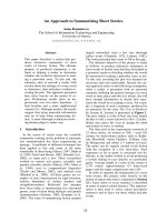
Figure 1: (a) General configuration for a multiuser system with point-to-point links. In this example, there are 5 simultaneous commu-
nications and 4 terminals. (b) Typical configuration in a multiuser MIMO-OFDM scenario with 3 users or communications. T here are 5
terminals, where 3 of them are MTs and the other 2 ones are BSs.
the design of the beamformers was presented to minimize
the total transmit power subject to QoS constraints in terms
of a minimum SNIR for each u ser, although it was shown
that it might converge to a local suboptimum solution. In all
these papers, the channel was assumed to be frequency flat,
although in our work we have extended the desig n to the case
of a multicarrier modulation in a frequency selective chan-
nel.
This paper is structured as follows. In Section 2, the sys-
tem and signal models for the MIMO-OFDM multiuser sce-
nario are presented, in addition to deducing the expression of
the optimal receive beamvectors as a function of the transmit
beamvectors. The application of the SA algorithm in order
to jointly design all the transmit beamvectors is presented in
Section 3,whereasinSection 4 other classical suboptimum
designs based on GS and AM algorithms are proposed. Fi-
nally, in Sections 5 and 6, some simulation results and con-
clusions are shown, respectively.
2. SYSTEM AND SIGNAL MODELS
Consider a wireless scenario in which several terminals coex-
ist in the same area. Among these terminals, K communica-
tions or links are established and access the common channel
at the same time and in the same frequency band. As pre-
viously stated, the adopted modulation technique is an N-
carriers OFDM. All the terminals in the system are allowed
to have multiple antennas and each of them is able to trans-
mit and/or receive. We consider that each communication or
link is assigned to two terminals, where one of them is the
transmitter and the other one is the receiver.
2.1. MIMO multiuser system and signal models
As it has been stated previously, the system model for the K
communications is based on a joint beamforming approach
at the transmitter and the receiver, where the beamvectors
corresponding to different communications or links are al-
lowed to be different. In this scenario, there exists a set of
terminals, where we have n ot differentiated between BSs and
MTs since all the terminals are allowed to transmit and/or
receive simultaneously. All the terminals in the system are
numbered and the quantity of terminals may be different
from the number of established links (see Figure 1). Let t(k)
represent the terminal responsible for transmitting the infor-
mation corresponding to the kth link, whereas r(k) is the ter-
minal receiving this information. In Figure 1, we show some
examples of these kinds of systems (a generic example and a
more concrete one). Equation (1) represents the signal model
for the received snapshot vector for the kth link, that is, it is
the received signal model at the r(k)th terminal and the nth
Joint Beamforming Design in a MIMO-OFDM Multiuser System 213
Input
data
S/P converter
N
Prebeamforming
b
(k)
0
(k)
N
.
.
.
IFFT (OFDM
modulator) +
cyclic prefix +
P/S
.
.
.
N
.
.
.
IFFT (OFDM
modulator) +
cyclic prefix +
P/S
.
.
.
Cyclic prefix
removal + S/P
+ FFT(OFDM
demodulator)
N
.
.
.
.
.
.
Cyclic prefix
removal + S/P
+ FFT(OFDM
demodulator)
N
.
.
.
a
N
Postbeamforming
a
(k)
0
N
P/S converter
Output
data
.
.
.
.
Figure 2: Architecture of the transmitter and the receiver for the kth communication or link based on joint beamforming.
carrier [17] (see Figure 2 in which we represent the architec-
ture of the transmitter and the receiver for the kth link based
on joint beamforming):
y
(r(k))
n
(t) =
K
l=1
H
(t(l),r(k))
n
b
(l)
n
s
(l)
n
(t)+n
(r(k))
n
(t), (1)
where we have assumed that the length of the cyclic prefix is
higher than or equal to the channel order [3].Thesizeofthe
vectors y
(r(k))
n
(t)andb
(l)
n
is equal to the number of antennas
at the r(k)th and the t(l)th terminals, respectively. The trans-
mit beamvector applied to s
(l)
n
(t)isrepresentedbyb
(l)
n
,where
s
(l)
n
(t) is the transmitted data at the nth carrier during the
tth OFDM symbol for the lth link. The transmitted symbols
are assumed to have a normalized energy: E
{|s
(l)
n
(t)|
2
}=1
(E
{·} stands for the mathematical expectation). The matrix
H
(t(l),r(k))
n
represents the MIMO channel response at the nth
carrier between the t(l)th and the r(k)th terminals. We have
also considered that H
(i,i)
n
= 0,foralli, which means that the
ith terminal is not receiving the signal transmitted by itself.
Finally, the vector n
(r(k))
n
(t) models the contribution of noise
plus interferences from outside the system at the r(k)th re-
ceiver and the nth carr ier. The associated covariance matr ix is
represented by Φ
(r(k))
n
= E{n
(r(k))
n
(t)n
(r(k))
n
H
(t)}, where (·)
H
stands for complex conjugate t ranspose. This signal model is
quite general and can easily fit in with many known systems
including, but not limited to, the cellular environments, both
for uplink and downlink.
2.2. Single-user receiver optimization
In this subsec tion, the attention is focused on the design of
the receive beamvectors. For every link and carrier, a linear
combiner a
(k)
n
is applied to the set of received samples col-
lected in the snapshot vector y
(r(k))
n
(t). The hard estimate of
the transmitted symbol s
(k)
n
(t) for the kth link during the tth
OFDM symbol is, therefore, b ased on a hard mapping ap-
plied to the output of the receive beamvector, that is,
s
(k)
n
(t) =
dec{a
(k)
n
H
y
(r(k))
n
(t)}. The optimum receive beamvector a
(k)
n
is
the one maximizing the output SNIR. The expression of the
optimum beamvector is widely known and corresponds to
the Wiener matched filter [4, 17], which can be formulated as
follows assuming that the transmit beamvectors are known:
a
(k)
n
= α
(k)
n
R
(k)
n
−1
H
(t(k),r(k))
n
b
(k)
n
,(2)
R
(k)
n
= Φ
(r(k))
n
+
K
l=1, l=k
H
(t(l),r(k))
n
b
(l)
n
b
(l)
n
H
H
(t(l),r(k))
n
H
,(3)
where R
(k)
n
is the total interference plus noise covariance ma-
trix seen at the receiver for the kth link, and α
(k)
n
is a scalar
factor that does not affect the SNIR and can be calculated to
have an equalized equivalent channel a
(k)
n
H
H
(t(k),r(k))
n
b
(k)
n
= 1,
α
(k)
n
= (b
(k)
n
H
H
(t(k),r(k))
n
H
R
(k)
n
−1
H
(t(k),r(k))
n
b
(k)
n
)
−1
.Asitcanbe
seen in (2), the optimum receive beamvector for the kth
link depends on both the transmit beamvector for the same
link b
(k)
n
and all the other ones {b
(l)
n
}
l=1, ,K
l
=k
, since the covari-
ance matrix R
(k)
n
depends on the transmit beamvectors for
all the other links different from k.Thisproducesacoupling
effect that makes difficult the optimization of the tr ansmit
beamvectors. In the following section, we explicitly focus the
attention on the joint design of all the transmitters. By using
this design criterion for the receivers, the SNIR at the output
of the receive beamformer for the kth link and the nth carrier
can be shown to be as follows [17]:
SNIR
(k)
n
= b
(k)
n
H
H
(t(k),r(k))
n
H
R
(k)
n
−1
H
(t(k),r(k))
n
b
(k)
n
. (4)
Taking into account this result, in OFDM the effective
or mean BER is defined as the uncoded BER averaged over
all the subcarriers, BER
(k)
= (1/N)
N−1
n
=0
Q(
k
m
SNIR
(k)
n
),
where we have assumed that all the interferences are approx-
imately Gaussian distributed, Q(x)
= (1/
√
2π)
∞
x
e
−t
2
/2
dt,
and k
m
is a parameter depending on the modulation applied
to each subcarrier (for BPSK, k
m
= 2).
3. SIMULATED-ANNEALING-BASED TRANSMITTER
OPTIMIZATION
The last section was devoted to the optimum design of the
receive beamvectors assuming that the transmit beamvec-
tors were known, obtaining the closed-form solution cor-
responding to the Wiener matched filter [4]. Now, the at-
tention is focused on the joint design of all the transmit
beamvectors for all the users and all the OFDM carriers.
214 EURASIP Journal on Wireless Communications and Networking
When designing the transmit beamvectors, an objective
function or optimization criterion has to be identified, as
well as a set of design constraints. Obviously, a desirable ob-
jective is the minimization of the total transmit power, since
in wireless networks, high transmit powers imply a shorter
lifetime of the MTs. In the case of using several antennas, the
power used for transmitting the information symbol corre-
sponding to the nth carrier of the kth user is proportional to
b
(k)
n
2
. Taking this into account, the total transmit power P
T
can be expressed as
P
T
b
(k)
n
k=1, ,K
n
=0, ,N−1
=
K
k=1
N
−1
n=0
b
(k)
n
2
=
K
k=1
N
−1
n=0
b
(k)
n
H
b
(k)
n
.
(5)
Besides the objective function, additional constraints are
necessary in order to avoid the trivial solution minimizing
the transmit power b
(k)
n
= 0. In this paper, two kinds of
constraints are proposed. The first one refers to the mini-
mum QoS for each communication or link and is manda-
tory, whereas the other is related to the maximum individual
transmit powers for a concrete set of terminals. This set of
terminals can be empty and, therefore, the individual trans-
mit power constraints are optional.
(i) QoS constraints: these constraints are formulated in
terms of the maximum mean BER for each link and
can be expressed as follows:
BER
(k)
≤ γ
(k)
, k = 1, , K,(6)
where γ
(k)
is the maximum permitted BER for the kth
link and, therefore, is an input parameter of the op-
timization problem. This formulation generalizes the
results presented in [9] for an MC-CDMA system, and
in [11, 14, 15, 16] for flat fading channels, where the
QoS constraints were formulated in terms of the SNIR
instead of the mean BER. In [10, 12, 13], the trans-
mit power was stated to be a prefixed value and the
goal was the optimization of the mean quality of all
the users in terms of capacity, minimum MSE, and so
forth, and therefore, no QoS could be guaranteed for
each link. In all cases, the proposed algorithms for the
most general scenario, comprising several BSs and MTs
with multiple antennas, were shown to be inefficient
in the sense that they might find local suboptimum
solutions instead of the global optimum one, because
of the nonconvex behaviour of the optimization prob-
lems.
(ii) Individual t ransmit power constraints: in addition to
the QoS constraints, optional constraints can also be
included regarding the maximum individual transmit
powers for some terminals. This is specially useful for
MTs with a power-limited battery in an uplink trans-
mission. Let Υ be the set of terminals to which these
constraints are applied. They can be formulated as
P
(i)
T
=
K
k=1, t(k)=i
N
−1
n=0
b
(k)
n
2
≤ P
(i)
max
, i ∈ Υ,(7)
where P
(i)
max
represents the maximum transmit power
for the ith terminal. These kinds of constraints have
notbeenconsideredinanyoftheworksreferencedin
this paper.
Currently, there exists no closed form solution for this
extremely complicated constrained optimization problem,
sinceitisnotconvex[7]. Although in this case the objec-
tive function
K
k=1
N−1
n=0
b
(k)
n
2
is convex in the optimiza-
tion variables b
(k)
n
, the constraint set is not. In order to prove
this last statement, we consider the simplest example corre-
sponding to only one user using an OFDM modulation with
only one carrier. For this simple case, the maximum BER
constraint is equivalent to a minimum SNIR constraint. We
assume that H
= I and that Φ
n
= I (we obviate the sub and
super indexes to facilitate the notation). According to this,
the QoS constraint can be formulated as b
H
b ≥ SNIR
min
.
This constraint can be represented geometrically as the exte-
rior of a sphere in the variable vector b,which,obviously,is
not convex. Due to the nonconvex behaviour of the problem,
if a classical GS or AM method is applied to find the opti-
mal design, a local minimum may be found instead of the
global optimum in the constraint set. Since we are interested
in finding the global optimum design in order to provide a
reference system to be used as a comparative framework for
other suboptimal designs, we have decided to exploit the SA
algorithm. SA is a very powerful heuristic tool able to find
the global optimum design even when the objective function
or the constraint set is not convex. As stated in the intro-
duction, some previous works have proposed GS techniques,
such as in [9], or AM methods [10, 11, 13, 15, 16], among
others. T he main problem of these techniques is that they are
not able to find the global optimum design due to the non-
convex behaviour of the problem, as it was clearly shown in
[11] and other works. Besides, in GS and AM techniques, it
may be extremely difficult to include any kind of constraint,
although in the case of SA this can be done easily, as will be
shown later in this section. Specifically, for the case of GS, the
constraints are required to be differentiable, although this is
not necessary in SA.
In this paper, the existence of a feasible solution is as-
sumed, that is, a collection of transmit beamvectors that sat-
isfies al l the constraints simultaneously. In case that a feasible
solution does not exist, the algorithm will not converge to
any acceptable design.
The SA algorithm has analogies with the annealing of
solids in physics and thermodynamics, as has been explained
in [8]. The main objective of the annealing process in physics
is to obtain a solid with a “perfect” particles arrangement,
that is, a perfect str u cture, so that the energy of the links be-
tween these particles is minimized. In order to obtain this
perfect structure, initially the solid has to be melted by heat-
ing it, that is, until all the particles have total freedom of
movement. Once this “hot” state is attained, the tempera-
ture has to be lowered until the “perfect” state is obtained,
in which the particles have no movement. If the cooling pro-
cess is done very quickly, the obtained state may be not the
one with the minimum energy and, therefore, is not perfect.
Joint Beamforming Design in a MIMO-OFDM Multiuser System 215
If the minimum energy is desired, then the system has to be
cooled very slowly, so that the particles have “enough time”
to be placed in their optimal positions.
In our problem, in each step of the iterative algorithm
there is a collection of transmit b eamvectors
{b
(k)
n
}
k=1, ,K
n
=0, ,N−1
,
which is called the current solution. Given the current solu-
tion, which is equivalent to a concrete particles arrangement
or a state in the annealing process in physics, a new solution
or collection of beamvectors is proposed. If it is “better” than
the original one, then it is retained as the current one. On
the contrary, if it is “worse,” then the proposed solution is
accepted with a certain probability. That means that “worse”
solutions may be accepted. This mechanism, which is called
hill climbing, is extremely important so as to avoid a subop-
timal solution or local minimum. The parameter that con-
trols this acceptance probability is the temperature T,asin
the case of the annealing in physics. The higher the tempera-
ture, the higher the acceptance probability. The temperature
is lowered step by step, so that asymptotically, only “better”
solutions are accepted and a minimum is approached. The
meaning of “better” and “worse” is based on the definition of
acostfunction f (
·) that depends on the transmit beamvec-
tors and is directly related to the total transmit power. This
function corresponds to the energy of a state in physics and
its minimization is the goal of the annealing process. As in
the thermodynamics annealing process, if the temperature is
lowered very slowly, the optimum state with the minimum
energy, that is, the global minimum of the total transmit
power, can be achieved, as desired initially.
Here we provide the description and all the basic ideas of
the SA algorithm proposed to solve the already stated opti-
mization problem.
(i) Cost function definition:
f
b
(k)
n
= P
T
b
(k)
n
+
α
T
K
k=1
log
BER
(k)
γ
(k)
+
2
+
α
T
i∈Υ
log
P
(i)
T
P
(i)
max
+
2
,
(8)
where (x)
+
= max(x, 0). This cost function, which
also depends on the temperature T, is equal to the
total transmit power plus a quadratic penalty term.
This penalt y term takes into account whether the BERs
are greater than the maximum permitted ones, and
whether the individual transmit powers are greater
than those specified. Besides, this penalty term is in-
versely proportional to the temperature, since in the
simulations it has been shown that this rule performs
quitewellintermsofconvergencespeed.AsT is low-
ered, the penalty term is increased and, therefore, the
acceptance of solutions that do not fulfill the con-
straints is asymptotically avoided. The parameter α is
a proportional factor for the penalty term and its value
has been adjusted by simulations to α
= 100 in or-
dertohavegoodconvergenceproperties.Thepenalty
term is based on relative comparisons of the BERs and
the transmit powers with the maximum permitted val-
ues by means of the log(
·) function. These kinds of
comparisons have been chosen, since it has been ob-
served experimentally that they behave better than ab-
solute comparisons. Note, however, that other kinds of
penalty functions could have been used.
(ii) Proposed solut ion generation:
b
(k)
n
= b
(k)
n
+ w
(k)
n
, w
(k)
n
∼ CN
0, σ
2
b
I
,
n
= 0, , N −1, k = 1, , K.
(9)
The proposed solutions are generated by applying
independent complex circularly symmetric Gaussian
noise with v ariance σ
2
b
to the components of the trans-
mit beamvectors. This noise is used to generate any
possible collection of transmit beamvectors in a con-
tinuous solution space. Note that there is a difference
when compared to the problems for which SA was ini-
tially applied, in which the solution space was discrete
[8]. The acceptance ratio is monitored for every value
of T. In case that it is lower than 0.1for5times,the
variance of the Gaussian noise is lowered by means of
an exponential profile (σ
2
b
← 0.95σ
2
b
). This is done in
this way as it has been shown experimentally that this
rule improves the convergence speed of the algorithm.
(iii) Probability of acceptance of the proposed solution:
Prob
= exp
−
1
T
f
b
(k)
n
− f
b
(k)
n
+
. (10)
This acceptance probability corresponds to the
Metropolis criterion, as described in [8], and is re-
lated to the Maxwell-Boltzmann approximation of the
Fermi-Dirac distribution describing the energy of an
electron in different levels. This criterion was initially
used in thermodynamics in order to simulate a ther-
mal equilibrium process. It was shown that, using this
criterion, the system could arrive at the minimum pos-
sible energy, that is, to the optimum state, if the tem-
perature was lowered slowly. This philosophy was af-
terwards adopted in the SA algorithm, as shown in this
paper, as an efficient criterion to find the global mini-
mum of nonconvex problems.
(iv) System “cooling”:
T
←− βT, β
∼
=
0.99. (11)
As described in this equation, the temperature is low-
ered very slowly by means of a decreasing exponen-
tial rule, as described in [8]. This value of β has been
chosen since in the simulations it has been shown to
provide good convergence properties, while still guar-
anteeing that the global optimum solution is attained.
As seen in (10), the hotter the system, the higher
the acceptance probability. As a consequence, when
the temperature is high, most of the proposed trans-
mit beamvectors are accepted, which means they are
searching over the range of all the possible spatial
216 EURASIP Journal on Wireless Communications and Networking
Its objective is to find an initial value of the temperature T, so that the number of accepted solutions is higher than 95%.
(1) T
= 1, σ
2
b
is set equal to the mean power necessary at the transmitters to attain the required QoS assuming no interference
among the users (experimentally it has been shown to have good convergence properties). The initial transmit b eamvectors
are set equal to al l zero vectors.
(2) Propose 100 solutions. Measure the number of nonaccepted solutions N
na
.
(3) If N
na
< 95, then T ← 2T andgotostep(2).IfN
na
= 100, then T ← 0.9T and go to step (2). In any other case, end.
Algorithm 1: Initialization in the SA algorithm.
They correspond to the application of the SA algorithm.
(1) L
ar
= 0: initialization of the counter corresponding to the number of times that the acceptance ratio is lower than 10%.
(2) Propose 100 solutions. Measure the number of nonaccepted solutions N
na
. Update the temperature: T ← 0.99T.
(3) If N
na
< 10, then L
ar
← L
ar
+1.IfL
ar
= 5, then σ
2
b
← 0.95σ
2
b
andgotostep(1).Inanyothercase,gotostep(2).
The algorithm finishes when the value of the cost function has stabilized and a minimum has been achieved.
Algorithm 2: Main iterations of the SA algorithm.
directions. When the temperature is lowered, this
range is reduced and the accepted transmit beamvec-
tors begin to look for the best spatial directions, that
is, for the spatial directions that couple the maximum
power towards the desired terminal while reducing the
interference towards the other ones.
In the SA algorithm, initial ly the temperature T has to
be high enough so that most of the proposed solutions are
accepted. The initial transmit beamvectors are set equal to
all zero vectors. Note, however, that the initialization of the
beamvectors is not important since in the first iterations
most of the proposed solutions are accepted and the variance
of the noise to generate and propose new solutions is very
high. In this paper, 100 iterations are run for every value of
T. As a summary, the main steps of the algorithm are pre-
sented and briefly detailed in Algorithms 1 and 2.
4. OTHER CLASSICAL SUBOPTIMUM TECHNIQUES
In the last section, the SA technique has been proposed to
find the global optimum design of the stated constrained op-
timization problem. In this section, we present two alterna-
tive algorithms based on the GS and the AM methods.
4.1. Lagrange-gradient search transmitter
optimization
A classical approach different from the SA consists in the uti-
lization of a gradient technique, although, as it has been al-
ready said, the main drawback of this family of algorithms is
that they may converge to local suboptimum designs. In or-
der to compare the SA with other classical approaches, in this
section we propose an iterative gradient technique based on
the classical Lagrange multipliers method and the quadratic
penalty term [9, 18]. This technique is based on the defini-
tion of a Lagrangian expression L. When formulating the
Lagrangian expression and the penalty term, we take into ac-
count the fact that the optimal solution implies that the QoS
are fulfilled with equality. Under this assumption, that can be
shown easily, the Lagr angian expression can be formulated as
L
=P
T
+λ
K
j=1
log
BER
( j)
γ
( j)
2
+
i∈Υ
log
P
(i)
T
P
(i)
max
+
2
. (12)
The equations that show how to update the transmit
beamvectors and the penalty factor λ correspond to the well-
known gradient descent and ascent techniques, as also used
in [9]
b
(k)
n
←− b
(k)
n
− µ∇
b
(k)
n
H
L,
λ
←− λ + µ
K
j=1
log
BER
( j)
γ
( j)
2
+
i∈Υ
log
P
(i)
T
P
(i)
max
+
2
,
(13)
where µ is the step size parameter that has to be adjusted to
cope with the tradeoff between the convergence speed and
the convergence itself. The initial beamvectors can be calcu-
lated assuming that there is no interference between users, as
shown in [10, 17]. The initial value for the penalty factor λ is
set equal to 0. Here, the necessary expressions to calculate the
gradient
∇
b
(k)
n
H
L are provided. In order to facilitate the no-
tation, we assume an uplink scenario with several MTs trans-
mitting to a single BS, which is responsible for the detection
of the symbols transmitted by all the MTs. The modulation
of the subcarriers is BPSK. In this scenario, the matrix H
(k)
n
represents the response of the MIMO channel at the nth car-
rier between the kth MT and the BS. The extension to other
kinds of scenarios is quite simple by using very similar ex-
pressions. The function δ
Υ
(k)isdefinedasδ
Υ
(k) = 1, k ∈ Υ,
and δ
Υ
(k) = 0, k ∈ Υ:
∇
b
(k)
n
H
L = b
(k)
n
+2λ
K
j=1
1
BER
( j)
log
BER
( j)
γ
( j)
∇
b
(k)
n
H
BER
( j)
+ δ
Υ
(k)2λ
b
(k)
n
P
(k)
T
log
P
(k)
T
P
(k)
max
+
.
(14)
Joint Beamforming Design in a MIMO-OFDM Multiuser System 217
(1) Initialization: set all the transmit beamvectors proportional to the maximum eigenvectors of the matrices
H
(t(k),r(k))
n
H
Φ
(r(k))
n
−1
H
(t(k),r(k))
n
, that is, without taking into account the interferences from other users. Calculate the
power allocation (either uniform or maxmin) to satisfy the QoS constraints.
(2) Repeat until convergence.
(i) Calculate all the covariance matrices (see (3)).
(ii) Calculate all the transmit beamvectors as the maximum eigenvectors of H
(t(k),r(k))
n
H
R
(k)
n
−1
H
(t(k),r(k))
n
and the
corresponding power allocation satisfying the QoS constraints.
Algorithm 3: Application of the AM algorithm.
The expression of ∇
b
(k)
n
H
BER
( j)
depends on j. Firstly, we
give the expression for the case j
= k:
∇
b
(k)
n
H
BER
(k)
=−
1
N
√
2π
exp
− SNIR
(k)
n
×
1
2SNIR
(k)
n
H
(k)
n
H
R
(k)
n
−1
H
(k)
n
b
(k)
n
.
(15)
For the case j
= k, the expression is as follows, where the
matrix inversion lemma has been used:
∇
b
(k)
n
H
BER
( j)
=−
1
N
√
2π
exp
−
SNIR
( j)
n
×
1
2SNIR
( j)
n
∇
b
(k)
n
H
SNIR
( j)
,
∇
b
(k)
n
H
SNIR
( j)
=
H
(k)
n
H
R
( j,k)
n
−1
H
(k)
n
b
(k)
n
1+b
(k)
n
H
H
(k)
n
H
R
( j,k)
n
−1
H
(k)
n
b
(k)
n
2
×
b
( j)
n
H
H
( j)
n
H
R
( j,k)
n
−1
H
(k)
n
b
(k)
n
2
−
b
( j)
n
H
H
( j)
n
H
R
( j,k)
n
−1
H
(k)
n
b
(k)
n
1+b
(k)
n
H
H
(k)
n
H
R
( j,k)
n
−1
H
(k)
n
b
(k)
n
× H
(k)
n
H
R
( j,k)
n
−1
H
( j)
n
b
( j)
n
,
R
( j,k)
n
= Φ
n
+
K
l=1, l=j, l=k
H
(l)
n
b
(l)
n
b
(l)
n
H
H
(l)
n
H
.
(16)
As previously stated, one of the main drawbacks of the
GS technique is that a local suboptimum design may be
found. This could be solved by using different initial sets of
beamvectors, selected randomly. Note, however, that this in-
creases the computational load and does not guarantee a suc-
cessful result.
4.2. Alternate & maximize transmitter optimization
Finally, another classical solution that has been used previ-
ously by many authors in papers such as [10, 13, 15, 16],
among others, is the AM algorithm. In our problem, the
SNIR for a concrete user and carrier depends, not only on
the beamvector for the considered user, but also on all the
transmit beamvectors for all the other users through the co-
variance matrix, as shown in (3)and(4). The AM algorithm
is an iterative technique, so that in each step the beamvectors
associated to a concrete user are desig ned assuming that the
beamvectors of all the other users are fixed, that is, assuming
that the noise plus interferences covariance matrix is known.
Obviously, when a beamvector for a user is designed, the co-
variance matrix for the other users change and, therefore, the
technique has to be applied iteratively until convergence is at-
tained.
In this subsection, we provide the description of an AM
algorithm in which we only take into account the QoS con-
straints, but not the individual transmit power constraints,
since their inclusion in the algorithm is extremely difficult. In
each step, the optimum transmit beamvector maximizing the
SNIR corresponds to the eigenvector associated to the max-
imum eigenvalue of the matrix H
(t(k),r(k))
n
H
R
(k)
n
−1
H
(t(k),r(k))
n
(see a complete proof of this in [10, 17]). Besides this, an
adequate power allocation among the carriers of the OFDM
modulation has to be calculated, so that the QoS constraint
in terms of the maximum BER is fulfilled. In this paper, we
have used two different power allocation policies: the uni-
form and the maxmin techniques, as completely described in
[17].
Algorithm 3 shows the main steps of the AM technique,
including the beamvectors initialization. The main disadvan-
tage of this algorithm, as commented previously and in pa-
pers such as [13, 15, 16], is that the obtained solution may
be a local suboptimum design instead of the global optimum
one, since the optimization problem is not convex. Besides,
there is no a priori guarantee of convergence. A possible so-
lution would consist in using different random initializations
for the transmit beamvectors. Note, however, that this is an
ad hoc procedure that does not control and guarantee that
the global optimum design is obtained.
5. SIMULATION RESULTS
In this section, we simulate an uplink scenario with 3 MTs
and 1 BS. The OFDM modulation consists of N
= 16 car-
riers and both MTs and BS have 5 antennas. The QoS con-
straints in terms of the mean BER are 10
−3
,10
−3
,and10
−2
and α = 100, as stated in Section 3. The noise is assumed to
be white both in the time and space domains, with a nor-
malized variance equal to 1, that is, Φ
(r(k))
n
= I. The simula-
tions and algorithms are applied to a sing le realization of the
multiple OFDM-MIMO channels, although we do not pro-
vide the numerical expressions of the channel matrices for
the sake of clarity.
218 EURASIP Journal on Wireless Communications and Networking
10
10
10
5
10
0
Power (dB)
012345678910
×10
10
Flops
User 1
User 2
User 3
10
1
10
0
8.599.5
×10
10
(a)
10
10
10
5
10
0
Power (dB)
012345678910
×10
10
Flops
User 1
User 2
User 3
10
1
10
0
8.599.5
×10
10
(b)
10
0
10
−100
10
−200
10
−300
Mean BER
012345678910
×10
10
Flops
User 1
User 2
User 3
10
−2
10
−3
8.599.5
×10
10
(c)
10
0
10
−100
10
−200
10
−300
Mean BER
012345678910
×10
10
Flops
User 1
User 2
User 3
10
−2
10
−3
8.599.5
×10
10
(d)
Figure 3: Powers of the MTs for SA in scenario 1. (b) Powers of the MTs for SA in scenario 1 including a power constraint in MT1. (c) BERs
of the MTs for SA in scenario 1. (d) BERs of the MTs for SA in scenario 1 including a power constraint in MT1.
In the first scenario, it is assumed that the path loss is
very similar for all the users. In Figures 3a and 3c, we show
the evolution of the powers allocated to the three users and
the mean BERs as the iterations of the SA algorithm run, con-
cluding that the proposed technique is able to find a design
fulfilling the constraints when no individual power restric-
tions are applied. The optimum power corresponding to the
first user is 8.45 W, and the total power is 20.1 W. If a power
constraint is applied to the first user is equal to 8 W, then the
results are those shown in Figures 3b and 3d. The main con-
clusion is that, in this case, the SA algorithm allocates 7.6 W
to the first user, whereas the other ones increase their corre-
sponding power consumption. As it is also shown, the global
transmit power has increased up to 20.8 W. This increase of
the total transmit power is normal, as in the second example,
a more restrictive constraint has been applied and, therefore,
the optimization has to be carried out over a more limited set
of transmit beamvectors fulfilling the constraints.
In Figure 4, a set of results are presented for the case of a
scenario in which the third user has a path loss with respect
to the first two users equal to 12 dB. In this example, no in-
dividual transmit power constraint has been considered. Fig-
ures 4a and 4c corresponds to the application of SA, whereas
Figures 4b and 4d corresponds to the GS algorithm with a µ
parameter, that is, the step size, equal to 0.001. The main con-
clusion is that with the same computational load or number
of floating point operations, the SA algorithm can fulfill the
constraints, whereas the GS technique decreases importantly
the convergence speed as the solution approaches these con-
straints. This is because the penalty terms applied in the La-
grangian expression (12) are quadratic and, therefore, when
calculating the derivatives in a point near from the fulfill-
ment of the constraints, these derivatives tend to zero. Simu-
lations concerning the application of the AM algorithm have
also been done for two different power allocation techniques,
uniform and maxmin [17]. From the simulations, it is con-
cluded that AM has a high convergence speed. Table 1 shows
a summary of the results for all the techniques. The conclu-
sion is that GS does not find a solution fulfilling the con-
straints, whereas AM does not have this problem, as in the
case of SA. The main drawback is that the necessary trans-
mit power is higher for AM than for SA, concluding that a
local suboptimum design has been found. Indeed, and as ex-
plained in [15], the nonconvexity and the number of local
minima increases as more BSs and MTs are coexisting in the
same area.
Joint Beamforming Design in a MIMO-OFDM Multiuser System 219
10
10
10
5
10
0
Power (dB)
012345678910
×10
10
Flops
User 1
User 2
User 3
10
2
10
1
10
0
8.599.5
×10
10
(a)
10
2
10
1
10
0
Power (dB)
012345678910
×10
10
Flops
User 1
User 2
User 3
(b)
10
0
10
−100
10
−200
10
−300
Mean BER
012345678910
×10
10
Flops
User 1
User 2
User 3
10
−2
10
−3
8.599.5
×10
10
(c)
10
−1
10
−2
10
−3
Mean BER
012345678910
×10
10
Flops
User 1
User 2
User 3
(d)
Figure 4: (a) Powers of the MTs for SA in scenario 2. (b) Powers of the MTs for GS in scenario 2. (c) BERs of the MTs for SA in scenario 2.
(d) BERs of the MTs for GS in scenario 2.
Table 1: Power and BER for SA, GS, and AM.
MT 1 power MT 2 power MT 3 power Total power MT 1 BER MT 2 BER MT 3 BER
SA 10.2 W 8.7 W 54.5 W 73.4 W 10
−3
10
−3
10
−2
GS 9.6 W 8 W 46.5 W 64.1 W 1.01 ·10
−3
1.01 ·10
−3
1.42 ·10
−2
AM-maxmin 8.3 W 6.8 W 63.6 W 78.7 W 10
−3
10
−3
10
−2
AM-uniform 9.1 W 7.9 W 65.5 W 82.5 W 10
−3
10
−3
10
−2
6. CONCLUSIONS
As a general conclusion, in this paper a MIMO-OFDM mul-
tiuser system based on a joint beamforming approach has
been proposed. The objective was the joint design of the
beamvectors associated to all the established communica-
tions or links, taking as the optimization criterion the min-
imization of the total transmit power subject to maximum
mean BER and individual transmit power constraints. It has
been shown that this problem is not convex and, therefore,
the application of the SA technique has been proposed, in
addition to classical GS and AM methods. The SA has been
shown to be able to find the optimum solution and, there-
fore, the obtained design may be used as a comparative
framework for other suboptimum solutions. Other classical
techniques, such as GS and AM, also presented in this pa-
per, may have problems related to the convergence speed and
the fact that local suboptimum designs may be found. Be-
sides, GS and AM cannot always include every kind of con-
straint, whereas in SA this can be easily done by using ade-
quate penalty functions.
Although SA has been shown to be a powerful tool to
cope with the optimization of nonconvex problems, such as
the one presented in this paper, there exist other heuristic
220 EURASIP Journal on Wireless Communications and Networking
approaches that should be also considered as possible strate-
gies. Among these techniques, some examples can be given,
such as the genetic algorithms (GA) [19] or taboo search
(TS) approaches. In both cases, the techniques are based on
a random generation of possible solutions, such as in the
SA algorithm, and are also able to find the optimum so-
lution, even if the problem is not convex. The main dif-
ference between SA and the GA-TS strategies is that the
last two techniques transform the solution space, that is,
the set of possible transmit beamvectors, into a space com-
posed of “bits” by means of an encoding process. Once this
transformation has been performed, the optimization prob-
lem is solved in this new transformed solution space. Fi-
nally, the solution in terms of transmit beamvectors should
be found by transforming or decoding the solution in the
coded space. Further work is to be done on the application
of these techniques in order to evaluate whether the compu-
tational load of the optimization problem can be decreased
while still guaranteeing that the global optimum design is
found.
ACKNOWLEDGMENTS
The authors would like to thank the anonymous review-
ers that have contributed to improve this paper with their
helpful comments. This work was partially supported by the
Spanish Government under projects TIC2002-04594-C02-
01 (GIRAFA, jointly financed by FEDER) a nd FIT-070000-
2003-257 (MEDEA+ A111 MARQUIS), and by the European
Commission under projects WIDENS (contract 507872) and
IST-2002-2.3.1.4 (NEWCOM). This paper was presented in
part at the XI European Signal Processing Conference (EU-
SIPCO) 2002.
REFERENCES
[1] ETSI, “Broadband radio access networks (BRAN); HIPER-
LAN Type 2; Physical (PHY) layer,” TS 101 475 v1.1.1, April
2000.
[2] IEEE, “Part 11: Wireless LAN medium access control (MAC)
and physical layer (PHY),” IEEE Std. 802.11a, December 1999.
[3] Z. Wang and G. B. Giannakis, “Wireless multicarrier commu-
nications,” IEEE Signal Processing Magazine,vol.17,no.3,pp.
29–48, 2000.
[4] J. G. Proakis, Digital Communications, McGraw-Hill, New
York, NY, USA, 3rd edition, 1995.
[5] V. Tarokh, N. Seshadri, and A. R. Calderbank, “Space-time
codes for high d ata rate wireless communication: perfor-
mance criterion and code construction,” IEEE Transactions
on Information Theory, vol. 44, no. 2, pp. 744–765, 1998.
[6] V. Tarokh, H. Jafarkhani, and A. R. Calderbank, “Space-time
block codes from orthogonal designs,” IEEE Transactions on
Information Theory, vol. 45, no. 5, pp. 1456–1467, 1999.
[7] S. Boyd and L. Vandenberghe, Introduction to Convex Opti-
mization with Engineering Applications, Course Notes, Stan-
ford University, Stanford, Calif, USA, 2000.
[8] P. J. M. van Laarhoven and E. H. L. Aarts, Simulated Anneal-
ing: Theory and Applications, Kluwer Academic Publishers,
Boston, Mass, USA, 1987.
[9]T.M.LokandT.F.Wong, “Transmitterandreceiveropti-
mization in multicarrier CDMA systems,” IEEE Transactions
on Communications, vol. 48, no. 7, pp. 1197–1207, 2000.
[10] K K. Wong, R. S K. Cheng, K. B. Letaief, and R. D. Murch,
“Adaptive antennas at the mobile and base stations in an
OFDM/TDMA system,” IEEE Transactions on Communica-
tions, vol. 49, no. 1, pp. 195–206, 2001.
[11] J H. Chang, L. Tassiulas, and F. Rashid-Farrokhi, “Joint
transmitter receiver diversity for efficient space division mul-
tiaccess,” IEEE Transactions on Wireless Communications, vol.
1, no. 1, pp. 16–27, 2002.
[12] W.Rhee,W.Yu,andJ.M.Cioffi, “The optimality of beam-
forming in uplink multiuser wireless systems,” IEEE Trans-
actions on Wireless Communications, vol. 3, no. 1, pp. 86–96,
2004.
[13] S. Serbetli and A. Yener, “Transceiver optimization for mul-
tiuser MIMO systems,” IEEE Transactions on Signal Processing,
vol. 52, no. 1, pp. 214–226, 2004.
[14] H. Boche and M. Schubert, “A general duality theory for
uplink and downlink beamforming,” in IEEE 56th Vehicular
Technology Conference (VTC ’02), vol. 1, pp. 87–91, Vancou-
ver, British Columbia, Canada, September 2002.
[15] E. Visotsky and U. Madhow, “Optimum beamforming using
transmit antenna arrays,” in IEEE 49th Vehicular Technology
Conference (VTC ’99), vol. 1, pp. 851–856, Houston, Tex, USA,
July 1999.
[16] M. Bengtsson, “A pragmatic approach to multi-user spatial
multiplexing,” in Proc. 2nd IEEE Sensor Array and Multi-
channel Signal Processing Workshop Proceedings (SAM ’02),pp.
130–134, Rosslyn, Va, USA, August 2002.
[17] A.Pascual-Iserte,A.I.P
´
erez-Neira, and M. A. Lagunas, “On
power allocation strategies for maximum signal to noise and
interference ratio in an OFDM-MIMO system,” IEEE Trans-
actions on Wireless Communications, vol. 3, no. 3, pp. 808–820,
2004.
[18] D. P. Bertsekas, Constrained Opt imization and Lagrange Mul-
tiplier Methods, Computer Science and Applied Mathematics.
Academic Press, New York, NY, USA, 1982.
[19] D. E. Goldberg, Genetic Algorithms in Search, Optimization,
and Machine Learning, Addison-Wesley, Reading, Mass, USA,
1989.
Antonio Pascual-Iserte was born in Barce-
lona, Spain, in 1977. He received the de-
gree in electrical engineering from the Uni-
versitat Polit
`
ecnica de Catalunya (UPC),
Barcelona, in 2000, and was awarded with
the First National Prize of 2000/2001 Uni-
versity Education by the Spanish Ministry
of Education and Science. Currently, he is
working toward the degree in mathematics
and the Ph.D. degree in electrical engineer-
ing. From September 1998 to June 1999, he worked on micropro-
cessor programming with the Electronic Engineering Department,
UPC. From June 1999 to December 2000, he was with Retevision
R&D, Barcelona, Spain, where he worked on the implantation of
the DVB-T and T-DAB networks in Spain. In January 2001, he
joined the Department of Signal Theory and Communications,
UPC, where he worked as a Research Assistant until September
2003 under a grant from the Catalan Government. Since Septem-
ber 2003, he is an Assistant Professor at UPC, Barcelona, Spain.
Currently, he is involved in several national and European research
projects.
Joint Beamforming Design in a MIMO-OFDM Multiuser System 221
Ana I. P
´
erez-Neira was born in Zaragoza,
Spain, in 1967. She received the de-
gree in telecommunication engineering and
the Ph.D. degree from the Universitat
Polit
`
ecnica de Catalunya (UPC), Barcelona,
Spain, in 1991 and 1995, respectively. In
1991, she joined the Department of Signal
Theory and Communications, UPC, where
she carried out research activities in the field
of higher-order statistics and statistical ar-
ray processing. In 1992, she became a Lecturer, and since 1996,
she has been an Associate Professor with UPC, where she teaches
and coordinates graduate and undergraduate courses in statistical
signal processing, analog and digital communications, mathemati-
cal methods for communications, and nonlinear signal processing.
She is the author of nine journal and more than 50 conference pa-
pers in the area of statistical signal processing and fuzzy process-
ing, with applications to mobile/satellite communications systems.
She has coordinated several private, national public, and European
founded projects.
Miguel
´
Angel Lagunas was born in Madrid,
Spain, in 1951. He received the Telecommu-
nication Engineer degree from the Universi-
tat Polit
`
enica de Madrid (UPM), Madrid, in
1973, and the Ph.D. degree in telecommuni-
cations from the Universitat Polit
`
ecnica de
Barcelona (UPB), Barcelona, Spain. From
1971 to 1973, he was a Research Assistant
at the UPM. From 1973 to 1979, he was a
Teacher Assistant, and from 1979 to 1982,
he was an Associate Professor at the UPB. He was a Fullbright
Scholar at the University of Boulder, Boulder, Colorado. Since
1983, he has been a Full Professor at the Universitat Polit
`
ecnica
de Catalunya (UPC), Barcelona, where he teaches courses in signal
processing, array processing, and digital communications. He was
a Project Leader in several research projects. Currently, he is the
Director of the Telecommunications Technological Center of Cat-
alonia (CTTC), Barcelona. His research interests include spectral
estimation, adaptive systems, and advanced front-ends combining
spatial with frequency-time and coding diversity. Dr. Lagunas was
the Vice President for Research of UPC from 1986 to 1989, and Vice
Secretary for Research from 1995 to 1996. He is a Member-at-Large
of EURASIP, and an Elected Member of the Academy of Engineers
of Spain and of the Academy of Science and Arts of Barcelona.