Báo cáo hóa học: " Optimisation of Downlink Resource Allocation Algorithms for UMTS Networks" docx
Bạn đang xem bản rút gọn của tài liệu. Xem và tải ngay bản đầy đủ của tài liệu tại đây (704.23 KB, 6 trang )
EURASIP Journal on Wireless Communications and Networking 2005:4, 573–578
c
2005 Michel Terr
´
eetal.
Optimisation of Downlink Resource Allocation
Algorithms for UMTS Networks
Michel Terr
´
e
Conservatoire National des Arts et M
´
etiers (CNAM), 292 r ue Saint Martin, 75003 Paris, France
Email:
Emmanuelle Vivier
Institut Sup
´
erieur d’Electronique de Par is (ISEP), 28 rue Notre Dame des Champs, 75006 Paris, France
Email:
Bernard Fino
Conservatoire National des Arts et M
´
etiers (CNAM), 292 r ue Saint Martin, 75003 Paris, France
Email: fi
Received 22 October 2004; Revised 3 June 2005; Recommended for Publication by Sayandev Mukherjee
Recent interest in resource allocation algorithms for multiservice CDMA networks has focused on algorithms optimising the
aggregate uplink or downlink throughput, sum of all indiv idual throughputs. For a given set of real-time (RT) and non-real-time
(NRT) communications services, an upper bound of the uplink throughput has recently been obtained. In this paper, we give the
upper bound for the downlink throughput and we introduce two downlink algorithms maximising either downlink throughput,
or maximising the number of users connected to the system, when orthogonal variable spreading factors (OVSFs) are limited to
the wideband code division multiple access (WCDMA) set.
Keywords and phrases: resource management, capacity optimisation, code division multiple access, OVSF, multiservices.
1. INTRODUCTION
Third generation (3G) wireless mobile systems like UMTS
provide a wide variety of packet data services and will proba-
bly encounter an even greater success than already successful
existing 2G systems like GSM [1]. With the growing number
of services, the optimisation of resource allocation mecha-
nisms involved in the medium access control (MAC) layer is
adifficult aspect of new radio mobile communications sys-
tems. The resource allocation algorithm allocates the avail-
able resources to the active users of the network. These re-
sources could be radio resources: they are time-slots in the
case of a 2.5G network like (E)GPRS, but in a 3G network like
UMTS, using WCDMA technology, they are spreading codes
and power. Each user of data services can request, depend-
ing on his negotiated transmission rate, a spreading code
of variable length with a corresponding transmission power
at each moment. In a cell, we have real-time (RT) commu-
nications services that are served with the highest priority
This is an open access article distributed under the Creative Commons
Attribution License, which permits unrestricted use, distribution, and
reproduction in any medium, provided the original work is properly cited.
and non-real-time (NRT) communications services that are
served with the lowest priority. Having allocated resources to
the RT services, the base station then has to allocate resources
to NRT servi ces. In this paper we consider two possible cri-
teria: the greatest number of allocated NRT services and the
maximisation of the downlink throughput [2].
Most of notations used in this paper are close to those
of [3, 4, 5, 6] where the downlink case was analysed, and of
[7, 8, 9, 10] concerning the uplink case.
Compared with these previous papers, we take into con-
sideration the problem of the orthogonal variable spread-
ing factors (OVSF) of UMTS terrestrial radio access network
(UTRAN) solution where spreading factors are limited to the
wideband code division multiple access (WCDMA) finite set
[11, 12, 13, 14]. This constraint was neither introduced in
[5, 6] where algorithms presented are then perfectly suited
for the UTRAN context, nor in [10] where the spreading fac-
tor set used is infinite and yields to a complex search table
algorithm.
The UTRAN finite set constraint for spreading factors
was previously addressed in [15] through the description of
a real-time UMTS network emulator but without developing
an optimal allocation algorithm.
574 EURASIP Journal on Wireless Communications and Networking
Following approach presented in [9] for the uplink, we
first introduce in the paper the optimal downlink upper
bound, in order to compare performances of proposed al-
gorithm with this upper bound.
The remainder of the paper is organised as follows: main
notations are introduced in Section 2. The upper bound for
the aggregate downlink throughput is given in Section 3.The
solution for the powers to the NRT flows is given in Section 4.
Two allocation algorithms are detailed in Section 5.The
proof of the optimality of the proposed “downlinkDSF-U al-
gorithm” is given in Section 6. Simulations results are finally
presented in Section 7.
2. NOTATIONS
We consider a cell with Q RT terminals and M NRT termi-
nals. Let 0 ≤ p
i
≤ P
max
and N
i
∈ N
+
be the transmis-
sion power and spreading factor of the ith flow at slot t.
P
max
is the maximum transmission power of the base sta-
tion. N
+
is the set of possible spreading factors. Let g
i
>
0 be the channel gains between the base station and the
ith user and I
i
the interference level for the ith user. This
interference level includes the background, thermal noise
power, and the intercell interference power. I
i
does not in-
clude the intracell interference power due to other flows (RT
and NRT) of the cell.
Index i = 1, 2, , Q is devoted to RT terminals while in-
dex i = Q +1,Q +2, , Q + M is devoted to NRT terminals.
For e ach NRT user, we introduce a new g
i
variable repre-
senting its own “channel quality” defined by the ratio of its
channel gain to its interference level: g
i
= g
i
/I
i
. Without loss
of generality, we assume g
Q+1
≥ g
Q+2
≥···≥g
Q+M
,solower
index values correspond to higher channel quality.
We assume that the coherence time of the most rapidly
varying channel is greater than the duration of a time slot, so
that the variations of the channel are small enough to con-
sider that the gains are constant over a time slot.
We introduce Γ
i
representing the target signal-to-noise-
plus-interference ratio requested for RT or NRT services.
Finally we introduce the constant 0 ≤ α ≤ 1, representing
the loss of orthogonality of downlink spreading codes. We
consider α = 0 for an additive white Gaussian noise channel,
where codes stay orthogonal at the input of the terminal re-
ceiver, and typically α = 1/2 for a multipath channel, where
orthogonality is partially lost.
Therefore, for the ith terminal we have
Γ
i
=
N
i
p
i
g
i
1+α
P
T
− p
i
g
i
,(1)
where P
T
=
Q+M
k=1
p
k
represents the sum of allocated pow-
ers either to RT terminals (k ∈ [1, Q]) or to NRT terminals
(k ∈ [Q +1,Q + M]).
Constraints are 0 ≤ P
T
≤ P
max
and N
i
∈ N
+
. The ag-
gregate downlink throughput of NRT terminals Ω
↓
NRT
is pro-
portional to the sum of the inverse of the allocated spread-
ing factors: Ω
↓
NRT
∝
Q+M
i=Q+1
1/N
i
. In this paper we consider
that all NRT terminals correspond to the same service cate-
gory and request all the same QoS and then the same signal-
to-noise-plus-interference ratio. We then have Γ
i
= Γ for all
i ∈ [Q, Q +1].
3. UPPER BOUND FOR THE DOWNLINK
THROUGHPUT
The upper bound for the downlink throughput is straightfor-
ward. We allocate powers to RT fl ows considering that resid-
ual available power is then allocated to the first NRT fl ow
(having the highest channel quality). Actually we can first
consider the choice between allocating the maximal power
either to the first NRT flow with a spreading factor N
Q+1
or
to the second NRT flow with a spreading factor N
Q+2
.Due
to the constant term equal to one in (1) and the nondecreas-
ing function f (x) = ax/(1 + bx), a, b>0, it appears that
g
Q+1
>g
Q+2
leads to 1/N
Q+1
> 1/N
Q+2
, so the first solution
gives a higher throughput. We now consider a solution allo-
cating powers to both flows Q+1 and Q+2. It is then obvious
that the power allocated to the second NRT flow generates a
higher throughput if it is transferred to the first NRT flow.
Generalising this result to more than two flows gives the so-
lution for maximising the downlink throughput. The ideal
and minimal spreading factor N
Q+1
for the fist NRT flow is
obtained using (1)by
N
Q+1
=
Γ
1+αP
RT
g
Q+1
P
max
− P
RT
g
Q+1
,(2)
where P
RT
=
Q
k=1
p
k
represents power allocated to RT ter-
minals.
This allocation leads to the fol low ing optimal upper
bound for the downlink throughput Ω
↓∗
NRT
∝ 1/N
Q+1
.How-
ever, N
Q+1
has no reason to be in the set of values N
+
=
{4, 8,16, 32, 64, 128, 256, 512} that have been normalised for
UTRAN downlink [11, 12, 13, 14]. Consequently, Ω
↓∗
NRT
is
a theoretical upper bound for Ω
↓
NRT
. In this paper we pro-
pose an optimal downlink allocation algorithm where allo-
cated spreading factors belong to the finite set of available
spreading factors of UTRAN.
4. POWERS ALLOCATED FOR NRT FLOWS
We propose to split the allocation problem in two
steps. First we identify a set of spreading factors N =
(N
1
, N
2
, , N
Q
, N
Q+1
, , N
Q+M
) suited to the UTRAN con-
straints and, in a second step, the corresponding powers
p = (p
1
, p
2
, , p
Q
, p
Q+1
, , p
Q+M
) are computed. For the
spreading factors allocation, RT services define rigorously the
Q first spreading factors (N
1
, N
2
, , N
Q
) and the degree of
freedom of the allocation algorithm concerns only the M last
spreading factors (N
Q+1
, , N
Q+M
).
For the power allocation, whatever the RT or the NRT
terminal i taken into consideration, (1)mustbeverified,
Resource Allocation Algorithms for UMTS 575
we then have
p
i
=
Γ
i
1+αP
T
g
i
αΓ
i
g
i
+ N
i
g
i
. (3)
So by summation,
P
T
=
Q+M
i=1
p
i
=
Q+M
i=1
Γ
i
1+αP
T
g
i
αΓ
i
g
i
+ N
i
g
i
. (4)
Afterstraightforward derivation, we obtain
P
T
=
Q+M
i=1
Γ
i
/g
i
αΓ
i
+ N
i
1 − α
Q+M
i=1
Γ
i
/(αΓ
i
+ N
i
)
. (5)
If 1−α
Q+M
i=1
Γ
i
/(αΓ
i
+N
i
) > 0andP
T
≤ P
max
, the solution is
“feasible” and, once spreading factors are allocated, p
i
is di-
rectly obtained by combining (5)and(3). If constraints are
not checked, the allocation is not possible and the through-
put must be decreased through an increase of the spreading
factors.
5. NRT SPREADING FACTORS ALLOCATION
ALGORITHMS
In this section we propose two allocation algorithms. In both
cases we first allocate RT terminals, then we continue with
NRT terminals sorted in ascending order (numbered from
Q +1toQ + M, corresponding to the channel quality g
Q+1
to g
Q+M
). Both algorithms check that powers obtained by
solving (5)leadto0 ≤ P
T
≤ P
max
. If this condition is
not checked, the algorithm stops and keeps the last correct
allocation. The first algorithm, so-called downlink discrete
spreading factor down (downlinkDSF-D), first allocates the
highest spreading factor (SF=512) to the greatest number of
NRT terminals in order to maximise the number of served
terminals. If possible, it then decreases progressively all the
spreading factors, starting with the terminal with the high-
est channel quality in the cell (N
Q+1
), then N
Q+2
,andso
forth. If the allocation is not possible, the algorithm ends
and the spreading factor of the processed terminal keeps its
previous value. In the paper we note N
i
=∞if no spread-
ing factor is allocated to the corresponding terminal. Obvi-
ously, this algorithm maximises the number of users simul-
taneously served and tr ies, if possible, in a second time, to
increase as much as possible the downlink throughput but
without decreasing the number of served terminals. The sec-
ond algorithm, so called downlink discrete spreading factor
up (downlinkDSF-U) proceeds terminal by terminal and in
order to maximise the aggregate downlink throughput, it al-
locates the lowest spreading factor (SF=4) to the terminal
with the highest channel quality in the cell (N
Q+1
), then to the
second (N
Q+2
), and so forth. If the allocation is not possible,
the spreading factor of the processed terminal is increased
until a correct set of {N
i
} is found; otherwise,the terminal
is rejected and the algorithm stops. This second algorithm
optimises the downlink throughput. The proof is presented
in the next section.
6. OPTIMALITY OF THE DOWNLINKDSF-UP
ALGORITHM
Definition 1 (definition of an arranged solution). Arranging
asolutionN = (N
1
, , N
Q
, N
Q+1
, ,N
Q+M
) consists in con-
sidering only M last spreading factors corresponding to NRT
terminals and for them (1) reordering spreading factors in
increasing order, and (2) in the case of two equal factors
N
k
= N
k+1
(>N
min
) to recombine N
k
by N
k
/2andN
k+1
by
∞. The operation is reiterated as many times as possible. At
the end of the process the solution is arranged. Throughputs
of the original solution and its arranged version are equals.
Except for N
i
= N
min
= 4, any NRT spreading factor cannot
appear twice in the last spreading factors set of the arranged
solution.
Theorem 2. For any solution N = (N
1
, , N
Q
, N
Q+1
, ,
N
Q+K
) the corresponding arranged solution leads to a reduction
of the transmitted power P
T
=
Q+K
i=1
p
i
.
Proof of Theorem 2. (A) Permutation: we consider two so-
lutions N
1
= (N
1
, , N
Q
, , N
i
, , N
j
, )andN
2
=
(N
1
, , N
Q
, , N
j
, , N
i
, )withi< jand, by hypothesis,
g
i
≥ g
j
and N
i
≤ N
j
. We introduce the corresponding trans-
mitted powers P
1
T
and P
2
T
. Using (5), we notice that denomi-
nators of P
1
T
and P
2
T
are equal (we considered Γ = Γ
i
= Γ
j
for any NRT terminal). For the numerator we notice that
M + Q − 2 terms are similar for these two powers. We then
have to analyse 4 terms in order to co mpare powers corre-
sponding to these two different spreading factors allocations:
sign
P
2
T
− P
1
T
= sign
1
g
i
N
j
+ αΓ
+
1
g
j
N
i
+ αΓ
−
1
g
i
N
i
+ αΓ
−
1
g
j
N
j
+ αΓ
,
(6)
and after some easy derivation,
sign
P
2
T
− P
1
T
=
sign
N
i
g
j
+ N
j
g
i
− N
j
g
j
− N
i
g
i
. (7)
Since N
i
≤ N
j
,wecanwriteN
j
= N
i
+ ∆N
ij
with ∆N
ij
≥ 0.
Then sign(P
2
T
− P
1
T
) = sign(∆N
ij
(g
i
− g
j
)). Since by hypoth-
esis g
i
≥ g
j
, we have directly sign(P
2
T
− P
1
T
) ≥ 0, then
P
2
T
≥ P
1
T
.
(B) Recombining: we consider two solutions
N
1
= (N
1
, , N
Q
, , N
i
, ∞, )andN
2
=
(N
1
, , N
Q
, ,2N
i
,2N
i
, ) with the corresponding
transmitted powers P
1
T
and P
2
T
. Using (5)wecannote
P
1
T
= Num
1
/ Den
1
and P
2
T
= Num
2
/ Den
2
.
576 EURASIP Journal on Wireless Communications and Networking
(i) Analysis of Num
1
− Num
2
:
Num
2
− Num
1
=
Γ
g
i
αΓ +2N
i
+
Γ
g
i+1
αΓ +2N
i
−
Γ
g
i
αΓ + N
i
,
Num
2
− Num
1
=
ΓN
i
g
i
− g
i+1
+ αΓ
2
g
i
g
i
g
i+1
αΓ + N
i
αΓ +2N
i
.
(8)
As g
i
>g
i+1
,wehaveNum
2
> Num
1
.
(ii) Analysis of Den
2
− Den
1
:
Den
2
− Den
1
=
−2αΓ
2N
i
+ αΓ
−
−αΓ
N
i
+ αΓ
,
Den
2
− Den
1
=
−α
2
Γ
2
2N
i
+ αΓ
N
i
+ αΓ
.
(9)
Formula (9) gives directly Den
2
< Den
1
. Finally P
2
T
>P
1
T
.
After successive reordering and p ermuting we obtain the ar-
ranged version of the original solution. It has same through-
put, lower P
T
,andanyN
i
= 4 can appear only once.
Remark 1. If a solution N
2
is possible, it means that 0 ≤ P
2
T
≤
P
max
,thenwehaveDen
1
> Den
2
> 0andP
1
T
<P
2
T
≤ P
max
.
With (5) we conclude that the arranged version N
1
of any
possible solution N
2
exists always and is possible.
Theorem 3. The dow nlinkDSF-U algorithm maximises the
aggregate downlink throughput.
Proof of Theorem 3. We consider an exhaustive search among
all possible solutions. We identify the solution N
best
giving
the highest throughput and minimising, for this throughput,
the transmitted power P
T
.BecauseP
T
is minimal, this so-
lution is necessarily arranged (cf. Theorem 2). We now com-
pare spreading factors used by this optimal solution N
best
and
those used by the downlinkDSF-U algorithm N
Up
.Ifwecan
find an NRT index i such that N
best
i
>N
Up
i
then, since W-
CDMA spreading factors are successive powers of 2, we have
N
best
i
≥ 2N
Up
i
. The corresponding throughput difference is
thengreaterorequalto(2N
Up
i
)
−1
.Atthispoint,eveniffor
all j>i, N
Up
j
=∞, this throughput loss cannot be bal-
anced by spreading factors corresponding to indices j>i
of the “best” solution. To check this, we just have to con-
sider that for all j ≥ i, N
best
j
≥ 2
j−i
N
best
i
. Then the aggregate
throughput Ω
best
i+1→M
, due to spreading factors i+1 to M of the
“best” solution, is proportional to
M
j=i+1
(1/N
best
j
). This ad-
ditional throughput is maximal when each spreading factor
is replaced by its minimal value. Accordingly,
Ω
best
i+1→M
≤
M
j=i+1
1
2
j−i
1
N
best
i
. (10)
Using N
best
i
≥ 2N
Up
i
,(10)becomes
Ω
best
i+1→M
≤
M
j=i+1
1
2
j−i+1
1
N
Up
i
. (11)
Then (with m = j − i),
Ω
best
i+1→M
≤
1
2N
Up
i
M−i
m=1
1
2
m
. (12)
And finally,
Ω
best
i+1→M
<
1
2N
Up
i
. (13)
In order to prove Theorem 3,wejusthavetocompare
spreading factors N
best
and N
Up
.
For i = Q + 1, we have three possibilities.
(i) N
best
Q+1
>N
Up
Q+1
:asmentionedearlierthiscaseisimpos-
sible because it leads to Ω
Up
> Ω
best
.
(ii) N
best
Q+1
<N
Up
Q+1
: this case is impossible b ecause the
downlinkDSF-U algorithms have minimised N
Up
Q+1
.
(iii) N
best
Q+1
= N
Up
Q+1
: so the two solutions are equivalent.
Having finally N
best
Q+1
= N
Up
Q+1
, we can now consider i = Q +2
and so forth foll owing the same argument. At the end, we
obtain N
best
= N
Up
. The downlinkDSF-U algorithm gives
the optimal solution, which maximises then the downlink
throughput.
7. SIMULATION RESULTS
RT and NRT terminals are uniformly distributed in the cell
at distances from the base station from 325 m–1.2km. In
order to determine the channel gains, we chose Okumura-
Hata propagation model in an urban area with f = 2 GHz,
h
base station
= 40 m, and h
terminal
= 1.5m. Let P
max
= 10 W
and I
inter
=−63 dBm (equivalent to 6 base stations situated
2.4 km away from the base station and transmitting at P
max
).
Γ
RT
and Γ
NRT
are set to7.4 dB. Q issetto50andM varies
from 1–500. Finally, N
RT
= 256 and α = 0.5.
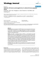
Simulation results represent mean values obtained af-
ter more than thousand trials. Figure 1 illustrates the varia-
tions of Ω
↓∗
NRT
, Ω
↓
NRT
obtained with downlinkDSF-U and with
downlinkDSF-D. Actually, a constant chip rate (including the
radio supervision) of 5120 chips per 10/15 milliseconds is
performed with UTRAN. The aggregate downlink through-
put of NRT terminals is then equal to Ω
↓
NRT
=
M
i=1
7.68/N
i
,
in Mbps (7.68 is the UTRAN 3.84 chip rate doubled with
modulation).
Hence, Ω
↓
NRT
and Ω
↓∗
NRT
are increasing functions of
the number of NRT terminals. Finally, Ω
↓
NRT
varies from
950 kbps to 1.25 Mbps, that is, from 63%–83% of Ω
↓∗
NRT
(equal to 1.5 Mbps).
Resource Allocation Algorithms for UMTS 577
0 50 100 150 200 250 300 350 400 450 500
Number of NRT terminals
600
700
800
900
1000
1100
1200
1300
1400
1500
1600
Throughput (kbps)
Optimal downlink bound
DownlinkDSF-U
DownlinkDSF-D
Figure 1: Ω
↓∗
NRT
and Ω
↓
NRT
obtained with downlinkDSF-U and
downlinkDSF-D.
0 50 100 150 200 250 300 350 400 450 500
Number of NRT terminals
0
10
20
30
40
50
60
70
Number of served NRT terminals
Optimal downlink bound
DownlinkDSF-U
DownlinkDSF-D
Figure 2: Number of simultaneously transmitted NRT services with
downlinkDSF-U and downlinkDSF-D, as a function of the total
number of active NRT services in the cell.
Figure 2 gives the number of simultaneously transmit-
ted NRT services with downlinkDSF-U and downlinkDSF-D
as a function of the total number of active downlink NRT
terminals in the cell. Objectives of the two algorithms are
different and this figure is just an illustration more than a
performance comparison. It is recalled that with the upper
bound, only one NRT terminal is served. It appears that
when downlinkDSF-D is applied, the number of simultane-
ous transmitted NRT services is exactly M when M is low
0 50 100 150 200 250 300 350 400 450 500
Number of NRT terminals
7.5
8
8.5
9
9.5
10
Mean value for the total downlink power (Watt)
DownlinkDSF-U
DownlinkDSF-D
Figure 3: Mean value of the downlink power.
(typically lower than 40). Then, as the base station uses all
its power to reach more and more terminals benefiting from
worse and worse conditions of propagation, it cannot satisfy
all NRT services and the individual rates remain minimum.
Therefore, the aggregate throughput is nearly proportional
to the number of simultaneously served NRT services. On
the opposite, the downlinkDSF-U never transmits simulta-
neously infor mation to more than 4 NRT terminals. Further
more, the probability of having terminals benefiting from
better conditions of propagation increases with M increas-
ing.
Figure 3 gives the total power radiated by the base sta-
tion with respect to the number of active NRT services in
the cell. It appears that the power is close to the 10 W max-
imum value. This maximum value is quickly obtained with
the downlinkDSF-U, while the downlinkDSF-D seems to be
unable to serve a ll terminals and therefore has to choose ter-
minals with good channel quality in order to reach this max-
imal power value.
8. CONCLUSION
In this paper two resource allocation algorithms for the
W-CDMA downlink of UMTS were presented. These algo-
rithms allocate spreading factors in the set {4, 8, 16, 3264,
128, 256,512}; downlinkDSF-U maximises the aggregate
downlink NRT throughput whereas downlinkDSF-D max-
imises the number of simultaneously transmitted NRT ser-
vices. Simulation results have presented comparisons be-
tween an upper bound and the two algorithms in terms
of throughput and number of served terminals. This work
can be extended to the high-speed downlink packet access
(HSDPA) evolution of W-CDMA considering complemen-
tary fr actional (corresponding to the QAM16 modulation)
578 EURASIP Journal on Wireless Communications and Networking
spreading factors and considering the multicodes allocation
principle. The two optimal algorithms are legitimate, respec-
tively, for the operators (seeking maximum revenue) and
users (seeking a fair part of the available resources). We have
shown that these allocations are quite opposite so that trade
off algorithms have to be studied. A suggestion for further
work is to look for maximising throughput in short term
while looking for fair use of the resources among users in
the long term.
REFERENCES
[1] P. Stuckmann, The GSM Evolution: Mobile Packet Data Ser-
vices, John Wiley & Sons, Chichester, UK, 2003.
[2] S. Ramakrishna and J. M. Holtzman, “A scheme for through-
put maximization in a dual-class CDMA system,” IEEE J. Se-
lect. Areas Commun., vol. 16, no. 6, pp. 830–844, 1998.
[3] J H. Wen, J S. Sheu, and J L. Chen, “An optimum downlink
power control method for CDMA cellular mobile systems,” in
Proc. IEEE International Conference on Communications (ICC
’01), vol. 6, pp. 1738–1742, Helsinki, Finland, June 2001.
[4] L. Nuaymi, P. Godlewski, and X. Lagrange, “Power allocation
and control for the downlink in cellular CDMA networks,” in
Proc. 12th IEEE International Symposium on Personal, Indoor
and Mobile Radio Communications (PIMRC ’01), vol. 1, pp.
C-29–C-33, San Diego, Calif, USA, September–October 2001.
[5] D. I. Kim, E. Hossain, and V. K. Bhargava, “Downlink joint
rate and power allocation in cellular multirate WCDMA sys-
tems,” IEEE Transactions on Wireless Communications, vol. 2,
no. 1, pp. 69–80, 2003.
[6] D. I. Kim, E. Hossain, and V. K. Bhargava, “Dynamic rate and
power adaptation for provisioning class-based QoS in cellu-
larmultirateWCDMAsystems,”IEEE Transactions on Wireless
Communications, vol. 3, no. 5, pp. 1590–1601, 2004.
[7] R. Jantti and S L. Kim, “Transmission rate scheduling for the
non-real-time data in a cellular CDMA system,” IEEE Com-
mun. Lett., vol. 5, no. 5, pp. 200–202, 2001.
[8] F. Berggren, S L. Kim, R. Jantti, and J. Zander, “Joint power
control and intracell scheduling of DS-CDMA non real time
data,” IEEE J. Select. Areas Commun., vol. 19, no. 10, pp. 1860–
1870, 2001.
[9] S J. Oh, D. Zhang, and K. M. Wasserman, “Optimal resource
allocation in multiservice CDMA networks,” IEEE Transac-
tions on Wireless Communications, vol. 2, no. 4, pp. 811–821,
2003.
[10] S. A. Jafar and A. Goldsmith, “Adaptive multirate CDMA for
uplink throughput maximisation,” IEEE Transactions on Wire-
less Communications, vol. 2, no. 2, pp. 218–228, 2003.
[11] 3GPP, “General UMTS architecture,” TS 23.101, v. 4.0.0, April
2001.
[12] 3GPP, “UTRAN overall description,” TS 25.401, v.6.1.0, June
2003.
[13] 3GPP, “Spreading and modulation (FDD),” TS 25.213, v.5.2.0,
September 2002.
[14] 3GPP, “Radio resource management strategies,” TS 25.922,
v.5.0.0, March 2002.
[15] O. Sallent, J. Perez-Romero, F. J. Casadevall, and R. Agusti, “An
emulator framework for a new radio resources management
for QoS guaranteed services in W-CDMA systems,” IEEE J.
Select. Areas Commun., vol. 19, no. 10, pp. 1893–1904, 2001.
Michel Te rr
´
e was born in 1964. He re-
ceived the Engineering degree from the
Institut National des T
´
el
´
ecommunications,
Evry, France, in 1987, the Ph.D. degree in
signal processing from the Conservatoire
National des Arts et M
´
etiers, Paris, France,
in 1995, and the Habilitation
`
a Diriger des
Recherches (HDR) degree from the U niver-
sity Paris XIII, Villetaneuse, France, in 2004.
He first had an industrial career in research
and development, mostly in the field of radio communications
at TRT-Philips, Paris, Thal
`
es Communications, Colombes, France,
and Alcatel, Nanterre, France. Since 1998, he has been an Assistant
Professor at the Conservatoire National des Arts et M
´
etiers, Paris.
Dr. Terr
´
eisaSeniorMemberofSEE.
Emmanuelle Vivier was born in 1972.
She received the Engineering degree from
the Institut Sup
´
erieur d’Electronique de
Paris, France, in 1996, the Mast
`
ere de-
gree from the Ecole Nationale Sup
´
erieure
des T
´
el
´
ecommunications, Paris, France, in
1997, and the Ph.D. degree in radio com-
munications from the Conservatoire Na-
tional des Arts et M
´
etiers, Paris, in 2004. She
first had an industrial career in research and
development at Bouygues Telecom, Paris, France. Since 1999, she
has been a Professor at the Institut Sup
´
erieur d’Electronique de
Paris, where she heads the Telecommunication Department.
Bernard Fino was born in 1945. He
received the Engineering D.E. degree
from the Ecole Nationale Sup
´
erieure des
T
´
el
´
ecommunications, Paris, France, in
1968, and the M.S. and Ph.D. degrees in
electrical engineering and computer science
from the University of California, Berkeley,
in 1969 and 1973, respectively. He first
had an indust rial career in research and
development, mostly in the field of radio
communications with Systems Applications, Inc., San Rafael, Calif,
TRT-Philips, Paris, and Alcatel, Colombes, France. He participated
in several projects in standardisation, and in many advanced
research projects while he was leading the Advanced Systems
Department at Alcatel. Since 1995, he has been a Professor at
the Conservatoire National des Arts et M
´
etiers, Paris, where he
is the Chair of radio communications. In 1999, he organised the
European Personal and Mobile Communication Conference in
Paris. Dr. Fino is a Senior Member of IEEE and SEE.