Báo cáo hóa học: " Flexible Analog Front Ends of Reconfigurable Radios Based on Sampling and Reconstruction with Internal Filtering" pdf
Bạn đang xem bản rút gọn của tài liệu. Xem và tải ngay bản đầy đủ của tài liệu tại đây (905.58 KB, 18 trang )
EURASIP Journal on Wireless Communications and Networking 2005:3, 364–381
c
2005 Y. S. Poberezhskiy and G. Y. Poberezhskiy
Flexible Analog Front Ends of Reconfigurable
Radios Based on Sampling and Reconstruction
with Internal Filtering
Yefim S. Poberezhskiy
Rockwell Scientific Company, Thousand O aks, CA 91360, USA
Email:
Gennady Y. Poberezhskiy
Raytheon Company, El Segundo, CA 90245, USA
Email:
Received 27 September 2004; Revised 4 April 2005
Bandpass sampling, reconstruction, and antialiasing filtering in analog front ends potentially provide the best per formance of
software defined radios. However, conventional techniques used for these procedures limit reconfigurability and adaptivity of
the radios, complicate integrated circuit implementation, and preclude achieving potential performance. Novel sampling and
reconstruction techniques with internal filtering eliminate these drawbacks and provide many additional advantages. Several ways
to overcome the challenges of practical realization and implementation of these techniques are proposed and analyzed. The impact
of sampling and reconstruction with internal filtering on the analog front end architectures and capabilities of software defined
radios is discussed.
Keywords and phrases: software defined radios, reconfigurable and adaptive transceivers, sampling, analog signal reconstruction,
antialiasing filtering, A/D.
1. INTRODUCTION
Next generation of software defined radios (SDRs) should
be reconfigurable to support future wireless systems operat-
ing with different existing and evolving communication stan-
dards while providing a wide variety of services over vari-
ous networks. These SDRs should also be extremely adap-
tive to achieve high performance in dynamic communica-
tion environment and to accommodate varying user needs.
Modern radios, virtually all of which are digital, do not
meet these requirements. They contain large analog front
ends, that is, their analog and mixed-signal portions (AMPs)
[1, 2, 3, 4, 5, 6, 7, 8, 9, 10, 11, 12, 13, 14, 15, 16]. The AMPs are
much less flexible and have much lower scale of integration
than the radios’ digital portions (DPs). The AMPs are also
sources of many types of interference and signal distortion. It
can be stated that reconfigurability, adaptivity, performance,
and scale of integration of modern SDRs are limited by their
AMPs. T herefore, only radical changes in the design of the
AMPs allow development of really reconfigurable SDRs.
This is an open access article distributed under the Creative Commons
Attribution License, which permits unrestricted use, distribution, and
reproduction in any medium, provided the original work is properly cited.
It is shown in this paper that the changes in the AMP de-
sign have to be related first of all to the methods of sampling,
reconstr uction, and antialiasing filtering. It is also show n
that implementation of novel sampling and reconstruction
techniques with internal filtering [17, 18, 19, 20, 21, 22, 23]
will make the AMPs of SDRs almost as flexible as their DPs
and significantly improve performance of SDRs. To this end,
conventional architectures of the radio AMPs are briefly ex-
amined in Section 2. It is shown that the architectures that
potentially can provide the best performance have the low-
est flexibility and scale of integration. The main causes of
the conventional architectures’ drawbacks are determined.
In Section 3, novel sampling and reconstruction techniques
with internal filtering are described. The sampling technique
was obtained as a logical step in the development of inte-
grating sample-and-hold amplifiers (SHAs) in [17, 18]. In
[19, 20], it was derived from the sampling theorem. The re-
construction technique with internal filtering was derived
from the sampling theorem in [21]. Initial analysis of both
techniques was performed in [22, 23]. Section 3 contains ex-
amination of their features and capabilities, which is more
detailed than that in [22, 23]. Challenges of these techniques’
implementation and two methods of modification of sam-
pling circuits (SCs) with internal antialiasing filtering are
Flexible Analog Front Ends of Reconfigurable Radios 365
analyzed in Section 4. Since SCs and reconstruction circuits
(RCs) with internal filtering are inherently multichannel,
mitigation of the channel mismatch impact on the perfor-
mance of the SDRs is discussed in Section 5.Architectures
of the AMPs modified to accommodate sampling and recon-
struction with internal filtering are considered in Section 6.
2. CONVENTIONAL ARCHITECTURES OF
THE RADIO AMPS
2.1. AMPs of receivers
In digital receivers, the main purpose of AMPs is to create
conditions for signal digitization. Indeed, AMPs, regardless
of their architectures, carry out the following main func-
tions: antialiasing filtering, amplification of received sig-
nals to the level required for the analog-to-digital converter
(A/D), and conversion of the signals to the frequency most
convenient for sampling and quantization. Besides, they of-
ten provide band selection, image rejection, and some other
types of frequency selection to lower requirements for the
dynamic range of subsequent circuits. Most AMPs of mod-
ern receivers belong to one of three basic architectures: direct
conversion architecture, superheterodyne architecture with
baseband sampling, and superheterodyne architecture with
bandpass sampling. The examples of these architectures are
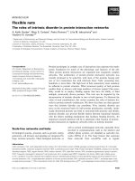
shown in Figure 1.
In a direct conversion ( homodyne) architecture (see
Figure 1a), a radio frequency (RF) section performs prelimi-
nary filtering and amplification of the sum of a desired signal,
noise, and interference. Then, this sum is converted to the
baseband, forming its in-phase (I)andquadrature(Q)com-
ponents. A local oscillator (LO), which generates sine and
cosine components at radio frequency f
r
, is tunable within
the receiver frequency range. Lowpass filters (LPFs) provide
antialiasing filtering of the I and Q components while SHAs
and A/Ds carry out their sampling and quantization. Chan-
nel filtering is performed digitally in the receiver DP. For sim-
plicity, circuits providing frequency tuning, gain control, and
other auxiliary functions are not shown in Figure 1 and sub-
sequent figures. Although integr ated circuit (IC) implemen-
tation of this a rchitecture encounters many difficulties, it is
simpler than that of the architectures shown in Figures 1b
and 1c.
In a superheterodyne architecture with baseband sam-
pling (see Figure 1b), the sum of a desired signal, noise, and
interference is converted to intermediate frequency (IF) f
0
af-
ter image rejection and preliminary amplification in the RF
section. Antialiasing filtering is performed at a fixed IF. This
enables the use of bandpass filters with high selectivity, for
example, surface acoustic wave (SAW), crystal, mechanical,
and ceramic. Then, the sum is converted to the baseband and
its I and Q components are formed.
An example of a superheterodyne architecture with
bandpass sampling is shown in Figure 1c.Inmostcases,
such receivers have two frequency conversions. The 1st IF
is usually selected high enough to s implify image rejection
and reduce the number of spurious responses. The 2nd IF is
RF
section
LPF SHA A/D
I channel
cos 2 πf
r
t
sin 2πf
r
t
LPF SHA
A/D
Q channel
To D P
(a)
RF
section
LPF
IF strip
IF
filter
SHA
A/D
I channel
cos 2 πf
0
t
sin 2πf
0
t
LPF
LPF
LO
SHA
A/D
Q channel
To D P
(b)
RF
section
LPF1
1st IF strip
2nd IF strip
1st IF
filter
2nd IF
filter
1st LO
2nd LO
LPF2
SHA
A/D
To D P
(c)
Figure 1: Receiver AMP architectures: (a) direct conversion archi-
tecture, (b) superheterodyne architecture with baseband sampling,
and (c) superheterodyne architecture with bandpass sampling.
typically chosen to simplify antialiasing filtering and digitiza-
tion. Double frequency conversion also allows division of the
AMP gain between the 1st and 2nd IF strips. This architec-
ture performs real-valued bandpass sampling, representing
signals by the samples of their instantaneous values. In the
DP, these samples are converted to the samples of I and Q
components (complex-valued representation), to make digi-
tal signal processing more efficient.
The results of comparative analysis of the described ar-
chitectures are re flected in Table 1 .Thisanalysisisnotde-
tailed because each basic architecture has many modifica-
tions. For example, superheterodyne architectures may have
366 EURASIP Journal on Wireless Communications and Networking
Tabl e 1: Comparison of various AMP architectures of modern receivers.
Architecture Advantages Drawbacks
Direct conversion
receiver architecture
Absence of spectral images
caused by frequency conversion
Significant phase and amplitude
imbalances between I and Q channels
Better adaptivity compared to
other modern architectures
High nonlinear distortions due to the
fall of substantial part of IMPs within
the signal spect rum
Better compatibility of AMP technology
with IC technology compared to other
architectures
LO leakage that creates interference to
other receivers and contributes to the
DC offset
Relatively low requirements for
SHA and A/D
Relatively low selectivity of
antialiasing filtering
Minimum cost, size, and weight
Direct current (D C) offset caused
by many factors
Flicker noise
Superheterodyne receiver
architecture with
baseband sampling
Radical reduction of LO leakage due
to the offset frequency conversion
High nonlinear distortions due to the
fall of substantial part of IMPs within
signal spectrum
High selectivity of antialiasing filtering
provided by SAW, crystal, mechanical, or
ceramic IF filters
Low adaptivity and reconfigurability of the
receiver AMP due to the use of SAW,
cr ystal, mechanical, or ceramic IF filters
Slight reduction of phase and amplitude imbalances
between I and Q channels compared to the direct
conversion architecture (due to conversion from a
constant IF to zero frequency)
Incompatibility of AMP technology with
IC technology due to the use of SAW,
cr ystal, mechanical, or ceramic IF filters
Reduction of flicker noise due to
lesser gain at zero frequency
Still significant phase and amplitude
imbalances between I and Q channels
Relatively low requirements for
SHA and A/D
Spurious responses due to
frequency conversions
Still significant flicker noise
Superheterodyne receiver
architecture with
bandpass sampling
Radical reduction of LO leakage
due to offset frequency conversion
Low adaptivity and reconfigurability of
the receiver AMP due to the use of SAW,
cr ystal, mechanical, or ceramic IF filters
High selectivity of antialiasing filtering
provided by SAW, crystal, mechanical,
or ceramic IF filters
Incompatibility of AMP technology with
IC technology due to the use of SAW,
cr ystal, mechanical, or ceramic IF filters
Exclusion of phase and amplitude
imbalances between I and Q channels
Still high nonlinear distort ions due to
large input current of SHA
Exclusion of DC offset and flicker
noise
Spurious responses due to
frequency conversions
Minimum IMPs falling within the
signal spectrum
Highest requirements for SHA and
A/D
different number of frequency conversions, and even the ar-
chitectures with a single conversion have different properties
depending on the parameters of their IF strips. For instance,
selection of a low IF in a sing le-conversion architecture en-
ables replacement of high-selectivit y off-chip IF filters with
active filters. This increases flexibility and scale of integra-
tion of an AMP at the expense of more complicated image
rejection.
Despite the absence of some details, Table 1 conclusively
shows that the superheterodyne architecture with bandpass
sampling has advantages that cannot be provided by other
architectures. Indeed, only bandpass sampling minimizes the
number of intermodulation products (IMPs) falling within
the signal spectrum. It also excludes phase and amplitude
imbalances between I and Q channels, DC offset, and flicker
noise. The drawbacks of this architecture have the following
causes. Low adaptivity, reconfigurability, and scale of inte-
gration of the AMPs are caused by inflexibility of the best IF
filters (e.g., SAW, crystal, mechanical, and ceramic) and in-
compatibility of their technology with IC technology. Inflex-
ibility of these filters also does not all ow avoiding spurious
responses. Two times higher sampling frequency required for
bandpass sampling raises requirements for SHA and A/D. At
present, track-and-hold amplifiers (THAs) are usually used
Flexible Analog Front Ends of Reconfigurable Radios 367
as SHAs for bandpass sampling. A THA does not suppress
out-of-band noise and IMPs of all the stages between the an-
tialiasing filter and the THA capacitor. As a result of sam-
pling, these noise and IMPs fall within the signal spectrum.
The impact of this phenomenon is especially significant in
receivers with bandpass sampling. THAs need large input
current because they utilize only a small fraction of signal
energy for sampling. The large input current requires a sig-
nificant AMP gain. This makes sampling close to the antenna
impossible. The large input current also increases nonlinear
distortions. Higher frequency of bandpass signals compared
to baseband ones further increases the required THA input
current and, consequently, nonlinear distortions. THAs are
very susceptible to jitter .
It is important to add that conventional sampling pro-
cedures have no theoretical basis. In contrast, sampling with
internal antialiasing filtering has been derived from the sam-
pling theorem. As shown in Section 3, it eliminates the draw-
backs of conventional sampling.
2.2. AMPs of transmitters
An AMP of a digital transmitter, regardless of its architecture,
has to perform reconstruction filtering, conversion of recon-
structed signals to the RF, and their amplification. Similar
to the receivers, modern transmitters have three basic AMP
architectures: direct up-conversion architecture, offset up-
conversion architecture with baseband reconstruction, and
offset up-conversion architecture with bandpass reconstruc-
tion. Simplified block diagrams of these architectures are
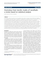
shown in Figure 2.
In a direct up-conversion architecture (see Figure 2a),
modulation and channel filtering are carried out in the trans-
mitter DP using complex-valued representation. The I and
Q outputs of the DP are converted to analog samples by
D/As. After baseband filtering and a mplification of I and
Q components, an analog bandpass sig nal is formed di-
rectly at the transmitter RF. An LO, which generates cos 2πf
r
t
and sin 2πf
r
t, is tunable within the transmitter frequency
range. The formed RF sig nal passes through a bandpass filter
(BPF) that filters out unwanted products of frequency up-
conversion, and enters a power amplifier (PA). This archi-
tecture is the most flexible and suitable for IC implementa-
tion among modern architectures. However, it cannot pro-
vide high performance. The baseband reconstruction causes
significant amplitude and phase imbalances between the I
and Q channels, DC offset, and nonlinear distort ions that re-
duce the accuracy of modulation. The DC offset also causes
the LO leakage through the antenna. Additional problem of
this architecture is that a voltage-controlled oscillator (VCO),
used as an LO, is sensitive to pulling from the PA output.
An AMP architecture with offset up-conversion and
baseband reconstruction (see Figure 2b)isnotsusceptibleto
VCO pulling. It provides better reconstruction filtering than
the previous architecture due to the use of SAW, crystal, me-
chanical, or ceramic IF filters and allows slightly more accu-
rate formation of bandpass signals since it is performed at a
constant IF. If the IF is selected higher than the upper bound
D/A
LPF
I channel
cos 2 πf
r
t
From
DP
D/A LPF
Q channel sin 2πf
r
t
BPF PA
(a)
IF strip
IF
filter
BPF PA
D/A
From
DP
D/A
I channel
Q channel
LPF
LPF
LO
cos 2 πf
0
t
sin 2πf
0
t
(b)
From DP
D/A SHA
1st IF
filter
2nd IF
filter
BPF
PA
1st IF strip
2nd IF strip
1st LO
2nd LO
(c)
Figure 2: Transmitter AMP architectures: (a) direct up-conversion
architecture, (b) offset up-conversion architecture with baseband
reconstruction, (c) offset up-conversion architecture with bandpass
reconstruction.
of the transmitter R F band, the BPF in the AMP can be re-
placed by an LPF. This architecture still has all the drawbacks
related to baseband reconstruction.
These drawbacks are eliminated in an offset up-
conversion architecture with bandpass reconstruction shown
in Figure 2c. Here, a bandpass IF signal is formed digitally
in the DP. This reduces nonlinear distortions and excludes
DC offset and amplitude and phase imbalances between I
and Q channels. As a result, modulation becomes more ac-
curate, and a spurious carrier is not present. However, like
in the case of receivers, these advantages are achieved at the
expense of reduced adaptivity of the AMP and incompatibil-
ity of its technology with IC technology caused by the most
effective IF reconstruction filters. Besides, the sample mode
368 EURASIP Journal on Wireless Communications and Networking
Tabl e 2: Comparison of various AMP architectures of modern transmitters.
Architecture Advantages Drawbacks
Direct
up-conversion
transmitter
architecture
Better compatibility of AMP technology
with IC technology compared to other
modern architectures
Low accuracy of modulation due to
significant phase and amplitude imbalances
between I and Q channels, DC offset, and
nonlinear distortions
Better adaptivity compared to
other modern architectures
LO leakage through the antenna caused
by DC offset and other factors
Pulling voltage-controlled LO from PA output
Offset
up-conversion
transmitter
architecture with
baseband
reconstruction
Insusceptibility to pulling the
voltage-controlled LO from the PA
output
Low accuracy of modulation due to
significant phase and amplitude
imbalances between I and Q channels, DC
offset, and nonlinear distortion
High selectivity of reconstruction
filtering due to the use of SAW, crystal,
mechanical, or ceramic IF filters
Low adaptivity and reconfigurability of AMP
due to the use of SAW, crystal, mechanical, or
ceramic IF filters
Slightly better accuracy of modulation
due to forming a bandpass signal at a
constant IF
Incompatibility of AMP technology with
IC technology due to the use of SAW,
cr ystal, mechanical, or ceramic IF filters
Reduction of LO leakage
Offset
up-conversion
transmitter
architecture
with bandpass
reconstruction
The highest accuracy of modulation due to
radical reduction of phase and amplitude
imbalances between I and Q channels, DC
offset, and nonlinear distortion
Low adaptivity and reconfigurability
of AMP due to the use of SAW,
cr ystal, mechanical, or ceramic filters
Insusceptibility to pulling
voltage-controlled LO from PA
output
Incompatibility of AMP technology with
IC technology due to the use of SAW,
cr ystal, mechanical, or ceramic filters
High selectivity of reconstruction
filtering due to the use of SAW, crystal,
mechanical, or ceramic filters
Incomplete utilization of D/A output
power
Radical reduction of LO leakage High requirements for D/A
length ∆t
s
in a conventional SHA at the D/A output should
meet the condition
∆t
s
≤
1
2 f
0
,(1)
where f
0
is a center frequency of the reconstructed signal,
which coincides with the 1st IF. Condition (1)canbeby-
passed by using SHA with weighted integration. However,
they are not used. Condition (1)doesnotallowefficient uti-
lization of the D/A output current and, consequently, signal
reconstruction close to the antenna.
The results of the comparative analysis of the described
transmitter AMP architectures are reflected in Table 2 . Since
each basic architecture has many modifications, this anal-
ysis is not detailed. However, it shows that the offset up-
conversion architecture with bandpass reconstruction pro-
vides the highest accuracy of modulation. As to the draw-
backs of this architecture, they can be eliminated by imple-
mentation of the proposed reconstruction technique with in-
ternal filtering (see Section 3).
3. SAMPLING AND RECONSTRUCTION WITH
INTERNAL FILTERING
3.1. General
As shown in Section 2, AMPs with bandpass sampling, re-
construction, and filtering provide the best performance of
both receivers and transmitters (see Figures 1c and 2c). At
the same time, conventional methods of sampling, recon-
struction, and filtering limit flexibility of the AMPs, compli-
cate their IC implementation, and prevent achieving poten-
tial performance. Novel sampling and reconstruction tech-
niques with internal filtering [17, 18, 19, 20, 21, 22, 23]al-
low elimination of these drawbacks and provide additional
benefits. These techniques have a strong theoretical founda-
tion because they are derived from the sampling theorem.
They can be used for both bandpass and baseband sam-
pling and reconstruction. However, this paper is mainly fo-
cused on bandpass applications of the proposed techniques
since the techniques are more beneficial for these applica-
tions.
Flexible Analog Front Ends of Reconfigurable Radios 369
−2 f
s
− f
s
0 f
s
2 f
s
f
B
S
u
( f )
(a)
−2 f
s
− f
s
0 f
s
2 f
s
f
G
a
( f )
S
u1
( f )
(b)
Figure 3: Amplitude spectra and the desired AFR: (a) |S
u
( f )|,
(b) |S
u1
( f )| and |G
a
( f )| (dashed line).
3.2. Antialiasing and reconstruction filtering
To better describe operation of sampling and reconstruction
circuits (SCs and RCs) with internal filtering, we first spec-
ify requirements for antialiasing and reconstruction filter-
ing. An antialiasing filter should minimally distort analog
signal u(t) intended for sampling and maximally suppress
noise and interference that can fall within the signal spec-
trum S
u
( f ) as a result of sampling.
When baseband sampling takes place, spectrum S
u
( f )of
a complex-valued u(t), represented by its Iand Q compo-
nents, occupies the interval (see Figure 3a)
[−0.5B,+0.5B], (2)
where B is a bandwidth of u(t). Sampling with frequency
f
s
causes replication of S
u
( f ) with period f
s
(see Figure 3b)
and mapping the whole f -axis for u(t) into the region
[−0.5 f
s
,0.5 f
s
[ for the sampled signal u(nT
s
), where T
s
= 1/f
s
is a sampling period. Thus, antialiasing filter should cause
minimum distortion within interval (2) and suppress noise
and interference within the intervals
kf
s
− 0.5B, kf
s
+0.5B
,(3)
where replicas of S
u
( f ) are located in the spectrum S
u1
( f )
of u(nT
s
). In (3), k is any nonzero integer. In principle, noise
and interference within the gaps between all intervals (3)and
(2) can be suppressed in the DP. However, if these noise and
interference are comparable with or greater than u(t), weak-
ening them by an SC lowers requirements for the resolution
of an A/D and DP. A desired amplitude-frequency response
(AFR) |G
a
( f )| of an antialiasing filter is shown in Figure 3b
by the dashed line.
In the case of reconstruction, it is necessary to suppress
all the images of u(nT
s
) within intervals (3) and minimally
distort the image within interval (2). No suppression within
the gaps between intervals (3)and(2) is usually required.
When bandpass sampling takes place, spectrum S
u
( f )of
real-valued bandpass u(t) occupies the intervals
− f
0
− 0.5B, − f
0
+0.5B
∪
f
0
− 0.5B, f
0
+0.5B
,(4)
−2 f
s
− f
s
− f
0
0 f
s
f
0
2 f
s
f
B
S
u
( f )
(a)
−2 f
s
− f
0
− f
s
0 f
s
f
0
2 f
s
f
G
a
( f )
S
u1
( f )
(b)
Figure 4: Amplitude spectra and the desired AFR: (a) |S
u
( f )|,
(b) |S
u1
( f )| and |G
a
( f )| (dashed line).
where f
0
is a center frequency of S
u
( f ).AplotofS
u
( f )is
shown in Figure 4a. For bandpass sampling and reconstruc-
tion, f
s
usually meets the condition
f
s
=
f
0
floor
f
0
/f
s
+0.5
± 0.25
. (5)
Selection of f
s
according to (5) minimizes aliasing and sim-
plifies both digital forming of I and Q components at the
output of the receiver A/D and digital forming of a band-
pass signal at the input of the transmitter D/A. Therefore, f
s
that meets (5) is considered optimal. When f
s
is optimal, an
antialiasing filter should cause minimum distortion within
intervals (4) and suppress noise and interference within the
intervals
−
f
0
+0.5B +0.5rf
s
, −
f
0
− 0.5B +0.5rf
s
∪
f
0
− 0.5B +0.5rf
s
, f
0
+0.5B +0.5rf
s
,
(6)
where r is an integer, r ∈ [(0.5− 2 f
0
/f
s
), ∞[, r = 0. Figure 4b
shows amplitude spectrum |S
u1
( f )| of u(nT
s
), and the de-
sired AFR |G
a
( f )| of an antialiasing filter for bandpass sam-
pling. T hus, a bandpass antialiasing filter has to suppress
noise and interference within intervals (6) and minimally
distort u(t) within intervals (4). Suppression of noise and in-
terference within the gaps between intervals (4)and(6)isnot
mandatory, but it can be used to lower requirements for the
resolution of an A/D and DP.
Bandpass reconstruction requires only suppression of
u(nT
s
) images within intervals (6) and minimum distortion
within intervals (4).
3.3. Canonical sampling circuits
The block diagrams of two canonical SCs with internal an-
tialiasing filtering are shown in Figure 5.InFigure 5a, an in-
put signal u
i
(t) is fed into L parallel channels, whose out-
puts are in turn connected to an A/D by a multiplexer (Mx).
The spectrum of u
i
(t) is not limited by an antialiasing filter
and includes the spectrum of the signal u(t) that should be
sampled. The lth channel (l ∈ [1, L]) forms all samples with
370 EURASIP Journal on Wireless Communications and Networking
u
i
(t)
u(nT
s
)
1
.
.
.
L
WFG
Control
unit
.
.
.
Mx
A/D
(a)
u
i
(t)
u(nT
s
)
1
.
.
.
L
WFG
Control
unit
.
.
.
Mx
A/D
A/D
(b)
Figure 5: Canonical SCs with internal antialiasing filtering: (a)
single-A/D version and (b) multiple-A/D version.
numbers l + kL,wherek is any integer. The operational cy-
cleofeachchannelisequaltoLT
s
, consists of three modes
(sample, hold, and clear), and is shifted by T
s
relative to the
operational cycle of the previous channel. The length of the
sample mode is equal to T
w
,whereT
w
is the length of weight
function w
0
(t).
During the sample mode, u
i
(t) is multiplied by w
n
(t) =
w
0
(t − nT
s
), and the product is integrated. As a result,
u
nT
s
=
nT
s
+0.5T
w
nT
s
−0.5T
w
u
i
(τ) · w
n
(τ) · dτ. (7)
Equation (7) reflects sampling, accumulation of the signal
energy with weight w
0
(t), and antialiasing filtering with im-
pulse response h(t) = w
0
(nT
s
+0.5T
w
− t). Throughout the
hold mode with length T
h
, a channel is connected to the A/D
that quantizes the channel output. In the clear mode with
length T
c
, the channel is disconnected from the A/D, and the
capacitor of its integrator is discharged. It is reasonable to
allocate T
s
for both hold and clear modes: T
h
+ T
c
= T
s
.A
weight function generator (WFG) simultaneously generates
L−1 copies w
n
(t)ofw
0
(t) because, at any instant, L−1chan-
nels are in the sample mode, and one channel is in the hold or
clear mode. Each w
n
(t) is shifted relative to the previous one
109876543210
−5
0
5
t/T
s
u
i
(t)
(a)
109876543210
−1
0
1
t/T
s
w
n
(t)
(b)
109876543210
−1
0
1
t/T
s
w
n
(t)
(c)
109876543210
−1
0
1
t/T
s
w
n
(t)
(d)
109876543210
−1
0
1
t/T
s
w
n
(t)
(e)
109876543210
−1
0
1
t/T
s
w
n
(t)
(f)
Figure 6: Positions of samples and corresponding w
n
(t).
by T
s
. Positions of samples and corresponding w
n
(t)areillus-
trated by Figure 6 for L = 5. As follows from (7), w
0
(t)deter-
mines filtering properties of SCs. Examples of baseband and
bandpass weight func tions w
0
(t) and the AFRs |G
a
( f )| of the
SCs with these w
0
(t) are shown in Figures 7 and 8,respec-
tively. Since an SC performs finite impulse response (FIR)
filtering with AFR |G
a
( f )|, which is the amplitude spectrum
of w
0
(t), it suppresses interference using zeros of its AFR.
When baseband sampling takes place, the distances between
the centers of adjacent intervals (2)and(3)areequalto f
s
(see Figure 3). To suppress all intervals (3), |G
a
( f )| should
Flexible Analog Front Ends of Reconfigurable Radios 371
21.510.50−0.5−1−1.5−2
1
0.8
0.6
0.4
0.2
0
t/T
s
w
0
(t)
(a)
43.532.521.510.50
0
−20
−40
−60
−80
f/f
s
AFR |G
a
( f )|
(b)
Figure 7: Baseband SC (a) w
0
(t)and(b)AFR|G
a
( f )|,in dB.
have at least one zero within each of them. To achieve this,
condition T
w
≥ 1/f
s
= T
s
is necessary. For bandpass sam-
pling, the distances between the centers of adjacent intervals
(4)and(6)areequalto0.5 f
s
(see Figure 4). Consequently,
T
w
≥ 1/(0.5 f
s
) = 2T
s
is required. When T
h
+ T
c
= T
s
, the
length of the channel operational cycle is
LT
s
= T
w
+ T
h
+ T
c
≥ 3T
s
for bandpass u(t),
LT
s
= T
w
+ T
h
+ T
c
≥ 2T
s
for baseband u(t).
(8)
It follows from (8) that L ≥ 3 is required for bandpass sam-
pling and L ≥ 2 is necessary for baseband sampling. Only
bandpass sampling is considered in the rest of the paper.
In the SC shown in Figure 5b, the required speed of A/Ds
is lower and an analog Mx is replaced with a digital one. This
version is preferable when the maximum speed of the A/Ds
is lower than f
s
, or when L slower A/Ds cost less and/or con-
sume less power than faster one.
3.4. Canonical reconstruction circuits
The block diagrams of canonical RCs with internal filtering
are shown in Figure 9.InFigure 9a, a demultiplexer (DMx)
periodically (with period LT
s
) connects the output of a D/A
to each of L channels. The lth channel (l ∈ [1, L]) processes
samples with numbers l + kL,wherek is any integer. Opera-
tional cycle duration of each channel is equal to LT
s
and de-
layed by T
s
relative to that of the previous channel. The cycle
consists of three modes: clear, sample, and multiply. In the
clear mode, the SHA capacitor is discharged. Then, during
the sample mode, this capacitor is connected to the D/A by
the DMx and charged. Throughout these modes, there is no
signal at the channel output because zero level enters the sec-
ond input of a multiplier from a WFG. The reasonable total
43210−1−2−3−4
1
0.5
0
−0.5
−1
t/T
s
w
0
(t)
(a)
54.543.532.521.510.50
0
−20
−40
−60
−80
f/f
s
AFR |G
a
( f )|
(b)
Figure 8: Bandpass SC (a) w
0
(t)and(b)AFR|G
a
( f )|,in dB.
length of the sample and clear modes is equal to T
s
. In the
subsequent multiply mode w ith duration T
w
, the signal from
the SHA is multiplied by the appropriate copy of w
0
(t) gener-
ated by the WFG, and the product enters an adder that sums
the output signals of all the channels. Since a t any instant,
L − 1 channels are in the multiply mode and one channel is
in the sample or clear mode, the WFG simultaneously gen-
erates L
− 1 copies of w
0
(t), each delayed by T
s
relative to
the previous one. The RC reconstructs an analog signal u(t)
according to the equation
u(t)
≈
∞
n=−∞
u
nT
s
· w
n
(t) =
∞
n=−∞
u
nT
s
· w
0
t − nT
s
.
(9)
It follows from (9) that the RC performs reconstruction fil-
tering with transfer function determined by w
0
(t).
In the version of a canonical RC shown in Figure 9b, digi-
tal words are distributed by a digital DMx among L channels.
Presence of a D/A in each channel allows removal of SHAs.
Here, the channel operational cycle consists of two modes:
convert and multiply. In the first mode, the D/A converts
digital words into samples u(nT
s
), which are multiplied by
w
n
(t) during the multiply mode. This version has the follow-
ing advantages: lower requirements for the speed of D/As,
replacement of an analog DMx by a digital one, and removal
of SHAs.
3.5. Advantages of the SCs and RCs and challenges
of their realization
Both SCs and RCs with internal filtering make AMPs highly
adaptive and easily reconfigurable because w
0
(t), which
determines their filtering properties, can be dynamically
372 EURASIP Journal on Wireless Communications and Networking
Digital
words
u(nT
s
)
D/A DMx
L
WFG
Control
unit
u(t)
1
SHA
SHA
.
.
.
.
.
.
(a)
Digital
words
DMx
L
WFG
Control
unit
u(t)
1
D/A
D/A
.
.
.
.
.
.
u(nT
s
)
(b)
Figure 9: Canonical RCs with internal reconstruction filtering:
(a) single-D/A version and (b) multiple-D/A version.
changed. Internal filtering performed by these structures al-
lows removal of conventional antialiasing and reconstruc-
tion filters or their replacement by wideband low-selectivity
filters realizable on a chip. This makes the AMP technol-
ogy uniform and compatible with the IC technology. The
RCs with internal filtering utilize the D/A output current
more efficiently than conventional devices, then bandpass
reconstruction takes place. The SCs with internal antialiasing
filtering accumulate signal energy in their storage capacitors
during the sample mode. This accumulation filters out jitter
and reduces the charging current of the storage capacitors
by 20–40 dB in most cases. Reduced jitter enables the devel-
opment of faster A/Ds. The decrease in the charging current
lowers both the required gain of an AMP and its nonlinear
distortions. The reduced AMP gain allows sampling close to
the antenna. Smaller charging current also lowers input volt-
age of the SCs. Indeed, although the same output voltage has
to be prov ided by an SC with internal antialiasing filtering
and a conventional SHA, the SC input voltage can be signifi-
cantly lower when the integrator operational amplifier has an
adequate gain. As mentioned in Section 2.1,aconventional
SHA does not suppress out-of-band noise and IMPs of all
the stages between the antialiasing filter and its capacitor. As
a result of sampling, these noise and IMPs fall within the sig-
nal spectrum. The SCs with internal antialiasing filtering op-
erate directly at the A/D input and reject out-of-band noise
and IMPs of all preceding stages. Thus, they perform more
effective antialiasing filtering than conventional structures.
At the same time, practical realization of the SCs and
RCs with internal filtering and their implementation in SDRs
present many technical challenges. Canonical structures of
the SCs and RCs (see Figures 5 and 9) are rather complex.
Therefore, their simplification is highly desirable. This sim-
plification is intended, first of all, to reduce complexity and
number of multiplications.
4. SIMPLIFICATION OF THE SCs AND RCs
4.1. Approaches to the problem
Approaches to simplification of the SCs and RCs depend
on the ways of w
n
(t) generation and multiplications. Ana-
log generation of w
n
(t) implies that multiplications of u
i
(t)
in the SCs and u(nT
s
) in the RCs by w
n
(t)areperformed
by analog multipliers. Since only simple w
n
(t)canbegen-
erated by analog circuits, and this generation is not flexible
enough, digital generation is preferable. When w
n
(t)aregen-
erated digitally, they can be converted to the analog domain
in the WFG (see Figures 5 and 9) or sent to the multipliers in
digital form. In the first case, multiplications in the SCs and
RCs are analog. In the second case, these multiplications can
be carried out by multiplying D/As.
Since digital w
n
(t) have unwanted spectral images, spec-
tral components of an input signal u
i
(t) in the SCs and a re-
constructed signal u(t) in the RCs corresponding to the un-
wanted images should be suppressed. The suppression can
be performed by a wideband filter with fairly low selec tiv-
ity that allows IC implementation. Such a filter is sufficient
because a required sampling r a te of w
0
(t) representation is
much higher than that of the A/D used in a receiver and the
D/A used in a transmitter when bandpass sampling and re-
construction take place. In practice, some kind of prefilter-
ing is performed in all types of receivers, and some kind of
postfiltering is performed in transmitters. Usually, these pre-
filtering and postfiltering can provide the required suppres-
sion. Since prefiltering and postfiltering automatically sup-
press stopbands (6)remotefrompassband(4), internal fil-
tering p erformed by SCs and RCs should first of all sup-
press stopbands (6) closest to the passband. Complexity of
the SCs and RCs, caused by high sampling rate of w
0
(t)rep-
resentation, can be compensated by its low resolution. The
goal is to lower the required resolution of w
0
(t)represen-
tation or to find other means that can reduce multiplying
D/As (or analog multipliers) to a relatively small number of
switches.
Simplification of the SCs and RCs can be achieved by
proper selection of w
0
(t) a nd optimization of their architec-
tures for a given w
0
(t). Below, attention is mostly focused on
the SCs because their practical realization is more difficult
than that of RCs due to higher requirements for their dy-
namic range. Achieving a high dynamic range of multiplica-
tions in the SCs is still a challenging task, although low input
current (compared to conventional SHAs) makes it easier.
Brief information on w
0
(t) selection is provided in
Section 4.2, and two examples of the SC simplification are
described and analyzed in Sections 4.3, 4.4,and4.5.Itis
Flexible Analog Front Ends of Reconfigurable Radios 373
important to emphasize that possible simplifications of the
SCs are not limited to these examples.
4.2. Selectionofweightfunctions
Selection of w
0
(t) is application specific and requires multi-
ple tradeoffs. For example, w
0
(t) that maximizes the dynamic
range of an AMP and w
0
(t) that provides the best internal fil-
tering are different. Indeed, w
0
(t) with rectangular envelope
maximizes the dynamic range due to its minimum peak fac-
tor and the most efficient accumulation of the signal energy,
but it provides relatively poor internal filtering. At the same
time, w
0
(t) that provides the best internal filtering for given L
and f
s
/B has high peak f actor and relatively poor accumula-
tion of sig nal energy. When both features are desirable, w
0
(t)
has to be selected as a result of a certain tradeoff, and this re-
sult can be different depending on specific requirements for
the radio. To provide the best antialiasing filtering for given
L and f
s
/B, w
0
(t) should be optimized using the least mean
square (LMS) or Chebyshev c riterion [23]. Any w
0
(t), op-
timal according to one of these criteria, requires high accu-
racy of its representation and multiplications. This compli-
cates realization of the SCs. Suboptimal w
0
(t) that provide
effective antialiasing filtering with low accuracy of represen-
tation and multiplications are longer than optimal w
0
(t) and,
consequently, require larger L. An increase of f
s
/B simplifies
antialiasing filtering and allows reduction of L or accuracy
of multiplications for a given quality of filtering [20]. Tech-
nology of the SCs and technical decisions regarding these
and other units of the SDRs also influence selection of w
0
(t).
Due to the complexity of these multiple tradeoffs, there is
no mathematical algorithm for w
0
(t) selection, and heur istic
procedures combined with analysis and simulation are used
for this purpose.
In general, a bandpass w
0
(t)canberepresentedas
w
0
(t) = W
0
(t)c(t)fort ∈
− 0.5T
w
,0.5T
w
,
w
0
(t) = 0fort/∈
− 0.5T
w
,0.5T
w
,
(10)
where W
0
(t) is a baseband envelope, and c(t) is a periodic
carrier (with period T
0
= 1/f
0
) that can be sinusoidal or
nonsinusoidal. To provide linear phase-frequency response,
W
0
(t)shouldbeanevenfunction,andc(t) should be an even
or odd function. Assuming that T
w
= kT
s
where k is a nat-
ural number, we can expand c(t) into Fourier series over the
time interval [−0.5T
w
,0.5T
w
]:
c(t) =
∞
m=−∞
c
m
e
jm2πf
0
t
, (11)
where m is any integer and c
m
are coefficients of the Fourier
series. Taking into account (10)and(11), we can write that
within the interval [−0.5T
w
,0.5T
w
],
w
0
(t) = W
0
(t)
∞
m=−∞
c
m
e
jm2πf
0
t
=
∞
m=−∞
w
m0
(t), (12)
where w
m0
(t) are partial weight functions, whose envelopes
are equal to c
m
W
0
(t) and whose carriers are harmonics of f
0
.
The spectra of w
m0
(t) are partial transfer functions G
m
( f ). It
follows from (12) that when f
0
/f
s
is high enough ( f
0
/f
s
> 3
is usually sufficient), the distances between adjacent harmon-
ics of f
0
are relatively large, and overlapping of G
m
( f )does
not notably affect the suppression within those stopbands (6)
that are close to the passband. Since remote stopbands (6)
are suppressed by prefiltering or postfiltering, the simplest
c(t), which is a squarewave, can be used when f
0
/f
s
is suf-
ficient. Combining a squarewave c(t) with an appropriately
selected K-level W
0
(t) allows reducing the multiplying D/As
to a small number of switches. Note that, besides w
0
(t)with
K-level W
0
(t), there are other classes of w
0
(t) that allow us
to do this. If discontinuities in W
0
(t)andc(t)areproperly
aligned and f
0
/f
s
> 3, overlapping of G
m
( f ) can be insig nifi-
cant even if condition T
w
= kT
s
is not met.
The lower f
0
/f
s
is, the more significantly G
m
( f )areover-
lapped. As a result, both W
0
(t)andc(t) influence the filtering
properties of the SCs and RCs. When f
0
/f
s
= 0.25, c(t)has
the greatest impact on their transfer functions. To reduce the
multiplying D/As to a small number of switches in this case,
c(t) should also be a several-level function.
4.3. Separate multiplying by W
0
(t) and c(t)
The following method of the SC realization can be obtained
using separate multiplication of u
i
(t) by the envelope W
0
(t)
and carrier c(t)ofw
0
(t). The nth sample at the output of the
SC is as follows:
u
nT
s
=
0.5T
w
+nT
s
−0.5T
w
+nT
s
u
i
(t)w
0
t − nT
s
dt. (13)
Taking into account (10), we can write
w
0
t − nT
s
= W
0
t − nT
s
· c
t − nT
s
. (14)
When condition (5)ismet,(14)canberewrittenas
w
0
t − nT
s
= W
0
t − nT
s
· c
t − (n mod 4)
T
0
4
. (15)
Since c(t ± T
0
/2) =−c(t),
c
t − nT
s
=
c(t)(−1)
n/2
if n is even,
c
t −
T
0
4
(−1)
(n±1)/2
if n is odd.
(16)
Substituting (16) into (14), and (14) into (13), we obtain
u(nT
s
) =
0.5T
w
+nT
s
−0.5T
w
+nT
s
u
i
(t)W
0
t − nT
s
×
c(t)(−1)
n/2
if n is even
c
t −
T
0
4
(−1)
(n±1)/2
if n is odd
dt.
(17)
374 EURASIP Journal on Wireless Communications and Networking
From
WFEG
From
CU
Mx
A/D
WFEG
CU
C Channel 1
C Channel L
cos 2 πf
0
t
sin 2πf
0
t
u
i
(t)
+
−
+
−
From
CU
.
.
.
.
.
.
Figure 10: Modified SC.
In (16)and(17), “±” corresponds to “±”in(5). In particular,
when c(t) = cos 2πf
0
t,(17) can be rewritten as follows:
u
nT
s
=
0.5T
w
+nT
s
−0.5T
w
+nT
s
u
i
(t)W
0
t − nT
s
×
cos
2πf
0
t
(−1)
n/2
if n is even
sin
2πf
0
t
(−1)
(n±1)/2
if n is odd
dt.
(18)
The algorithm described by (18) can be carried out by the
modified SC shown in Figure 10.Here,u
i
(t)enterstwomul-
tipliers where it is multiplied by cos 2πf
0
t and sin 2πf
0
t.
These multiplications are similar to the beginning of the
procedure used for baseband sampling of bandpass signals
(see Figures 1a and 1b). However, further processing is dif-
ferent. Instead of baseband filtering of the lowest spectral
image after each multiplier, the differential outputs of both
multipliers enter L channels through 4-contact switches. The
switches are necessary because each sample in any channel is
shifted by ±πL/2 relative to the previous one in this channel
when (5) is true. A control unit (CU) provides pro per opera-
tion of the switches. This switching shifts the multiplier out-
put spectral image from zero frequency to f
s
/4. After passing
decoupling capacitor C, it is processed in the channel. Sim-
ilar to the canonical structure in Figure 5a, the operational
cycleofeachchannelisequaltoLT
s
, consists of three modes
(sample, hold, and clear), and is shifted by T
s
relative to the
operational cycle of the previous channel. The difference is
that the channel input signal is multiplied by the appropri-
ate copy W
n
(t)ofW
0
(t) instead of w
n
(t) dur ing the sample
mode. A weight function envelope generator (WFEG) forms
W
n
(t). Each W
n
(t) is shifted relative to the previous one by T
s
to be in phase with the operational cycle of the correspond-
ing channel.
At first glance, the structure in Figure 10 looks even more
complex than the canonical one shown in Figure 5a.How-
ever, appropriate selection of W
0
(t) can significantly simplify
it. For example, when W
0
(t) is a rectangular function, the
WFEG and the multipliers in the channels are unnecessary.
As shown in Figure 11, the modified SC contains only 2 mul-
tipliers for any L in this case. Complexity of the SC can also
From
CU
.
.
.
From
CU
.
.
.
Mx
A/D
CU
C
Channel 1
C
Channel L
cos 2 πf
0
t
sin 2πf
0
t
u
i
(t)
+
−
+
−
Figure 11: Modified SC with rectangular W
0
(t).
be lowered compared to the canonical structures when some
other W
0
(t) are used. Note that single-ended circuits are used
in Figures 10 and 11 only for simplicity of illustration. In
practical applications, differential circuits are preferable.
4.4. Analysis of the modified SC
Many features of the canonical and modified SCs are the
same. Indeed, when the same w
0
(t) are used, their filtering
properties are identical and they accumulate equal amounts
of signal energy. Consequently, they provide the same reduc-
tion of the input cur rent compared to conventional sampling
structures. They are equally adaptive and equally suitable for
IC implementation. However, there is still substantial differ -
ence between them. A canonical SC is not sensitive to DC off-
set, while the outputs of the modified SCs are influenced by
DC offsets in the first two multipliers. Besides, the number
and values of IMPs that fall within the signal spectrum are
higher in the modified SCs than in the canonical ones. In-
deed, multiplication of u
i
(t)byw
n
(t) in each channel of the
canonical SC creates a spectral image at the frequency f
s
/4
because w
n
(t) are centered around corresponding sampling
instants and f
s
meets (5), whereas the first two multiplica-
tions in the modified SCs create baseband spectral images.
Below, this is proven analytically.
Assuming that the DC offset in the multiplier of the lth
channel in a canonical SC is U
l
,wherel = [(n−1) mod L]+1,
we can rewrite (13)as
u
nT
s
=
0.5T
w
+nT
s
−0.5T
w
+nT
s
u
i
(t)w
0
t − nT
s
+ U
l
dt. (19)
It follows from (16)and(19) that
u
nT
s
=
0.5T
w
+nT
s
−0.5T
w
+nT
s
u
i
(t)W
0
t − nT
s
×
c(t)(−1)
n/2
if n is even
c
t −
T
0
4
(−1)
(n±1)/2
if n is odd
dt + U
l
T
w
.
(20)
Flexible Analog Front Ends of Reconfigurable Radios 375
Equation (20)canberewrittenas
u
nT
s
= (−1)
floor [(n+0.5∓0.5)/2]
0.5T
w
+nT
s
−0.5T
w
+nT
s
u
i
(t)W
0
t − nT
s
×
c(t)ifn is even
c
t +
T
0
4
if n is odd
dt + U
l
T
w
,
(21)
where sign “∓” corresponds to “±”in(5). It follows from
(21) that, at the output of a canonical SC, the compo-
nent of the discrete-time signal, caused by the DC offset,
is located at zero frequency, while its desired component
is located at the frequency f
s
/4, as indicated by coefficient
(−1)
floor [(n+0.5∓0.5)/2]
. Thus, the DC offset can be easily fil-
tered out in the receiver DP.
For the modified SC, we can write
u
nT
s
=
0.5T
w
+nT
s
−0.5T
w
+nT
s
W
0
t − nT
s
×
u
i
(t)c(t)+U
1
(−1)
n/2
if n is even
u
i
(t)c
t −
T
0
4
+ U
2
(−1)
(n±1)/2
if n is odd
dt,
(22)
where U
1
and U
2
are DC offsets in the first two multipliers.
Similar to (20), this equation can be rewritten as
u
nT
s
= (−1)
floor [(n+0.5∓0.5)/2]
0.5T
w
+nT
s
−0.5T
w
+nT
s
W
0
t − nT
s
×
u
i
(t)c(t)+U
1
if n is even
u
i
(t)c
t +
T
0
4
+ U
2
if n is odd
dt.
(23)
It follows from (23) that both signal and DC offset compo-
nents after sampling are located at the frequency f
s
/4, as indi-
cated by coefficient (−1)
floor [(n+0.5∓0.5)/2]
. Therefore, the DC
componentcannotbefilteredout.
Thus, D C offset and increased number and values of
IMPs lower the performance of the modified SC compared
to the canonical one. However, their performance is still sig-
nificantly better than that of the conventional baseband sam-
pling. Indeed, the entire signal processing is performed at
zero frequency in the conventional procedure. Consequently,
besides multipliers, all subsequent analog stages contribute
to the increase in the DC offset and nonlinear distortion. In
addition, baseband antialiasing filters create significant phase
imbalance between I and Q channels. In the modified SCs,
signal processing after 4-contact switches is performed at
f
s
/4, and subsequent analog stages do not increase nonlin-
ear distor tions and DC offset. The phase mismatch among
channels of the modified SC is negligible because all clock
impulses are generated in the control unit using the same
reference oscillator, and proper design allows us to mini-
mize time skew. As follows from Section 4.2,cos2πf
0
t and
0.10.080.060.040.020
f
0
/f
s
= 1.25
f
0
/f
s
= 0.75
f
0
/f
s
= 0.25
γ
SER (dB)
20
40
60
80
Figure 12: SER(γ)forvarious f
0
/f
s
.
sin 2πf
0
t in the first two multipliers of the modified SC can
be replaced by squarewaves with frequency f
0
and time shift
of 0.25T
0
= 0.25/f
0
relative to each other when f
0
/f
s
> 3,
and sufficient prefiltering is provided. This replacement fur-
ther simplifies the modified SCs. Thus, the described modi-
fication of the SCs substantially simplifies their realization at
the expense of slightly lower performance.
4.5. Use of orthogonality of WFG outputs
As mentioned in Section 4.2, increase of f
s
/B makes inter-
nal filtering easier and may allow reduction of L. In addition
to reducing L, high-ratio f
s
/B makes possible reducing the
number of multipliers N for given L if f
0
/B is also high. This
possibility is discussed below.
When (5) is true, the carrier of w
n
(t) generated for nth
sample is rotated by ±π/2 relative to the carrier of w
n+2m+1
(t)
generated for (n +2m +1)thsample,wherem is any inte-
ger. Thus, if the envelope of w
0
(t) is rectangular, in some
cases, w
n
(t)andw
n+2m+1
(t) can be sent to the same multi-
plier of the SC or RC with internal filtering even when these
weight functions overlap. This proper ty can be used to re-
duce N for a given L. For example, if T
w
/T
s
= 2(L = 3) and
u(t) = U
0
cos(2πf
0
t + ϕ
0
), one multiplier can be used for all
3 channels and perform, ideally accurate sampling. However,
a pure sinewave cannot carry information. In the case of a
bandpass signal u(t) = U(t)cos[2πf
0
t + ϕ(t)], sampling er-
ror is unavoidable, and signal-to-error power ratio (SER) for
this error is
SER =
16π
2
γ
2
πf
0
T
w
2
− 1
πf
0
T
w
3
∓ 1
2
(24)
when B
1/T
w
.Here,“∓” corresponds to “±”in(5), γ =
B
RMS
/f
0
,andB
RMS
is root mean square bandwidth of u(t).
Figure 12 illustrates the dependence SER(γ) for several values
376 EURASIP Journal on Wireless Communications and Networking
of f
0
/f
s
. Since the spectrum of the error determined above is
generally wider than S
u
( f ), a part of this er ror can be filtered
out in the receiver DP. Therefore, (24) is a lower bound of the
actual SER.
This method of reducing the number of multipliers N
can also be used for L>3 if the corresponding SER is suffi-
ciently small. In this case, the minimally required N is
N =
0.5T
w
T
s
+1 if
0.5T
w
T
s
is even,
0.5T
w
T
s
if
0.5T
w
T
s
is odd.
(25)
For N>1, this method can complicate the channel mis-
match compensation in the receiver DP described in the next
section. It is important to mention that (24)canbeusedfor
any N.
It follows from (24)andFigure 12 that the described
method can be used only with very high-ratios f
s
/B that cor-
respond exclusively to sigma-delta A/Ds.
5. CHANNEL MISMATCH MITIGATION
5.1. Approaches to the problem
The SCs and RCs with internal filtering are inherently mul-
tichannel. Therefore, the influence of channel mismatch on
the performance of SDRs must be minimized. This is espe-
cially important for the SUs because in the receivers, u(t)is
asumofadesiredsignals(t) and a mixture of the noise and
interference n(t). Thus, u(t) = s(t)+n(t). When the average
power of n(t) is larger than that of s(t), the average power of
the error e(t) caused by the channel mismatch can be com-
parable with or even exceed the power of s(t).
There are three approaches to this problem. The first of
them includes technical and technological measures that re-
duce this mismatch: placing all the channels on the same die,
simplifying w
0
(t), and correcting circuit design. The second
approach is based on preventing an overlap of the signal and
mismatch error spectra. In this case, the error spectrum can
be filtered out in the DP. The third approach is adaptive com-
pensation of the channel mismatch in the DP. The first ap-
proach alone is sufficientformanytypesoftransmittersand
for receivers with limited dynamic range. In high-quality re-
ceivers, the measures related to this approach are necessary
but usually not sufficient. Therefore, the second and third
approaches are considered below.
5.2. Separation of signal and error spectra
To determine the conditions that exclude any overlap be-
tween spectra S
u1
( f )ofu(nT
s
)andS
e
( f )ofe(t), we first find
S
e
( f ). The phase mismatch among channels can be made
negligible because all clock impulses are generated in the
control unit using the same reference oscillator, and proper
design minimizes time skew. Therefore, it is sufficient to take
into account only the amplitude mismatch caused by the dif-
ferences among the channel gains g
1
, g
2
, , g
L
. The average
gain is g
0
= (g
1
+g
2
+···+g
L
)/L, and the deflection from g
0
is
−0.5 f
s
−0.2 f
s
−0.4 f
s
|C
2
|
|C
1
|
|C
m
|
|C
1
|
|C
2
||C
2
|
|C
1
|
00.2 f
s
0.4 f
s
0.5 f
s
0.6 f
s
0.8 f
s
f
(a)
−0.5 f
s
−0.25 f
s
G
a
( f )
,
S
u
( f )
00.25 f
s
0.5 f
s
0.75 f
s
f
B
B
t
(b)
−0.5 f
s
−0.25 f
s
00.25 f
s
0.5 f
s
0.75 f
s
f
G
d
( f )
,
S
u1
( f )
,
S
e
( f )
(c)
Figure 13: Amplitude spectra and AFRs: (a) spectral components
of d(t); (b) |S
u
( f )|—solid line, |G
a
( f )|—dashed line; (c) |S
u1
( f )|
and |S
e
( f )|—solid line, |G
d
( f )|—dashed line.
d
l
= g
l
− g
0
in the lth channel. Since samples of u(t)aregen-
erated in turn by all channels, the deflec tions d
1
, d
2
, , d
L
,
d
1
, d
2
, , d
L
, d
1
, d
2
, appear at sampling instants t = nT
s
as a periodic function d(t) with period LT
s
:
d(t) =
∞
k=−∞
L
l=1
d
l
δ
t − (kL + l)T
s
, (26)
where δ(t) is the delta function. The spect rum of d(t)is
S
d
( f ) =
∞
m=−∞
C
m
δ
f −
m
L
f
s
, (27)
where coefficients
C
m
=
1
LT
s
L
l=1
d
l
exp
− j2πml
L
. (28)
As reflected by (27)and(28), S
d
( f ) is a periodic function
with the period f
s
because d(t) is discrete with sampling
period T
s
. Therefore, it i s sufficient to consider S
d
( f )only
within the interval [−0.5 f
s
,0.5 f
s
[. Since d(t) is real-valued,
S
d
( f ) is even. Since d(t) is periodic with period LT
s
, S
d
( f )is
discrete with the harmonics located at frequencies ±mf
s
/L,
m = 1, 2, ,floor(L/2) within the interval [−0.5 f
s
,0.5 f
s
[.
The spectral components of d(t) are shown in Figure 13a for
L = 5. When (5) is true, the images of the spec trum S
u1
( f )
Flexible Analog Front Ends of Reconfigurable Radios 377
of u(nT
s
) occupy the following bands within the interval
[−0.5 f
s
,0.5 f
s
[:
− 0.25 f
s
− 0.5B, −0.25 f
s
+0.5B
∪
0.25 f
s
− 0.5B,0.25 f
s
+0.5B
,
(29)
where B is a bandwidth of u(t). Figure 13b shows |S
u
( f )| and
the AFR |G
a
( f )| of antialiasing filtering performed by the SC
for f
0
= 0.25 f
s
.SpectrumS
e
( f )isaconvolutionofS
u
( f )and
S
d
( f ). Taking (5) into account, we get
S
e
( f ) =
∞
m=−∞
C
m
S
u
f − f
s
m
L
− 0.25
+ S
u
f − f
s
m
L
+0.25
.
(30)
Since e(t) is a real-valued discrete function with sampling pe-
riod T
s
, |S
e
( f )| is an even periodic function w ith the period
f
s
that is unique within the interval [−0.5 f
s
,0.5 f
s
[.
It follows from (30) that if L is even, the error image cor-
responding to m =±L/2 falls to the frequencies ±0.25 f
s
, that
is, within the signal spectrum. Therefore, S
e
( f )andS
u
( f )
cannot be separated. When L is odd, the situation is differ-
ent. The centers of the images caused by the channel mis-
matcharelocatedatfrequencies±(r +0.5) f
s
/(2L), where
r = 0, 1, ,0.5(L − 1) − 1, 0.5(L − 1) + 1, , L − 1 within
the interval [−0.5 f
s
,0.5 f
s
[. The bandwidth of each image is
B
1
= B +2B
t1
,whereB
t1
is the image one-sided transition
band. The images of S
e
( f )arecreatedbycoefficients C
m
.
Since these coefficients are different, the images have differ-
ent transition bands. However, we assume for simplicity that
transition bands of all images are equal to those of the most
powerful image. Mean values of u(t)ande(t)areequalto
zero. Denoting the standard deviation of u(t)ande(t)asσ
u
and σ
e
, respectively, we can state that σ
u
σ
e
. The standard
deviation σ
e1
of the most powerful spectral image of e(t)al-
ways meets condition σ
e1
≤ σ
e
. It is reasonable to assume
B
t
/B
t1
= σ
u
/σ
e1
= M where B
t
is the antialiasing-filter one-
sided transition band. Thus, B
t1
= B
t
/M and M>1. Taking
into account that B
t
≤ 0.5 f
s
− B,weobtain
B
1
≤ B +2
0.5 f
s
− B
M
. (31)
Since channel filtering in the receiver DP removes all the
spectral components of e(t) outside bands (29), only the part
of S
e
( f ) which falls within these bands degrades the receiver
performance. It follows from (29)and(30) that S
e
( f )and
S
u
( f )donotoverlapif(B + B
1
) ≤ f
s
/L. Inequality (31)al-
lows us to rewrite this condition as follows:
f
s
B
≥ 2L
(M − 1)
(M − L)
and M ≥ L. (32)
According to (32), f
s
/B → 2L when M →∞.Inpractice,
M ≥ 100. Table 3 shows the minimum values of f
s
/B re-
quired to filter out e(t) when L is odd. It follows from Table 3
Tabl e 3: Minimum values of f
s
/B.
M ↓ L → 357911
100 f
s
/B 6.110.414.919.624.5
1000 f
s
/B 6.01 10.04 14.08 18.15 22.22
that it is relatively easy to avoid an overlap of S
e
( f )andS
u
( f )
and exclude an impact of the SC channel mismatch on the re-
ceiver performance when L = 3. For odd L>3, significant
increase of f
s
is required. Consequently, combining the SCs
and sigma-delta A/Ds almost automatically excludes this im-
pact if L is odd.
When L is odd, but (32)isnotmet,S
e
( f )andS
u
( f )over-
lap. However, the overlap can be lowered by increasing f
s
/B
and, when L ≥ 5, by reducing the S
d
( f ) harmonics adjacent
to ±0.5 f
s
since they create the closest-to-the-signal images of
S
e
( f ). Changing the succession of channel switching can re-
duce the harmonics. The succession that makes d(t) close to
a sampled sinewave minimizes the overlap.
Figure 13c shows |S
u1
( f )| and |S
e
( f )| for the situation
when L is odd and condition (32) is met. Here, the error im-
ages adjacent to the signal are created by C
2
, and the more
distant images by C
1
. The AFR |G
d
( f )| of the DP channel
filter is shown by the dashed line.
5.3. Compensation of channel mismatch in DP
If, despite all the measures, the residual error caused by the
mismatch still degrades the receiver performance, it can b e
adaptively compensated in the DP. This compensation can
be performed either during the oper ation mode simultane-
ously with signal processing or during a separate calibration
mode. In all cases, channel gains g
l
are estimated first, and
then deflections d
l
are compensated.
There are many methods of fast channel gain estima-
tion in calibration mode. For example, when all the copies
w
n
(t)ofw
0
(t) are simultaneously applied to the SC multipli-
ers and a test signal is sent to the SC input, estimation time is
T
e
= T
w
+ LT
s
= (2L − 1)T
s
, assuming that T
s
is required for
the hold and clear modes in each channel. A sinewave with
frequency f
0
is the simplest test signal. T he estimation can
also be done when w
n
(t) are delayed relative to each other by
T
s
, like in the operational mode. If (5) is true and the test sig-
nal is a sinewave with frequency f
0
and arbitrary initial phase,
T
e
= 2T
w
+(L +1)T
s
= (3L − 1)T
s
because two consecutive
samples are required for each channel to estimate its gain.
When the phase shift between the sinewave and the carrier of
w
0
(t)isequalto±45
◦
, the estimation time can be reduced to
T
e
= T
w
+ LT
s
= (2L − 1)T
s
.
Channel mismatch compensation performed during the
operation mode requires much longer estimation because
u(t) is a stochastic process. The block diagram of a simplified
version of such a compensator is shown in Figure 14.Here,a
demultiplexer (DMx) distributes digital words resulting from
the SC samples among L digital channels. Each digital chan-
nel corresponds to the SC channel with the same number.
Averaging units (AU) calculate the mean magnitudes of sam-
ples in each channel. The mean magnitudes are processed
378 EURASIP Journal on Wireless Communications and Networking
From
A/D
DMx
Mx
DF
GS
.
.
.
AU 1
AU L
1
.
.
.
L
1
.
.
.
L
K
1
K
L
Figure 14: Digital channel mismatch compensator.
RF strip
SC A/D
To D P
Figure 15: Modified receiver AMP architecture with digitization at
the RF.
in a gain scaler (GS), which generates coefficients K
l
that
compensate the channel mismatch. A multiplexer (Mx) com-
bines the outputs of all the channels. A subsequent digital fil-
ter (DF) provides the main frequency selection. In practice,
channel mismatch compensation during the operation mode
requires the most statistically efficient methods of g
l
estima-
tion, and the compensator should b e designed together with
automatic gain control (AGC) of the receiver.
6. AMPS’ ARCHITECTURES BASED ON SAMPLING
AND RECONSTRUCTION WITH INTERNAL
FILTERING
6.1. General
It is shown in Section 2 that the SDR front ends with band-
pass sampling, reconstruction, and antialiasing filtering po-
tentially provide the best performance. At the same time,
conventional methods of sampling, reconstruction, and fil-
tering limit flexibility of the front ends, complicate their IC
implementation, and do not allow achieving their potential
parameters. It follows from Section 3 that implementation of
the novel sampling and reconstruction techniques with inter-
nal filtering can eliminate these drawbacks and provide some
additional b enefits. Sections 4 and 5 demonstrate that chal-
lenges of the proposed techniques realization can be over-
come. The impact of these techniques on the architectures of
the radios’ AMPs is discussed below.
6.2. Modified receiver AMPs
Implementation of sampling with internal antialiasing filter-
ing in digital receivers requires modification of their front
ends. Since accumulation of the signal energy in the storage
capacitors of the SCs significantly reduces the required gain
of AMPs, and antialiasing filtering performed by the SCs is
flexible, it is reasonable to consider the possibility of signal
digitization at the receiver RF. This leads to the simplest AMP
architecture shown in Figure 15. Here, an RF strip performs
prefiltering and all the required amplification, an SC carries
out antialiasing filtering and sampling, a nd an A/D quantizes
the output of the SC. All further processing is performed in
aDP.
When multiplication of u
i
(t)byw
0
(t) is performed in the
analog domain, the carrier c(t)ofw
0
(t) is a sinewave, the en-
velope W
0
(t)ofw
0
(t) is a smooth function, and the AMP has
sufficient dynamic range, prefiltering in the RF strip is used
only to limit the receiver frequency range R. The same type
of prefiltering can be used when c(t) is nonsinusoidal and/or
W
0
(t) is not a smooth function, but R is narrower than h alf
an octave. Such prefilters do not require any adjustment dur-
ing frequency tuning.
If the conditions above are not met, the prefilter band-
width should be narrower than R. Nonsinusoidal c(t)and
nonsmooth W
0
(t) require the prefilter bandwidth that does
not exceed half an octave. In practice, the prefilter bandwidth
is determined as a result of a tradeoff.Indeed,ontheone
hand, reduction of the prefilter bandwidth allows increasing
its transition band. This simplifies IC implementation of the
prefilter. On the other hand, increase in the prefilter band-
width simplifies its frequency tuning.
In any case, signal u(t) intended for digitization is only
apartofu
i
(t), and u(t) usually has wider spectrum than a
desired signal s(t) since channel filtering is performed in the
DP. Therefore, a reasonable algorithm of the automatic gain
control (AGC) is as follows. The RF strip gain should be reg-
ulated by a control signal generated at the output of a digital
channel filter and constraints generated at the input of the
SC and at the output of the D/A. These constraints prevent
clipping of u(t) caused by powerful interference, which i s fil-
tered out by the digital channel filter, and clipping of u
i
(t)
caused by powerful interference, which is filtered out by the
SC. To compensate level variations due to the constraints,
feed-forward automatic scaling is usually required in the DP
with fixed-point calculations.
Reconfiguration or a daptation of the receiver at the same
f
0
usually can be achieved by varying only W
0
(t). Frequency
tuning requires shifting the AFR of the SC along the fre-
quency axis and, sometimes, adjusting the prefilter AFR. The
AMP has to carry out only coarse frequency tuning. Fine
tuning with the required accuracy can be performed in the
receiver DP. The reasonable increment ∆ f of coarse tun-
ing is about 0.1B,whereB is the bandwidth of u(t). Thus,
the number of different center frequencies f
0
within the fre-
quency range R is about 10 R/B.Inmostcases,coarsetun-
ing requires changing both c(t)andW
0
(t). Indeed, when
f
0
is changed, usually f
s
should also be changed to preserve
condition (5). This in turn necessitates changing W
0
(t)be-
cause certain relations between f
s
and T
w
are necessary to
suppress noise and interference within intervals (6). During
coarse tuning , W
0
(t) can remain unchanged only when pre-
vious and subsequent frequencies f
0
have the same optimal
f
s
and keeping unchanged W
0
(t) does not cause additional
discontinuities in w
0
(t). However, this happens rarely, and
frequency tuning in the AMP shown in Figure 15 is rela-
tively complex. The SCs described in Section 4.3 cannot be
used in this architecture due to possible leakage of the c(t)
generator.
Flexible Analog Front Ends of Reconfigurable Radios 379
RF
section
LPF
IF strip
Low-Q
filter
A/DSC
To D P
LO
Figure 16: Modified superheterodyne receiver AMP architecture
with sampling at the IF.
A superheterodyne architecture of the receiver AMP
modified to accommodate sampling with internal antialias-
ing filtering at the IF is shown in Figure 16. Compared to the
previous architecture, this one simplifies both frequency tun-
ing and prefiltering. Here, an RF section performs image re-
jection and preliminary amplification of the sum of a desired
signal, noise, and interference. Prefiltering and further signal
amplification are carr ied out in an IF strip. This prefiltering
is performed by a filter with low quality factor (Q) that can
be implemented on a chip.
In principle, prefiltering is necessary only when c(t)is
nonsinusoidal and/or W
0
(t)isnotasmoothfunction.Oth-
erwise, it can be excluded. However, as shown in Section 4.2,
use of a K-level W
0
(t)andasquarewavecarrierc(t) radi-
cally simplifies the SC due to reducing multiplying D/As to
a relatively small number of switches. Besides, it allows in-
creasing the receiver IF, which, in turn, simplifies image re-
jection in the RF section. When the receiver frequency range
R is wide, a variable IF allows avoiding spurious responses. In
practice, two or three different f
0
’s are sufficient, and they can
be selected so that transitions from one f
0
to another require
minimum adjustment. For example, these transitions may
require changing only c(t). If these frequencies are within the
bandwidth of the low-Q filter, the latter does not require any
adjustment when the IF is changed. In both AMP architec-
tures shown in Figures 15 and 16, all measures that reduce
the influence of the SC channel mismatch on the receiver per-
formance (see Section 5) should be taken. Therefore, when
condition (32) is not met, digital channel mismatch compen-
sator has to be implemented in the receiver DP.
Despite the differences, the AMP architectures in Figures
15 and 16 utilize the advantages of sampling with internal
antialiasing filtering (see Section 3.5). First of a ll, removal
of high-quality conventional antialiasing filters (e.g., SAW,
crystal, mechanical, ceramic) and implementation of the SCs
with variable w
0
(t) make these architectures realizable on a
chip, reconfigurable, and adaptive. Then, the proposed sam-
pling significantly improves performance by adding to the
benefits of bandpass sampling described in Section 2.1 the
following advantages. A variable IF allows avoiding spuri-
ous responses in a superheterodyne AMP. Nonlinear distor-
tions are radically reduced due to rejection of out-of-band
IMPs of all preceding stages and lower input current of the
SC caused by accumulation of the signal energ y. This accu-
mulation also filters out jitter, improving performance and
speed of the A/D. Finally, the accumulation of signal energy
lowers the required AMP gain and allows sampling close to
the antenna.
D/A
RC
RF strip
PA
From DP
Figure 17: Modified transmitter AMP architecture with recon-
struction at the RF.
IF strip
Low-Q
filter
From DP
D/A
RC
LO
BPF
PA
Figure 18: Modified offset up-conversion transmitter AMP archi-
tecture with reconstruction at the IF.
6.3. Modified transmitter AMPs
Similar to the case of receivers, implementation of recon-
struction with internal filtering in transmitters requires
modification of their AMPs. This modification a ffects only
the transmitter drive (exciter) and does not influence the
transmitter PA. Signal reconstruction at the transmitter RF
leads to the simplest AMP architecture shown in Figure 17.
Here, digital words corresponding to the samples of a band-
pass signal are formed in a DP at the transmitter RF. Then,
they are converted to the analog samples by a D/A. An RC
reconstr ucts the bandpass analog signal and carries out main
analog filtering. A subsequent RF strip amplifies the signal
to the level required at the input of a PA and performs post-
filtering. This postfiltering is absolutely necessary when c(t)
is nonsinusoidal and/or W
0
(t) is not a smooth function. Al-
though the AMP in Figure 17 looks simple, its implementa-
tion causes problems related to frequency tuning of the trans-
mitter and digital-to-analog conversion of bandpass signals
at the varying RF.
These problems are solved in the offset up-conversion
AMP architecture modified to accommodate bandpass re-
construction with internal filtering at the IF shown in
Figure 18. The fact that reconstruction, preliminary ampli-
fication, and postfiltering of bandpass analog signals are car-
ried out at the transmitter IF significantly simplifies realiza-
tion of this procedures. An RC performs main reconstruction
filtering, while postfiltering is carried out by a low-Q IF filter
that can be placed on a chip.
Implementation of reconstruction with internal flexible
filtering makes the transmitter AMPs easily reconfigurable
and highly adaptive and increases their scale of integration.
This reconstruction also reduces the required AMP gain due
to more efficient utilization of the D/A output current. As a
result, reconstruction can be performed closer to the antenna
than in conventional architectures.
7. CONCLUSIONS
In modern SDRs, analog front end architectures with band-
pass sampling, reconstruction, and antialiasing filtering can
380 EURASIP Journal on Wireless Communications and Networking
potentially provide the best performance of both receivers
and transmitters. However, conventional methods of per-
forming these procedures limit flexibility, complicate IC im-
plementation, and do not allow achieving the potential per-
formance of the radios.
Novel sampling and reconstruction techniques with in-
ternal filtering derived from the sampling theorem elimi-
nate these problems. The techniques provide high flexibility
because their filtering and other properties are determined
by weight functions w
0
(t) that can be dynamically changed.
Since technology of the SCs and RCs with internal filtering is
compatible with IC technology, they radically increase scale
of integ ration in the AMPs. The RCs provide more efficient
utilization of the D/A output current than conventional tech-
niques. The SCs accumulate the input signal energy. This
accumulation filters out jitter, improving performance and
speed of A/Ds, and reduces the input current. The reduc-
tion of the input current lowers nonlinear distortions and
required gain of AMPs.
Technical challenges of the SCs and RCs practical real-
ization can be overcome by proper selection of w
0
(t)and
optimization of their architectures for a given w
0
(t). Selec-
tion of w
0
(t) requires multiple tradeoffs. Simplification of
the SCs and RCs is usually intended to reduce complexity
and/or number of multiplications. Minimum complexity of
multiplications is achieved when multiplying D/As or ana-
log multipliers can be replaced by a relatively small number
of switches. This can be accomplished, for instance, by us-
ing w
0
(t)withK-level envelope W
0
(t) and squarewave car-
rier c(t) when W
0
(t)andc(t) are properly synchronized and
f
0
/f
s
is adequately high ( f
0
/f
s
> 3 is usually sufficient). When
f
0
/f
s
is low, c(t) should also be a several-level function. There
are other classes of w
0
(t) that allow replacing multipliers by
a small number of switches.
Separate multiplications of the input signal u
i
(t)by
W
0
(t)andc(t) and use of only two multipliers for multiply-
ing by c(t) lead to a method that significantly simplifies the
SCs. Although this is achieved at the expense of slightly re-
duced performance compared to the canonical SCs, the sim-
plified SCs still provide significantly better performance of
the radios than conventional sampling.
Increase of f
s
/B simplifies antialiasing and reconstruc-
tion filtering and allows reduction of L in some cases. When
both f
s
/B and f
0
/B are sufficiently high, use of WFG outputs’
orthogonality allows reduction of N for a given L.However,
this method is practical only for very high f
s
/B.
Since SCs and RCs with internal filtering are inherently
multichannel, the impact of channel mismatch on the per-
formance of SDRs should be minimized. There are three ap-
proaches to the problem. The first of them includes all tech-
nical and technological measures that reduce the mismatch.
The second one is based on preventing an overlap of signal
and mismatch error spectra. This can be achieved only when
L is odd, and condition (32) is met. In this case, the error
spectrum can be filtered out in the DP. Combination of the
SCswithoddL and sigma-delta A/Ds almost automatically
excludes the overlap. When L is odd, but condition (32)is
not met, the overlap cannot be avoided. However, it can be
lowered by increasing f
s
/B and, when L ≥ 5, by reducing the
S
d
( f ) harmonics adjacent to ±0.5 f
s
. The third approach is
based on adaptive compensation of the channel mismatch in
the DP.
In principle, sampling and reconstruction with internal
filtering can be carried out at the radios’ RFs. However, fre-
quency conversion to an IF significantly simplifies practical
realization of the modified SDRs.
Implementation of the SCs and RCs with internal filter-
ing in SDRs radically increases reconfigurability, adaptivity
and scale of integr a tion of their front ends. Simultaneously, it
improves performance of the radios due to significant reduc-
tion of nonlinear distortions, rejection of out-of-band noise
and IMPs of all stages preceding sampling, avoiding spurious
responses, and filtering out jitter. This implementation also
substantially reduces front ends of SDRs, enabling sampling
and reconstr uction close to the antenna.
REFERENCES
[1] T. Anderson and J. W. Whikohart, “A digital signal processing
HF receiver,” in Proc. 3rd International Conference on Com-
munication Systems & Techniques, pp. 89–93, London, UK,
February 1985.
[2] C. M. Rader, “A simple method for sampling in-phase and
quadrature components,” IEEE Trans. Aerosp. Electron. Syst.,
vol. 20, no. 6, pp. 821–824, 1984.
[3] M. V. Zarubinskiy and Y. S. Poberezhskiy, “Formation of read-
outs of quadrature components in digital receivers,” Telecom-
munications and Radio Engineering, vol. 40/41, no. 2, pp. 115–
118, 1986.
[4] Y.S.Poberezhskiy,Digital Radio Receivers, Radio & Commu-
nications, Moscow, Russia, 1987 (Russian).
[5] J. B Y. Tsui, Digital Microwave Receivers: Theory and Concepts,
Artech House, Norwood, Mass, USA, 1989.
[6]M.E.Frerking,Digital Signal Processing in Communication
Systems, Van Nostrand Reinhold, New York, NY, USA, 1994.
[7] W. E. Sabin and E. O. Schoenike, Eds., Single-Sideband Sys-
tems and Circuits, McGraw-Hill, New York, NY, USA, 2nd edi-
tion, 1995.
[8] J. Mitola III, “The software r adio architecture,” IEEE Com-
mun. Mag., vol. 33, no. 5, pp. 26–38, 1995.
[9] R. I. Lackey and D. W. Upmal, “Speakeasy: the military soft-
ware radio,” IEEE Commun. Mag., vol. 33, no. 5, pp. 56–61,
1995.
[10] B. Razavi, “Recent advances in RF integrated circuits,” IEEE
Commun. Mag., vol. 35, no. 12, pp. 36–43, 1997.
[11] H. Meyr, M. Moeneclaey, and S. A. Fechtel, Digital Commu-
nications Receivers, John Willey & Sons, New York, NY, USA,
1998.
[12] A. A. Abidi, “CMOS wireless transceivers: the new wave,” IEEE
Commun. Mag., vol. 37, no. 8, pp. 119–124, 1999.
[13] J. Mitola III, Software Radio Architecture, John Willey & Sons,
New York, NY, USA, 2000.
[14] C. Chien, Digital Radio Systems on a Chip: a System Approach,
Kluwer Academic, Boston, Mass, USA, 2000.
[15] M. Helfenstein and G. S. Moschytz, Eds., Circuits and Sys-
tems for Wireless Communications, Kluwer Academic, Boston,
Mass, USA, 2000.
[16] Y. Sun, Ed., Wireless Communication Circuits and Systems, IEE,
London, UK, 2004.
[17] Y. S. Poberezhskiy and G. Y. Poberezhskiy, “Sampling with
weighted integration for digital receivers,” in Proc. Digest of
Flexible Analog Front Ends of Reconfigurable Radios 381
IEEE MTT-S Symposium on Technologies for Wireless Appli-
cations, pp. 163–168, Vancouver, British Columbia, Canada,
February 1999.
[18] Y. S. Poberezhskiy and G. Y. Poberezhskiy, “Sampling tech-
nique allowing exclusion of antialiasing filter,” Electronics Let-
ters, vol. 36, no. 4, pp. 297–298, 2000.
[19] Y. S. Poberezhskiy and G. Y. Poberezhskiy, “Sample-and-hold
amplifiers performing internal antialiasing filtering and their
applications in digital receivers,” in Proc. IEEE Int. Symp. Cir-
cuitsandSystems(ISCAS’00), vol. 3, pp. 439–442, Geneva,
Switzerland, May 2000.
[20] Y. S. Poberezhskiy and G. Y. Poberezhskiy, “Sampling algo-
rithm simplifying VLSI implementation of digital receivers,”
IEEE Signal Processing Le tt. , vol. 8, no. 3, pp. 90–92, 2001.
[21] Y. S. Poberezhskiy and G. Y. Poberezhskiy, “Signal reconstruc-
tion technique allowing exclusion of antialiasing filter,” Elec-
tronics Letters, vol. 37, no. 3, pp. 199–200, 2001.
[22] Y. S. Poberezhskiy and G. Y. Poberezhskiy, “Sampling and sig-
nal reconstruction structures performing internal antialias-
ing filtering,” in Proc. 9th International Conference on Elec-
tronics, Circuits and Systems (ICECS ’02), vol. 1, pp. 21–24,
Dubrovnik, Croatia, September 2002.
[23] Y. S. Poberezhskiy and G. Y. Poberezhskiy, “Sampling and sig-
nal reconstruction circuits performing internal antialiasing
filtering and their influence on the design of digital receivers
and transmitters,” IEEE Trans. Circuits Syst I: Regular Papers,
vol. 51, no. 1, pp. 118–129, 2004, erratum ibid. vol. 51, no. 6,
p. 1234, 2004.
Ye fi m S . Poberezhskiy received the
M.S.E.E. degree from the National Tech-
nical University “Kharkov Polytechnic
Institute,” Kharkov, Ukraine, and the Ph.D.
degree in radio communications from
Moscow Radio Communications R&D
Institute, Moscow, Russia, in 1971. He has
held responsible p ositions in both industry
and academia. Currently, he is a Senior
Scientist at Rockwell Scientific Company,
Thousand Oaks, Calif. He is an author of over 200 publications and
30 inventions. A book Digital Radio Receivers (Moscow: Radio &
Communications, 1987, in Russian) is among his publications. His
current major research interests include communication systems;
theory of signals, circuits, and systems; mixed-signal processing;
digital signal processing; modulation/demodulation; synchroniza-
tion; and architecture of digital receivers and transmitters.
Gennady Y. Poberezhskiy received the
M.S.E.E. degree (with the highest honors)
from Moscow Aviation Institute, Russia, in
1993. He has held systems engineering posi-
tions in a number of companies. Currently,
he is a Principal Engineer at Raytheon Space
and Airborne Systems, El Segundo, Calif.
He is an author of 20 publications. His cur-
rent research interests include communica-
tion systems, mixed-signal processing, digi-
tal s ignal processing, communication, and GPS receivers.