Báo cáo hóa học: "A Combined Antenna Arrays and Reverse-Link Synchronous DS-CDMA System over Frequency-Selective Fading Channels with Power Control Error" doc
Bạn đang xem bản rút gọn của tài liệu. Xem và tải ngay bản đầy đủ của tài liệu tại đây (783.62 KB, 9 trang )
EURASIP Journal on Applied Signal Processing 2004:9, 1299–1307
c
2004 Hindawi Publishing Corporation
A Combined Antenna Arrays and Reverse-Link
Synchronous DS-CDMA System over
Frequenc y-Selective Fading Channels
with Power Control Error
Yong-Seok Kim
Communication System Lab., School of Electrical and Electronics Engineering, Yons ei University, 134 Sinchon-dong,
Seodaemun-gu, Seoul 120-749, Korea
Email:
Seung-Hoon Hwang
Standardization and System Research Group, Mobile Communication Technology Research Laboratory, LG Electronics,
533 Hogye-dong, Dongan-gu, Anyang-shi, Kyungki-do, Korea
School of Electronics and Computer Sciences, University of Southampton, Highfield, Southampton, SO17 1BJ, UK
Email:
Hyo-Yol Park
Communication System Lab., School of Electrical and Electronics Engineering, Yons ei University, 134 Sinchon-dong,
Seodaemun-gu, Seoul 120-749, Korea
Email:
Keum-Chan Whang
Communication System Lab., School of Electrical and Electronics Engineering, Yons ei University, 134 Sinchon-dong,
Seodaemun-gu, Seoul 120-749, Korea
Email:
Received 26 May 2003; Revis ed 28 January 2004
An improved antenna array (AA) has been introduced, in which reverse-link synchronous transmission technique (RLSTT) is
incorporated to effectively make better an estimation of covariance matrices at a beamformer-RAKE receiver. While RLSTT is
effective in the first finger at the RAKE receiver in order to reject multiple-access interference (MAI), the beamformer estimates
the desired user’s complex weights, enhancing its signal and reducing cochannel interference (CCI) from the other directions.
In this work, it is attempted to provide a comprehensive analysis of user capacity which reflects several important factors such
as the shape of multipath intensity profile (MIP), the number of antennas, and power control error (PCE). Theoretical analysis,
confirmed by the simulations, demonstrates that the orthogonality provided by employing RLSTT along with AA may make the
DS-CDMA system insensitive to the PCE even with fewer numbers of antennas.
Keywords and phrases: antenna arrays, reverse-link synchronous DS-CDMA, frequency-selective fading channel, power control
error.
1. INTRODUCTION
DS-CDMA systems exhibit a user capacity limit in the sense
that there exist a maximum number of users that c an simul-
taneously communicate over multipath fading channels and
maintain a specified level of performance per user. This lim-
itation is caused by cochannel interference (CCI) which in-
cludes both multiple-access interference (MAI) between the
multiusers, and intersymbol interference (ISI) which arises
from the existence of different transmission paths. A promis-
ing approach to increase the system capacity is the use of spa-
tial processing with an antenna array (AA) at base station
(BS) [1, 2, 3, 4, 5, 6]. Generally, the AA system consists of
spatially distributed antennas and a beamformer which gen-
erates a weight vector to combine the array output. Several al-
gorithms have been proposed in the spatial signal processing
1300 EURASIP Journal on Applied Signal Processing
to design the weights in the beamformer. For example, a new
space-time processing framework for the beamforming with
AA in DS-CDMA has been proposed in [2], where a code-
filtering approach was used in each receiving antenna in or-
der to estimate the optimum weights in the beamformer.
For a terrestrial mobile system, reverse-link synchronous
transmission technique (RLSTT) has been proposed to re-
duce interchannel interference over a reverse link [7]. In the
RLSTT, the synchronous transmission in the reverse link can
be achieved by adaptively controlling the transmission time
in each mobile station (MS). In a similar way to the closed-
loop power control technique, the BS computes the time dif-
ference between the reference time generated in the BS and
the arrival time of the dominant signal transmitted from each
MS, and then transmits timing control bits, which order MSs
to “advance” or “delay” their transmission times. The consid-
ered DS-CDMA system uses orthogonal reverse-link spread-
ing sequences and the timing control algorithm that allows
the main paths to be synchronized.
In this paper, an improved AA has been int roduced, in
which RLSTT is incorporated to effectively make better an es-
timation of covariance matrices at a Beamformer-RAKE re-
ceiver. While RLSTT is effective in the first finger at the RAKE
receiver in order to reject MAI, the beamformer estimates the
desired user’s complex weights, enhancing its signal and re-
ducing CCI from the other directions. In this work, it is at-
tempted to provide a comprehensive analysis of user capac-
ity w hich reflects se veral important factors such as the shape
of multipath intensity profile (MIP), the number of anten-
nas, and power control error (PCE). Of particular interest
are the trade-offs encountered among parameters such as the
number of receiving antennas and PCE. The paper is orga-
nized as follows. In Section 2, channel and system models
are described. The AA system with RLSTT is introduced and
its theoretical analysis is derived to investigate the trade-offs
among the system parameters in Section 3. Section 4 shows
numerical results mainly focusing on the system capacity. Fi-
nally, a concluding remark is given in Section 5.
2. CHANNEL AND SYSTEM MODEL
We consider a BPSK-modulated DS-CDMA system over a
multipath fading channel. Assuming K active users (k =
1, 2, , K), the low-pass equivalent signal transmitted by
user k is presented as
s
(k)
(t) =
2P
k
b
(k)
(t)g
(k)
(t)a(t)cos
ω
c
t + φ
(k)
,(1)
where a(t) is a pseudonoise (PN) randomization sequence
which is common to all the channels in a cell to maintain
the CDMA orthogonality, g
(k)
(t) is an orthogonal channel-
ization sequence, and b
(k)
(t) is user k’s data waveform. In
(1), P
k
is the average transmitted power of the kth user, ω
c
is the common carr ier frequency, and φ
(k)
is the phase angle
of the kth modulator to be uniformly distributed in [0, 2π).
The orthogonal chip duration T
g
and the PN chip interval
T
c
is related to data bit interval T through processing gain
4πd
e
cos θ
λ
2πd
e
cos θ
λ
d
e
d
e
d
e
θ
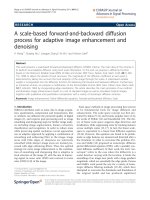
4th element 3rd element 2nd element 1st element
Figure 1: Antenna array model geometry.
N = T/T
c
. We assume, for simplicity, that T
g
equals T
c
.The
complex lowpass impulse response of the vector channel as-
sociated with the kth user may be written as [3]
h
k
(τ) =
L
(k)
−1
l=0
β
(k)
l
exp
jϕ
(k)
l
V
θ
(k)
l
δ
τ −τ
(k)
l
,(2)
where β
(k)
l
is the Rayleigh fading strength, ϕ
(k)
l
is its phase
shift, and τ
(k)
l
is the propagation delay. The kth user’s lth path
arrayresponsevectorisexpressedas
V
θ
(k)
l
=
1exp
−
j2πd cos θ
(k)
l
λ
···exp
−
j2(M−1)πdcos θ
(k)
l
λ
T
.
(3)
Throughout this paper, we consider that the array geometry,
which is the parameter of the antenna aperture gain, is a uni-
form linear array (ULA) of M identical sensors in Figure 1.
All signals from MS arrive at the BS AA with mean angle of
arrival (AOA) θ
(k)
l
which is uniformly distributed in [0, π).
Assuming Rayleigh fading, the probability density function
(pdf) of signal strength associated with the kth user’s lth
propagation path, l = 0, 1, , L
(k)
− 1, is presented as
p
β
(k)
l
=
2β
(k)
l
Ω
(k)
l
exp
−
β
(k)
l
2
Ω
(k)
l
,(4)
where Ω
(k)
l
is the second moment of β
(k)
l
with
∞
l=0
Ω
l
= 1,
and we assume it is related to the second moment of the ini-
tial path strength Ω
(k)
0
for exponentially decaying MIP as
Ω
(k)
l
= Ω
(k)
0
exp(−lδ), for 0 <l≤ L
(k)
− 1, δ ≥ 0, (5)
where δ reflects the rate at which the decay of average path
strength as a function of path delay occurs. Note that a more
realistic profile model may be the exponential MIP.
The receiver is a coherent RAKE receiver with AA, where
the number of fingers L
r
is a variable less than or equal to
L
(k)
which is the number of resolvable propagation paths as-
sociated with the kth user. Perfect estimates of the channel
A Combined Antenna Arrays and Reverse-Link Synchronous DS-CDMA System 1301
parameters are assumed. The complex received signal is ex-
pressed as
r(t) =
√
2P
K
k=1
λ
k
L
(k)
−1
l=0
β
(k)
l
V
θ
(k)
l
b
(k)
t −τ
(k)
l
× g
(k)
t − τ
(k)
l
a
t −τ
(k)
l
cos
ω
c
t + ψ
(k)
l
+ n(t),
(6)
where P is the average received power and ψ
(k)
l
is the phase
of the lth path associated to the kth carrier. λ
k
corresponds to
the PCE of the kth user which is a random variable due to im-
perfect power control [8]. We consider λ
k
to be log-normally
distributed with standard deviation σ
λ
k
dB. In other words,
λ
k
= 10
(x/10)
, where the variable x follows a normal distribu-
tion. n(t)isanM × 1 spatially and temporally white Gaus-
sian noise vector with a zero mean and covariance which is
given by E{n(t)n
H
(t)}=σ
2
n
I,whereI is the M × M iden-
tity matrix, σ
2
n
is the antenna noise variance with η
0
/2, and
the superscript H denotes the Hermitian-transpose operator.
When the received signal is matched to the reference user’s
code, the lth multipath matched filter output for the interest
user (k = 1) can be expressed as
y
(1)
l
=
τ
(1)
l
+T
τ
(1)
l
r(t) · g
(1)
t−τ
(1)
l
a
t−τ
(1)
l
cos
ω
c
t + ψ
(1)
l
dt
= S
(1)
l
+ I
(1)
l,mai
+ I
(1)
l,si
+ I
(1)
l,ni
.
(7)
When a reference signal is not available, a common crite-
rion for optimizing the weight vectors and this criterion is to
maximize the signal-to-interference plus noise ratio (SINR).
In ( 7), u
(1)
l
= I
(1)
l,si
+ I
(1)
l,mai
+ I
(1)
l,ni
is a total interference plus
noise for the lth path of interest user. By solving the follow-
ing problem, we can obtain the optimal weights to maximize
the SINR [9]:
W
(1)
l(opt)
= max
W=0
W
(1)
H
l
R
yy
W
(1)
l
W
(1)
H
l
R
uu
W
(1)
l
,(8)
where R
yy
and R
uu
are the second-order correlation matri-
ces of the received signal subspace and the interference plus
noise subspace, respectively. Here, R
uu
can be estimated by
the code-filtering approach in [2], which is presented as
R
uu
=
N
N − 1
R
rr
−
1
N
R
yy
,(9)
where R
rr
means the covariance matrix of the received sig-
nal prior to RAKE. The solution corresponds to the largest
eigenvalue (λ
max
) of the generalized eigenvalue problem in
the matrix pair (R
yy
, R
uu
). Therefore, we can obtain the max-
imum SINR when the weight vector W
(1)
l(opt)
equals the prin-
cipal eigenvector of the matrix pair, which is presented as
R
yy
· W
(1)
l(opt)
= λ
max
· R
uu
· W
(1)
l(opt)
. (10)
From (7)and(8), the corresponding beamformer output for
the lth path of interest user is
ˆ
z
(1)
l
= W
(1)
H
l
· y
(1)
l
=
ˆ
S
(1)
l
+
ˆ
I
(1)
l,mai
+
ˆ
I
(1)
l,si
+
ˆ
I
(1)
l,ni
,
(11)
where
ˆ
S
(1)
l
=
Pλ
1
/2β
(1)
l
C
(1,1)
ll
b
(1)
0
T,
ˆ
I
(1)
l,mai
=
P/2
K
k=2
λ
k
L
(k)
−1
j=0
β
(k)
j
C
(l,k)
lj
×
b
(k)
−1
RW
k1
τ
(k)
lj
+ b
(k)
0
RW
k1
τ
(k)
lj
cos
Ψ
(k)
lj
,
ˆ
I
(1)
l,si
=
Pλ
1
/2
L
(1)
−1
j=0
j=l
β
(1)
j
C
(1,1)
lj
b
(1)
−1
RW
11
τ
(1)
lj
+ b
(1)
0
RW
11
τ
(1)
lj
cos
Ψ
(1)
lj
,
ˆ
I
(1)
l,ni
=
τ
(1)
l
+T
τ
(1)
l
W
(1)
H
l
·n(t)g
(1)
t −τ
(1)
l
× a
t −τ
(1)
l
cos
ω
c
t + ψ
(1)
l
dt,
(12)
with b
(1)
0
being the information bit to be detected, b
(1)
−1
the
preceding bit, τ
(k)
lj
= τ
(k)
j
− τ
(1)
l
,andψ
(k)
lj
= ψ
(k)
j
− ψ
(1)
l
.
W
(1)
l
= [w
(1)
l,1
w
(1)
l,2
···w
(1)
l,M
]
T
is the M × 1weightvectorfor
the lth path of the first user. C
(1,k)
lj
= W
(1)
H
l
· V(θ
(k)
j
)rep-
resents the spatial correlation between the array response
vector of the kth user at the jth multipath and the weight
vector of the interest user at the lth path. RW and
RW are
Walsh-PN continuous partial cross-correlation functions de-
fined by RW
k1
(τ) =
τ
0
g
(k)
(t − τ)a(t − τ) · g
(1)
(t)a(t)dt and
RW
k1
(τ) =
T
τ
g
(k)
(t − τ)a(t − τ)g
(1)
(t)a(t)dt.From(11),
we can obtain the Rake receiver output from MRC combin-
ing
ˆ
z
(1)
=
L
r
l=0
β
(1)
l
·
ˆ
z
(1)
l
and see that the outputs of the lth
branch, l = 0, 1, , L
r
− 1, consist of four terms. The first
term represents the desired signal component to be detected.
The second term represents the MAI from (K − 1) other si-
multaneous users in the system. The third term is the self-
interference (SI) for the reference user. Finally, the last term
is AWGN.
3. PERFORMANCE OF AA WITH RLSTT IN RAYLEIGH
FADING CHANNEL WITH PCE
In our analysis, the evaluation is carried out for the case in
which the arrival time of paths is modeled as synchronous in
the first branch (i.e., for main paths) but as asynchronous in
the rest of the branches (i.e., for multipaths). With the well-
known Gaussian approximation, we model the MAI terms in
the first branch and the other branches as a Gaussian process
with variances equal to the MAI variances for l = 0andfor
l ≥ 1, respectively. Extending the derived results in [7], the
1302 EURASIP Journal on Applied Signal Processing
variance of MAI for l = 0, conditioned on the values of β
(1)
l
and λ
k
,is
σ
2
mai,0
=
E
b
T(2N − 3)
12N(N − 1)
β
(1)
0
2
K
k=2
λ
k
L
(k)
−1
j=1
Ω
(k)
j
ζ
(1,k)
2
0 j
. (13)
Similarly, the variance of MAI for l ≥ 1is
σ
2
mai,l
=
E
b
T(N − 1)
6N
2
β
(1)
l
2
K
k=2
λ
k
L
(k)
−1
j=0
Ω
(k)
j
ζ
(1,k)
2
lj
, (14)
where E
b
= PT is the signal energy per bit, and ζ
(1,k)
2
lj
=
E{C
(1,k)
lj
}
2
is the second-order char acterization of the spa-
tial correlation between the array response vector of the kth
user at the jth multipath and the weight vector of interest
user at the lth path, of which more detailed derivation is de-
scribed in the appendix. The conditional variance of σ
2
si,l
is
approximated by [10]:
σ
2
si,l
≈
E
b
λ
1
T
4N
β
(1)
l
2
L
(1)
−1
j=0
j=l
Ω
(1)
j
ζ
(1,1)
2
lj
. (15)
The variance of the AWGN term, conditioned on the value of
β
(1)
l
, is calculated as
σ
2
ni,l
=
Tη
0
ζ
(1,1)
2
ll
4M
·
β
(1)
l
2
. (16)
Therefore, the output of the receiver is a Gaussian random
process with mean
U
s
=
E
b
λ
1
T
2
L
r
−1
l=0
β
(1)
l
2
ζ
(1,1)
ll
(17)
and the total variance equal to the sum of the variance of all
the interference and noise terms. From (13), (14), (15), and
(16), we have
σ
2
T
= σ
2
mai,0
+
L
r
−1
l=1
σ
2
mai,l
+
L
r
−1
l=0
σ
2
si,l
+ σ
2
ni,l
= E
b
TΩ
0
×
(2N − 3)
q
L
r
, δ
− 1
λ
I
ζ
2
0
·
β
(1)
0
2
12N(N − 1)
+
(N − 1)q
L
r
, δ
λ
I
ζ
2
·
L
r
−1
l=1
β
(1)
l
2
6N
2
+
λ
1
q
L
r
, δ
−1
ζ
2
0
·
β
(1)
0
2
+ζ
2
·
L
r
−1
l=1
β
(1)
l
2
4N
+
η
0
ζ
2
0
·
β
(1)
0
2
+ ζ
2
·
L
r
−1
l=1
β
(1)
l
2
4ME
b
Ω
0
.
(18)
At the output of the receiver, SNR may be written in a more
compact form as γ
s
:
γ
s
=
(2N −3)
q
L
r
, δ
−1
λ
I
6N(N − 1)
·
ζ
2
0
·
β
(1)
0
2
ζ
0
·
β
(1)
0
2
+ ζ
·
L
r
−1
l=1
β
(1)
l
2
+
(N − 1)q
L
r
, δ
λ
I
3N
2
·
ζ
2
·
L
r
−1
l=1
β
(1)
l
2
ζ
0
·
β
(1)
0
2
+ζ
·
L
r
−1
l=1
β
(1)
l
2
+
q
L
r
, δ
− 1
λ
1
2N
·
ζ
2
0
·
β
(1)
0
2
+ ζ
2
·
L
r
−1
l=1
β
(1)
l
2
ζ
0
·
β
(1)
0
2
+ ζ
·
L
r
−1
l=1
β
(1)
l
2
+
η
0
2MΩ
0
E
b
·
ζ
2
0
·
β
(1)
0
2
+ ζ
2
·
L
r
−1
l=1
β
(1)
l
2
ζ
0
·
β
(1)
0
2
+ ζ
·
L
r
−1
l=1
β
(1)
l
2
−1
×
λ
1
ζ
0
·
β
(1)
0
2
+ ζ
·
L
r
−1
l=1
β
(1)
l
2
Ω
0
,
(19)
where q(L
r
, δ) =
L
r
−1
l
=0
exp(−lδ) = 1 − exp(−L
r
δ)/1 −
exp(−δ), λ
I
=
K
k=2
λ
k
,andΩ
(k)
0
= Ω
0
. ζ
(k,m)
2
lj
= ζ
2
0
when
k = m or l = j for l = 0, ζ
(k,m)
2
lj
= ζ
2
when k = m or l = j
for l>0, ζ
(k,m)
2
lj
= ζ
2
0
when k = m and l = j for l = 0, and
ζ
(k,m)
2
lj
= ζ
2
when k = m and l = j for l>0. In [11], the pdf
of λ
I
=
K
k=2
λ
k
for K − 1 users is an approximately lognor-
mal distribution, with the following logarithmic mean and
variance, which is presented as
p
λ
I
=
1
√
2πσ
λ
I
λ
I
exp
−
ln λ
I
− m
λ
I
2
2σ
2
λ
I
, (20)
where
σ
2
I
= ln
1
K − 1
exp
σ
2
λ
I
+
K
−2
K − 1
,
m
I
= ln(K − 1) + m +
σ
2
λ
I
2
−
1
2
ln
K − 2
K − 1
+
1
K − 1
exp
σ
2
λ
I
.
(21)
This method is valid for a logarithmic standard deviation σ
λ
less than 4 dB. To evaluate the average bit er ror probability,
P
l
e
(λ
1
, λ
I
), conditioning on the values of λ
1
and λ
I
follows as
P
l
e
λ
1
, λ
I
=
∞
0
∞
0
Q
γ
s
L
r
−1
k=1
π
k
Ω
k
exp
−x/Ω
k
·
1
Ω
0
exp
−y/Ω
0
dx dy,
(22)
where π
k
= Π
L
r
−1
i=1,i=k
(x
k
/(x
k
−x
i
)) = Π
L
r
−1
i=1,i=k
(Ω
k
/(Ω
k
−Ω
i
)),
Q(x) = (1/
√
2π)
∞
x
exp(−u
2
/2)du. The average bit error
A Combined Antenna Arrays and Reverse-Link Synchronous DS-CDMA System 1303
10
−1
10
−2
10
−3
10
−4
10
−5
BER
0 5 10 15 20
E
b
/N
0
(dB)
Sync, PCE = 0 dB (analysis)
Async, PCE = 0 dB (analysis)
Sync, PCE = 0 dB (simulation)
Async, PCE = 0 dB (simulation)
Sync, PCE = 3 dB (analysis)
Async, PCE = 3 dB (analysis)
Sync, PCE = 3 dB (simulation)
Async, PCE = 3 dB (simulation)
(a)
10
−1
10
−2
10
−3
10
−4
10
−5
BER
0 5 10 15 20
E
b
/N
0
(dB)
Sync, PCE = 0 dB (analysis)
Async, PCE = 0 dB (analysis)
Sync, PCE = 0 dB (simulation)
Async, PCE = 0 dB (simulation)
Sync, PCE = 3 dB (analysis)
Async, PCE = 3 dB (analysis)
Sync, PCE = 3 dB (simulation)
Async, PCE = 3 dB (simulation)
(b)
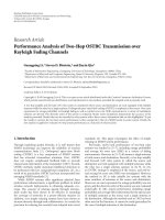
Figure 2: Analytical results versus simulation results. (Number of users = 12, M = 4, L
r
= L
(k)
= 2, PCE = 0and3dB.)(a)δ = 1.0, (b)
δ = 0.2.
probability P
e
is calculated as
P
e
=
1
√
π
∞
−∞
1
√
π
∞
−∞
P
l
e
exp
√
2σ
λ
1
z
1
+ m
λ
1
,
exp
√
2σ
λ
I
z
I
+ m
λ
I
× exp
− z
2
1
dz
1
exp
− z
2
I
dz
I
,
(23)
where z
1
= (ln λ
1
−m
λ
1
)/
√
2σ
λ
1
and z
I
= (ln λ
I
−m
λ
I
)/
√
2σ
λ
I
.
This integration can be easily obtained by using the Hermite
polynomial approach, which requires only summation and
no integration [12]:
P
e
=
1
π
h
l=1
w
l
h
n=1
w
n
P
l
e
exp
√
2σ
λ
1
x
n
+ m
λ
1
,
exp
√
2σ
λ
I
x
l
+ m
λ
I
.
(24)
4. NUMERICAL RESULTS
In this section, we have investigated the user capacity of AA
system both with RLSTT and without RLSTT, considering
several important factors such as the shape of MIP, the num-
ber of antennas, and the PCE. In all evaluations, processing
gain is assumed to be 128, and the number of paths and taps
in RAKE is assumed to be the same for all users and denoted
by two. The decaying factor is considered as 1.0 or 0.2 for
the exponential MIP. The sensor spacing is half of the carr ier
wavelength.
Figure 2 shows uncoded BER performance as a function
of E
b
/N
0
, when the number of users is twelve and the number
of antennas is four in the exponential MIP. Two decay factors
are considered, and both perfect power control (PCE = 0dB)
and imperfect power control (PCE = 3 dB) are assumed. The
results confirm that the analytical results are well matched
to the simulation results. It is noted that using RLSTT to-
gether with AA may enhance the performance, since RLSTT
tends to make better the estimation of covariance matrices
for beamformer-RAKE rec eiver.
The BER curves are plotted as functions of the number
of users in Figure 3 when E
b
/N
0
= 20dB and power con-
trol is perfect. The number of antennas is chosen among
one, four, or eight. It is shown that AA with RLSTT demon-
strates significant performance gain when the number of
users increases, even though the performance improvement
decreases when the number of antenna increases. For exam-
ple, in the case of four antennas, while AA without RLSTT
supports 60 users, AA with RLSTT supports more than 96
users at a BER of 10
−3
, showing an enhancement of 50%.
Figure 4 shows the BER system performance as a func-
tion of the number of users, when M = 4, E
b
/N
0
= 20 dB,
1304 EURASIP Journal on Applied Signal Processing
10
−1
10
−2
10
−3
10
−4
10
−5
10
−6
BER
12 24 36 48 60 72 84 96
Number of users
with RLSTT
without RLSTT
M = 1
M = 4
M = 8
(a)
10
−1
10
−2
10
−3
10
−4
10
−5
10
−6
BER
12 24 36 48 60 72 84 96
Number of users
with RLSTT
without RLSTT
M = 1
M = 4
M = 8
(b)
Figure 3: BER versus number of users in AA with RLSTT and AA without RLSTT (E
b
/N
0
= 20 dB, M = 1, 4,and 8, L
r
= L
(k)
= 2,
PCE = 0dB).(a)δ = 1.0, (b) δ = 0.2.
10
−2
10
−3
10
−4
10
−5
BER
12 24 36 48 60 72 84
Number of users
with RLSTT
without RLSTT
PCE = 0dB
PCE = 1dB
PCE = 2dB
PCE = 3dB
PCE = 4dB
(a)
10
−2
10
−3
10
−4
10
−5
BER
12 24 36 48 60 72 84
Number of users
with RLSTT
without RLSTT
PCE = 0dB
PCE = 1dB
PCE = 2dB
PCE = 3dB
PCE = 4dB
(b)
Figure 4: BER versus number of users in AA with RLSTT and AA without RLSTT (E
b
/N
0
= 20 dB, M = 4, L
r
= L
(k)
= 2, PCE =
0, 1, 2,3, and 4 dB). (a) δ = 1.0, (b) δ = 0.2.
and power control is imperfect. The curves are parameter-
ized by different PCE values such as PCE = 0, 1, 2, 3, and
4[dB], and show that RLSTT makes DS-CDMA system with
AA insensitive to the PCE and thus increases the achievable
overall system capacity. At BER = 5 × 10
−4
,AAwithRLSTT
when PCE = 2 dB can support even greater number of users,
about 35% more than AA without RLSTT when power con-
trol is perfect (PCE = 0 dB), even though its capacity when
PCE = 2 dB is degraded about 28% in comparison to the
perfect power control.
A Combined Antenna Arrays and Reverse-Link Synchronous DS-CDMA System 1305
100
90
80
70
60
50
40
30
20
10
0
Number of users
0123
PCE (dB)
with RLSTT
without RLSTT
M = 4
M = 8
(a)
90
80
70
60
50
40
30
20
10
0
Number of users
0123
PCE (dB)
with RLSTT
without RLSTT
M
= 4
M = 8
(b)
Figure 5: Number of users versus PCE in AA with RLSTT and AA without RLSTT (E
b
/N
0
= 20 dB, M = 4and8,L
r
= L
(k)
= 2, BER = 10
−4
)
(a) δ = 1.0(b)δ = 0.2.
In Figure 5, the maximum allowable number of users to
achieve BER of 10
−4
is shown as a function of PCE when
the number of antenna elements is four or eight. The fig-
ure demonstrates while in eight-element AA without RLSTT
PCEisrequiredtokeeplessthan1dBinordertoachievethe
user capacity of 50 users, AA with RLSTT may make loose
the requirement to 3 dB. The figure can also be used to find
the overall system capacity for a given PCE and the num-
ber of antenna elements. These results, however, do not take
into account effects such as coding and interleaving. Addi-
tionally, it is apparent that RLSTT has superior performance
and/or reduces the complexity of the system since AA with
RLSTT with fewer numbers of antennas can obtain better
performance than AA without RLSTT.
5. CONCLUSIONS
In this paper, we presented an improved AA, in which RLSTT
is incorporated to effectively make better an estimation of co-
variance matrices at a beamformer-RAKE receiver, and inves-
tigated the user capacity and the performance analysis which
reflects several important fac tors such as the shape of mul-
tipath intensity profile (MIP), the number of antennas, and
power control error (PCE). The results show that the orthog-
onality provided by employing RLSTT along with AA may
make the DS-CDMA system insensitive to the PCE even with
fewer numbers of antennas. Additionally, RLSTT has supe-
rior performance and/or reduces the complexity of the sys-
tem since AA with RLSTT with fewer numbers of antennas
can obtain better p erformance than AA without RLSTT. The
consideration of estimation technique such as diagonal load-
ing employed in the proposed system may be an interesting
issue for future study.
APPENDIX
SPATIAL CORRELATION STATISTICS
From (10), we can obtain the optimal beamformer weight
presented as
W
(k)
l
= ξ · R
(k)
−1
uu,l
V
θ
(k)
l
;(A.1)
since ξ does n ot affect the SINR, we can set ξ = 1. When
the total number of paths is large, a large code length yields
R
(k)
uu,l
= σ
(k)
2
s,l
·I [2]. However, it means that the total undesired
signal vector can be modeled as a spatially white Gaussian
random vector. Here, σ
(k)
2
s,l
is the total interference-plus-noise
power. From (7), the total interference-plus-noise for the lth
path of the kth user in the matched filter output is shown as
u
(k)
l
= I
(k)
l,si
+ I
(k)
l,mai
+ I
(k)
l,ni
. (A.2)
If we assume that the angles of arrival of the multipath com-
ponents are uniformly distributed over [0, π), the total inter-
ference vector I
(k)
l,si
+ I
(k)
l,mai
will be spatially white [2,Chapter
6]. In this case, the variance of the undesired signal vector is
calculated as
E
u
(k)
l
· u
(k)
H
l
= σ
(k)
2
s,l
· I
=
σ
(k)
2
mai,l
+ σ
(k)
2
si,l
+ σ
(k)
2
ni,l
· I,
(A.3)
where σ
(k)
2
mai,l
and σ
(k)
2
si,l
are the noise v ariance of MAI and SI in
one-dimension antenna system. For the RLSTT model [7],
all active users are synchronous in the first branch. Therefore,
1306 EURASIP Journal on Applied Signal Processing
we can obtain the different variance of the total interference-
plus-noise for l = 0andforl ≥ 1, conditions on the value of
λ
k
, respectively, expressed as follows:
σ
(k)
2
s,0
λ
1
, λ
I
= E
b
TΩ
0
(2N − 3)λ
I
q
L
r
, δ
− 1
12N(N − 1)
+
λ
1
q
L
r
, δ
− 1
4N
+
η
0
4E
b
Ω
0
for l = 0,
σ
(k)
2
s,l
λ
1
, λ
I
= E
b
TΩ
0
(N − 1)λ
I
q
L
r
, δ
6N
2
+
λ
1
q
L
r
, δ
− 1
4N
+
η
0
4E
b
Ω
0
for l ≥ 1.
(A.4)
Using the Hermite polynomial approach, we can evaluate the
average total interference-plus-noise power per AA element.
With these assumptions, the optimal beamformer weight
of the kth user at the lth multipath can be shown to be
W
(k)
l
= σ
(k)
−2
s,l
·V(θ
(k)
l
). Therefore, between the array response
vector of the mth user at the hth multipath and the weight
vector of the kth user’s lth path, the spatial correlation can be
expressed as
C
(k,m)
lh
=
V
H
θ
(k)
l
V
θ
(m)
h
σ
(k)
2
s,l
=
CR
(k,m)
lh
σ
(k)
2
s,l
,(A.5)
where
CR
(k,m)
lh
=
M−1
i=0
exp
jπ sicos
θ
(k)
l
exp
− jπ si cos
θ
(m)
h
,
s =
2d
λ
.
(A.6)
The second-order characterization of the spatial correla-
tion is calculated as
ζ
(k,m)
2
lh
= E
C
(k,m)
lh
2
=
E
CR
(k,m)
lh
2
σ
(k)
4
s,l
,(A.7)
where
CR
(k,m)
lh
2
= A
θ
(k)
l
, θ
(m)
h
=
M−1
i=0
(i +1)exp
jπ sicos θ
(k)
l
exp
− jπ si cos θ
(m)
h
+
2(M−1)
i=M
(2M − i − 1) exp
jπ sicos θ
(k)
l
× exp
− jπ si cos θ
(m)
h
.
(A.8)
Themeananglesofarrivalθ
(k)
l
and θ
(m)
h
have uniform distri-
bution in [0, π) independently. So,
E
CR
(k,m)
lh
2
=
π
0
π
0
A
θ
(k)
l
, θ
(m)
h
dθ
(k)
l
dθ
(m)
h
=
M−1
i=0
(i +1)J
0
(π si)J
0
(−π si)
+
2(M−1)
i=M
(2M − i − 1)J
0
(π si)J
0
(−π si), k = m or l = h,
M
2
, k =m, l=h,
(A.9)
where J
0
(x) is the zero-order Bessel function of the first
kind.
REFERENCES
[1] L. C. Godara, “Application of antenna arrays to mobile com-
munications. II. Beam-forming and direction-of-arrival con-
siderations,” Proceedings of the IEEE, vol. 85, no. 8, pp. 1195–
1245, 1997.
[2] A.F.Naguib, Adaptive antennas for CDMA wireless networks ,
Ph.D. dissertation, Electrical Engineering Department, Stan-
ford University, Stanford, Calif, USA, 1996.
[3] G. Raleigh, S. N. Diggavi, A. F. Naguib, and A. Paulraj, “Char-
acterization of fast fading vector channels for multi-antenna
communication systems,” in Proc. 28th Asilomar Conference
on Signals, Systems and Computers, vol. 2, pp. 853–857, Pacific
Grove, Calif, USA, October–November 1994.
[4] A. Stephenne and B. Champagne, “Effective multi-path vector
channel simulator for antenna array systems,” IEEE Trans.
Vehicular Technology, vol. 49, no. 6, pp. 2370–2381, 2000.
[5] J. S. Thompson, P. M. Grant, and B. Mulgrew, “Smart antenna
arrays for CDMA systems,” IEEE Personal Communications,
vol. 3, no. 5, pp. 16–25, 1996.
[6] A. J. Paulraj and C. B. Papadias, “Space-time processing for
wireless communications,” IEEE Signal Processing Magazine,
vol. 14, no. 6, pp. 49–83, 1997.
[7] E K. Hong, S H. Hwang, K J. Kim, and K C. Whang, “Syn-
chronous transmission technique for the reverse link in DS-
CDMA terrestrial mobile systems,” IEEE Trans. Communica-
tions, vol. 47, no. 11, pp. 1632–1635, 1999.
[8] W. Ye and A. M. Haimovich, “Performance of cellular CDMA
with cell site antenna arrays, Rayleigh fading, and power con-
trol error,” IEEE Trans. Communications,vol.48,no.7,pp.
1151–1159, 2000.
[9] J. Litva and T K. Lo, Digital Beamforming in Wireless Commu-
nications, Artech House Publisher, Boston, Mass, USA, 1996.
[10] T. Eng and L. B. Milstein, “Coherent DS-CDMA performance
in Nakagami multipath fading,” IEEE Trans. Communications,
vol. 43, no. 234, pp. 1134–1143, 1995.
[11] R. Prasad, CDMA for Wireless Personal Communications,
Artech House Publisher, Boston, Mass, USA, 1996.
[12] M.AbramowitzandI.A.Stegun, Handbook of Mathematical
Functions, National Bureau of Standards Applied Mathemat-
ics Series, Dover Publications, New York, NY, USA, 1965.
A Combined Antenna Arrays and Reverse-Link Synchronous DS-CDMA System 1307
Yong-Seok Kim was born August, 1970, in
Seoul, Korea. He received the B.S. degree in
electronic engineering from the Kyung Hee
University, Yongin-shi, Korea, in 1998, and
the M.S. degree in electrical and computer
engineering from Yonsei University, Seoul,
Korea, in 2000, and is working toward the
Ph.D. degree in electrical and electronic en-
gineering at the same university. His cur-
rent research interests include multiple an-
tenna system, multiuser communication, multicarrier system, and
4G communication techniques.
Seung-Hoon Hwang received t he B.S. d e-
gree in electrical engineering and the M.S.
and Ph.D. degrees in communication sys-
tems from Yonsei University, Seoul, Korea
in 1992, 1994, and 1999, respectively. His
Ph.D. thesis is entitled “Performance eval-
uation of a synchronous DS-CDMA sys-
tem in a mobile radio channel.” From 1999
to 2003, he had worked for LG Electronics
where he was a Chief Research Engineer in
UMTS System Laboratory, LG R&D Center, participating in IMT-
2000 physical layer standardization activities. From 2003, he is a
Visiting Research Fellow at the School of Electronics and Com-
puter Science in the University of Southampton, UK. His current
research interests include interference cancellation techniques for
DS-CDMA and various aspects of wideband/broadband CDMA.
Dr. Hwang is a recipient of the British Chevening Scholarship
awarded by the British Council, UK.
Hyo-Yol Park was born October, 1977, in
Seoul, Korea. He received the B.S. degree in
electronic engineering from the Yonsei Uni-
versity, Seoul, Korea, in 2000, and the M.S.
degree in electrical and electronic engineer-
ing from Yonsei University, Seoul, Korea, in
2002, and is working toward the Ph.D. de-
gree in electrical and elect ronic engineering
at the same university. His current research
interests include space-time coding, hybrid
ARQ, turbo coding, multicarrier system, and 4G communication
techniques.
Keum-Chan Whang was born on July 18,
1944, in Seoul, Korea. He received the B.S.
degree in electrical engineering from Yon-
sei University, Seoul, Korea, in 1967, and the
M.S. and Ph.D. degrees from the Polytech-
nic Institute of New York, in 1975 and 1979,
respectively. From 1979 to 1980, he was a
Member of Research Staff at the Agency for
Defense Development, Korea. Since 1980,
he has been Professor of the Department of
Electrical and Electronic Engineering, Yonsei University. For the
government, he performed various duties such as being a Mem-
ber of Radio Wave Application Committee, a Member of Korea
Information & Communication Standardization Committee, and
is an Advisor for the Ministry of Information and Communica-
tion’s technology fund and a Director of Accreditation Board for
Engineering Education of Korea. Currently, he serves as a Mem-
ber of Korea Communications Commission, a Project Manager of
Qualcomm-Yonsei Research Lab, and a Director of Yonsei’s IT Re-
search Center. His research interests include spread-spectrum sys-
tems, multiuser communications, and 4G communications tech-
niques.