Báo cáo hóa học: " Filter-Bank-Based Narrowband Interference Detection and Suppression in Spread Spectrum Systems" pptx
Bạn đang xem bản rút gọn của tài liệu. Xem và tải ngay bản đầy đủ của tài liệu tại đây (796 KB, 14 trang )
EURASIP Journal on Applied Signal Processing 2004:8, 1163–1176
c
2004 Hindawi Publishing Corporation
Filter-Bank-Based Narrowband Interference Detection
and Suppression in Spread Spectrum Systems
Tobias Hidalgo Stitz
Institute of Communications Engineering, Tampere University of Technology, P.O. Box 553, 33101 Tampere, Finland
Email: tobias.hidalgo@tut.fi
Markku Renfors
Institute of Communications Engineering, Tampere University of Technology, P.O. Box 553, 33101 Tampere, Finland
Email: markku.renfors@tut.fi
Received 29 October 2002; Revised 27 October 2003; Recommended for Publication by Xiang-Gen Xia
A filter-bank-based narrowband interference detection and suppression method is developed and its performance is studied in
a spread spectrum system. The use of an efficient, complex, critically decimated perfect reconstruction filter bank with a highly
selective subband filter prototype, in combination with a newly developed excision algorithm, offers a solution with efficient
implementation and performance close to the theoretical limit derived as a function of the filter bank stopband attenuation. Also
methods to cope with the transient effects in case of frequency hopping interference are developed and the resulting performance
shows only minor degradation in comparison to the stationary case.
Keywords and phrases: narrowband interference cancellation, complex PR filter banks, DS-SS.
1. INTRODUCTION
Direct sequence spread spectrum (DS-SS) systems have sev-
eral applications, for example, CDMA communications and
advantages, low power spectral density, privacy of the com-
munications, and an inherent immunity to narrowband in-
terferences, due to the processing gain [1]. Nevertheless,
this immunity is only effective up to certain interference
power, making it necessary to apply additional techniques
to suppress the effect of strong narrowband interferences
if a degradation of the performance is to be avoided. Sev-
eral interference suppression techniques have been pro-
posed to process the signal in the time domain (e.g., adap-
tive transversal fi ltering) [2, 3, 4, 5, 6] and in the trans-
form domain [2, 7, 8, 9].Thesetechniquestakeadvan-
tage of the knowledge of the wide spectral shape of the de-
sired signal’s spectrum as compared to the interferer’s nar-
row spectrum. There are also methods in the spatial do-
main, using techniques like antenna diversity or beamform-
ing [2, 10], although these methods are not exclusive to nar-
rowband interference on a wideband SS signal. There ex-
ist more advanced approaches in the time-frequency do-
main [11, 12], like wavelet transformation-based methods.
In situations in which the interfering environment changes
quickly, time-domain techniques are too slow to work cor-
rectly. In these cases, frequency-domain techniques like the
FFT-based or the filter-bank-based methods perform better
[8, 12].
The purpose of this paper is to analyse the performance
of a filter-bank-based interference suppression system. To
eliminate the effects of narrowband interference, a perfect
reconstruction (PR) filter bank with interference detection
and subband suppression logic is used. Efficient implemen-
tation of the complex, critically sampled filter bank is based
on an extension of the extended lapped transform (ELT)
to the complex case. Based on detection and excision algo-
rithms that can be found in the literature [8],anew,im-
proved recursive algorithm is developed. Simulations have
been run with different types of narrowband interference
sources (jammers), demonstrating promising performance
even in high jammer power cases.
The structure of the paper is as follows. Section 2 intro-
duces the idea of filter-bank-based interference suppression
and proposes an efficient implementation for the filter bank.
Also the novel excision algorithm is presented and meth-
ods to relieve the transient effects in case of frequency hop-
ping interference are introduced. Section 3 presents a the-
oretical performance analysis of the system. In Section 4 a
detailed system model is presented and performance simu-
lation results are shown and discussed in Section 5. Finally,
Section 6 summarizes the conclusions obtained from this re-
search work.
1164 EURASIP Journal on Applied Signal Processing
f
0
|H(w)|
(a)
f
π
0
|H(w)|
M − 1
···102M − 12M − 2···
(b)
Figure 1: Modulated filter bank. (a) Prototy pe filter. (b) Complex
modulated subband filters.
F
2M−1
(z)2M
Y
2M−1
(z)
2MH
2M−1
(z)
ˆ
X
(z)
+
.
.
.
.
.
.
X(z)
F
1
(z)2M
Y
1
(z)
2MH
1
(z)
F
0
(z)2M
Y
0
(z)
2MH
0
(z)
Figure 2: Maximally decimated 2M-channel analysis-synthesis fil-
ter bank system.
2. FILTER BANKS FOR INTERFERENCE SUPPRESSION
2.1. Detection and suppression principle
The interference suppressor presented in this paper is based
on a complex modulated filter bank (MFB). In a complex
MFB,aprototypefilterh
p
(n) is modulated by a complex ex-
ponential function to yield 2M bandpass filters in the form
h
k
(n) = h
p
(n) · e
jn(2k+1)π/2M
. (1)
As shown in Figure 1, the whole sampled frequency range can
be divided into subbands by lining up consecutive filters. In
the following, the terms “subchannel” and “subband” will be
used interchangeably.
MFBs can be used to form analysis-synthesis filter banks
that divide the received signal into several subchannels (anal-
ysis part), and reconstruct the original signal from the sub-
channels (synthesis part), after some optional processing.
One benefit of this type of filter banks is that the process-
ing can be done at a lower sampling rate, taking advantage
f
f
rd
f
sp
f
Figure 3: Application of the filter bank to the elimination of nar-
rowband interference.
of the reduced bandwidth due to the subband filtering [13].
Figure 2 presents a maximally decimated filter bank, which
means that, if the filter bank consists of 2M channels, the
factor by which the down- and upsampling is performed is
also 2M.
If the filter design parameters are chosen correctly, the
filter bank can offer PR, meaning that the output signal is
just a scaled and delayed version of the input signal [13]:
ˆ
x(n) = cx
n − n
0
. (2)
Applying the filter banks to the narrowband interference sup-
pression problem, the subbands affected by the interference
are not included in the synthesis part of the filter, resulting in
notch filtering, as sketched in Figure 3 [2, 12].
Since the FFT can also be regarded as a filter bank, it can
be used as an approach to remove the interference. However,
each subchannel of the FFT filter bank has strong sidelobes,
the first ones at −13 dB. Thus, the power of the narrowband
jammer is very likely to leak to adjacent subchannels, affect-
ing a relatively high portion of the signal bandwidth. To fight
this limitation, windowing can be applied to the signal be-
fore taking the FFT [14]. Although this is an effective solu-
tion to lower the sidelobes, the conditions for sufficient alias-
ing cancellation in an efficient, maximally decimated system
are not so well understood as in PR filter bank systems. It
should also be emphasized that a straightforward applica-
tion of the complex modulation principle does not provide
a PR system in the maximally decimated case [15]. Our im-
plementation of the filter bank overcomes these problems by
using the novel maximally decimated filter bank structure
[16] shown in Figure 4, based on the ELT [17]. Using a PR
filter bank, we also assure that the signal does not suffer any
additional distortion by the processing. This is especial ly im-
portant in the case in which there is no interference present
and no subband processing takes place. Further, the PR fil-
ter banks have efficient implementation methods based on
ELT that are not applicable in the non-PR case [18]. How-
ever, properly designed nearly-perfect-reconstruction (NPR)
CMFB/SMFB filter banks can be used in the same configura-
tion (Figure 4) to implement a complex NPR filter bank suit-
able for our application. Depending on the used hardware
architecture and allowed p erformance degradation in the in-
terference free case, such a design could be slightly more effi-
cient than the PR bank.
Filter-Bank-Based Interference Suppression 1165
M
Synthesis:
sine
modulated
filter bank
M
ˆ
Q
M
M
Synthesis:
cosine
modulated
filter bank
M
ˆ
I
M
.
.
.
.
.
.
2s
0
+
−
2c
0
+
M
Processing
2M − 2
2M − 1
M − 1
Processing
1
0
.
.
.
.
.
.
c
0
− s
0
+
−
s
0
c
0
+ s
0
+
c
0
M
Analysis:
sine
modulated
filter bank
MQ
M
M
Analysis:
cosine
modulated
filter bank
M
I
M
Figure 4: Realisation of the 2M-channel complex MFB using sine and cosine MFBs that can be implemented with real-valued ELTs.
2.2. Complex critically sampled PR
filter bank structure
Some papers have appeared proposing complex modulated
lapped transforms for different applications, such as audio
processing [19] and image motion estimation [20]. However,
these papers use real-valued input signals to which the trans-
form is applied.
The method chosen here to implement the complex MFB
for the interference detection and suppression system with
complex (I/Q) input signal is illustrated in Figure 4. The in-
puts are the real (I, in-phase) and imaginary (Q, quadrature)
parts of the complex signals. The P R cosine and sine MFBs
and the following butterfly structures effectively allow ob-
taining real subband signals by separating the positive and
negative parts of the spectrum corresponding to each real
subband, as sketched in Figure 5. If we observe the subsam-
pled signals of Figure 4, we can see that, due to the butterfly
structures, at the entrance of the synthesis banks we have, for
the kth subchannel in the upper branch (CMFB),
c
k
+ s
k
+
c
k
− s
k
= 2c
k
,(3)
and, in the lower branch (SMFB),
c
k
+ s
k
−
c
k
− s
k
= 2s
k
,(4)
where c
k
and s
k
are the outputs of the analysis CMFB and
SMFB for subchannel k, respectively (time index omitted).
From the point of view of the filter bank, the signal remains
unchanged (except for a scaling factor of 2), but in between
the butterflies, the positive and negative sides of the spectra
of the original signal at the entrance of the filter bank are sep-
arated. We can see this process in Figure 5. At the beginning
we have a complex signal with different positive and nega-
tive frequency spectra. A certain spectral region and its cor-
responding symmetric neg ative counterpart are highlighted
for better understanding. Next, the real and imag inary parts
of the complex signal are separated and their corresponding
spectra are shown. We then apply the filter bank and follow
the changes suffered by the highlighted sections of the spec-
trum, sections that for simplicity coincide with the kth sub-
channel of the filter bank. The real part of the signal is filtered
by the CMFB and the imaginary by the SMFB and then dec-
imated and combined by the first butterfly. This is reflected
in the spectra of Figure 5 by the spectral expansion inher-
ent to decimation and by the fact that in the upper branch
(c
k
+ s
k
) we now have a signal corresponding to the positive
side of the filtered spectrum section of the original signal x.
In a same manner, the lower branch (c
k
− s
k
) carries a signal
corresponding to the negative side of the filtered spectrum
section of the original signal x. Ignoring the processing stage,
1166 EURASIP Journal on Applied Signal Processing
f
ˆ
Q
−
SMFBCMFB
f
ˆ
I
+
2nd butterfly,
interpolation,
filtering, and
recombination
Processing
f
c
k
− s
k
−
f
c
k
+ s
k
+
Analysis filtering,
decimation, and 1st
butterfly
f
SMFB
Q = Im[x]
f
CMFB
I = Re[x]
f
x ∈ C
Figure 5: Separating and combining the spectral components using the structure of Figure 4.
after the second butterfly we recover the signals as they were
before the first one (except for the scaling factor). Upsam-
pling (spectral contraction) and recombining with the other
subband signals yields
ˆ
Iand
ˆ
Q, similar to I and Q, assuming
there was no further processing of the signals involved.
In other words, the analysis subchannel filtering function
is equivalent to applying the corresponding complex sub-
band filter of the complex MFB to the input signal, taking
the real part of the output and decimating by M. Thus, the
subband signals of the basically complex bank are used in
real format at the processing stage. Finally, after the synthesis
bank, the filtered in-phase and quadrature high-rate signals
are obtained, with per fect reconstruction if no processing has
taken place.
In the proposed stru cture, all the operations at the pro-
cessing stage take place with real instead of complex signals
and ar ithmetic. In fact, it can be shown that perfect recon-
struction can be achieved in a critically sampled system only
if the subsampled signals are real. If the subsampled signals
are complex, the necessary aliasing cancellation for achiev ing
PR cannot be obtained [16].
The implementation of the cosine and sine MFBs with
efficient algorithms has been well studied; lattice, polyphase,
and ELT structures can be used [ 17, 21]. We use the ELT-
based approach, based on DCT-IV and DST-IV, leading
to an efficient implementation of the filter bank. In [16],
it is shown that a complex PR system can be obtained
from an ELT-based real PR system using the proposed ap-
proach.
2.3. The excision principle
The detection of the jammer is based on thresholds, taking
into consideration the uniform shape of the DS-SS signal
spectrum. Different adaptive threshold calculation methods
for FFT-based systems have been studied and presented in
[8]. The simplest effective one measures the powers of the
subbands, obtains a mean of them, and multiplies it by a fac-
tor t
f
(threshold factor, t
f
> 1) to set up the threshold θ.If
Filter-Bank-Based Interference Suppression 1167
we define the signals after the first butterflies as
b
k
=
c
k
+ s
k
, k = 0, , M − 1,
c
2M−1−k
− s
2M−1−k
, k = M, ,2M − 1,
(5)
we can write
θ =
t
f
2M
2M−1
k=0
E
b
2
k
,(6)
considering that the signals b
k
have zero mean. The subbands
with higher powers are eliminated, so after the processing,
b
k
=
b
k
, E
b
2
k
<θ,
0, E
b
2
k
≥ θ.
(7)
However, there might be some jammer energy present in the
neighbouring subchannels that is not detected in the first
sweep, so our algorithm was built out to be recursive, as
sketched in Figure 6. A similar excision algorithm has been
developed independently in [22].
Once the subbands with detected jammer presence are
removed, the same process is repeated without the removed
subchannels. This can be described by rewr iting (6) into the
form
θ =
t
f
M
r
2M−1
k=0
k/∈R
var
b
k
,(8)
where M
r
is the number of active subbands that has not been
set to 0 and R represents the indices of the removed sub-
bands. Thus, the algorithm checks if there are subchannels
that could have passed the previous threshold but could still
be affected by jammer power and exceed a newly set averag-
ing threshold. This can happen if the jammer is very power-
ful, pulling the threshold up in such a way that the leaking to
the neighbouring subbands is not detected in the first sweep.
A possible further jammer with lower power would also not
be detected. Setting a too low threshold factor to accelerate or
even avoid the recursive algorithm could be counterproduc-
tive, especially if we have few signal samples at our disposal to
calculate the subband signal power. In this case, there might
be great variations in the subband power estimates, which
would lead to wrong decisions if the threshold is low.
2.4. Mitigating transient effects in case of frequency
hopping interference
We here consider mostly the case where the interference fre-
quency may be changing or the interference may appear or
disappear instantaneously. In such a case, it is natural to use
relatively short processing blocks, the length of which is an
integer multiple of the symbol interval. In this situation, one
important source of errors is the transients that appear at the
beginning and at the end of the processing blocks. In our
work, different methods have been tried to mitigate the tran-
sient effects. The most effective one from the performance
point of view is the use of a guard symbol at the end of the
No
E
subchannel
> threshold?
Yes
Excise subchannels
Remaining energy estimate
and setting of new threshold
Figure 6: Recursive jammer detection principle.
block, where the transients cause more errors. Nevertheless,
there is a more efficient way to fight the transients and to save
the last bit for information: the guard interval. In this ap-
proach, the despreading of the last bit does not happen with
the whole spreading code, only the last chips are discarded
because of their distorted values due to the transients.
3. PERFORMANCE ANALYSIS
In a BPSK system with AWGN channel, the bit error rate
(BER), as a function of the energy per bit to noise power
spectral densit y ratio, can be estimated with the help of the
Q-function as follows [1]:
p
b
= BER = Q
2
E
b
N
0
. (9)
In the case of a spread spectrum communication system with
interference present in the channel, the BER can be estimated
as
BER = Q
2g
p
S
J + N
= Q
2g
p
(S/N )(S/J )
S/N + S/J
, (10)
where g
p
is the processing gain introduced by the despread-
ing of the signal, and S, J,andN are the powers of the signal,
the jammer, and the noise, respectively. The quotient S/N can
be calculated from the energy per bit to noise power spectral
density ratio as
S
N
=
1
g
p
E
b
N
0
. (11)
To estimate the effect of removing some of the filter bank
subbands of a BPSK signal, E
b
/N
0
should be reduced by the
factor ( f
sp
− f
rd
)/f
sp
(see Figure 3)[8]. Thus, the effective S/N
becomes
S
N
=
1
g
p
E
b
N
0
f
sp
− f
rd
f
sp
. (12)
Here, f
sp
is the bandwidth of the spread signal and f
rd
is the
part of it that is being removed. It is assumed that the re-
maining jammer power is clearly below the noise power level.
1168 EURASIP Journal on Applied Signal Processing
BER
calculation
Detection Despreading
Downsampling
×2
Filter-bank-based
interference
detection and
suppression
Matched
filter
Receiver
+
Interference
Noise
AWGN channel
Pulse
shaping
Transmit ter
Oversampling
×2
DS
spreading
Antipodal
symbol
generator
Figure 7: Block diagram of the general baseband system model.
Equation (12) permits to predict the expected performance if
the bandwidth that is removed to fight the jammer is known.
The bandwidth to be removed can be estimated from the
bandwidth and power of the jammer and from the spectral
characteristics of the prototype filter in the filter bank, since
its stopband edge and attenuation determine how much jam-
mer power can leak to neigh bouring subchannels.
4. SYSTEM MODEL
The system used to model the narrowband interference sup-
pressor is presented in Figure 7.
The figure shows a transmitter that sends information
through a channel to a receiver, modelled in the baseband
domain. At the transmitter, the antipodal signal generator
generates a random sequence of 1’s and −1’s. The generated
binary sequence is spread by a pseudorandom m-sequence
by multiplying each information bit by this sequence in the
DS spreading block. Next, the sampling frequency is doubled
and the obtained signal is filtered by a pulse shaping filter of
the root-raised cosine type with a roll of factor of 22%.
The channel is an AWGN channel with additive interfer-
ence. The signals that model the noise and the interference
are both complex. The jammer is either a single tone or a
10% BPSK-type interferer, pulse shape d with a roll of fac-
tor of 35%. It occupies 10% of the desired signals bandwidth
and can have either a fixed spectral position or hops in the
range [− f
s
/2, f
s
/2], where f
s
is the sampling rate, at regular
intervals.
At the receiver, the signal is filtered by a digital matched
filter at twice the chip rate. The interference detection and
suppression block performs an estimation of the jammer lo-
cation in the frequency axis and suppresses the bands that
contain it. To achieve this goal, an ELT-based filter bank is
used, dividing, respectively, the real part and the imaginary
part of the received signal among 2M real subbands.
Next, the inverse operations to the ones performed at the
transmitter are completed: the jammer-free signal is down-
sampled and despread follow ing the integr a te-and-dump
principle. Ideal code synchronization is assumed. The re-
ceived signal is converted to a sequence of bits after the deci-
sions have been made at the detector. The obtained sequence
is compared with the original bit sequence to obtain the BER.
As an alternative to the two-times oversampled system,
we consider also the case where the filter bank processing
is done at the chip rate. Perfect code synchronization is as-
sumed in both cases.
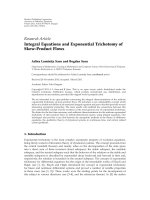
The frequency responses of the fourth subchannel filters
that are used for the filter bank with 2M
= 64 complex chan-
nels are plotted in Figure 8. The figure shows a frequency
modulated ELT prototype with overlapping factor K = 4and
another more frequency selective one with K = 6. In both
cases, the roll-off in the filter bank design is 100%, mean-
ing that each subchannel transition band is overlapping with
the closest transition band and passband of the adjacent sub-
channel, but not with the more distant ones.
Knowing the elements of this model, the number of af-
fected and eliminated subbands can be estimated for each
jammer power and a prediction for the expected perfor-
mance based on (12) can be plotted. Depending on the stop-
band attenuation of the prototype filter in the suppressor,
the number of affected subchannels varies with the power of
Filter-Bank-Based Interference Suppression 1169
K = 4
K = 6
00.10.20.30.40.50.60.70.80.91
Normalized frequency (×π rad/sample)
−100
−90
−80
−70
−60
−50
−40
−30
−20
−10
0
Magnitude (dB)
Figure 8: Frequency response for the analysis and synthesis banks
of one of the subchannel filters with K = 4andK = 6 where 2M =
64 subbands.
the jammer. Thus, if the filter characteristics are known, the
number of affected subbands can be predicted and the effec-
tive S/N from (12) can be calculated to obtain the estimated
BER for the two filter bank designs. An application of this
idea is presented in Figure 13.
5. PERFORMANCE EVALUATION
Simulations with the previously described model were
run with the following parameters: the spreading fac-
tor/processing gain of the spread spectrum system was g
p
=
127 and the spread signal was oversampled by 2. The fil-
ter bank was an ELT-based complex bank with 2M complex
channels (M on the positive and M on the negative sides
of the frequency band), decimation, and interpolation by M
and perfect reconstruction. The threshold factor used in the
jammer detection block was 2. For each point in the simu-
lation results, at least 10000 data bits were used to check the
BER. In the case of a randomly hopping jammer, the inter-
ferer hopped every 16 information bits and the simulations
were done with E
b
/N
0
= 7 dB. The results below extend the
ones presented in [23].
Figure 9 compares the results applying the recursive algo-
rithm with those that do not apply it with a 10% jammer and
a single tone jammer at a fixed position. The improvement in
the performance using the recursive algorithm is evident.
The previously mentioned effect of the transients is stud-
ied in Figure 10. The curves present the performance of a fil-
ter bank with 2M = 32 subbands and with different proto-
type filters K = 4andK = 6. It can be seen that without miti-
gating the transients, the results for both prototypes are very
similar and we are not completely taking advantage of the
higher stopband attenuation of the filter with higher over-
lapping factor K. However, when the guard interval method
No excision, tone jammer
No excision, 10% jammer
One-time detection, 10% jammer
One-time detection, tone jammer
Recursive algorithm, 10% jammer
Recursive algorithm, tone jammer
−60 −50 −40 −30 −20 −10 0
S/J ratio (dB)
10
−4
10
−3
10
−2
10
−1
10
0
BER
Figure 9: Performance without excision, with one-time excision,
and using the proposed recursive excision algorithm. E
b
/N
0
= 7dB,
2M = 32 subbands with K = 4, spreading factor = 127, 10% and
single tone jammers at fixed position. Guard-interval-based tran-
sient mitigation is applied.
No suppression
Suppression, K = 4
Suppression, K = 6
Suppression, K = 4 and guard interval
Suppression, K = 6 and guard interval
Suppression, K = 4 and guard bit
Noisefloor
−60 −50 −40 −30 −20 −10 0
S/J ratio (dB)
10
−4
10
−3
10
−2
10
−1
10
0
BER
Figure 10: Fighting the transients with guard interval and guard
bit. Filter prototypes with overlapping factors K = 4andK = 6,
where E
b
/N
0
= 7dB,2M = 32 subbands, spreading factor = 127,
10% jammer at randomly hopping positions.
1170 EURASIP Journal on Applied Signal Processing
No suppression
16 channels
32 channels
64 channels
128 channels
Noise floor
−60 −50 −40 −30 −20 −10 0
S/J ratio (dB)
10
−4
10
−3
10
−2
10
−1
10
0
BER
(a)
No suppression
16 channels
32 channels
64 channels
128 channels
Noise floor
−60 −50 −40 −30 −20 −10 0
S/J ratio (dB)
10
−4
10
−3
10
−2
10
−1
10
0
BER
(b)
No suppression
16 channels
32 channels
64 channels
128 channels
Noise floor
−60 −50 −40 −30 −20 −10 0
S/J ratio (dB)
10
−4
10
−3
10
−2
10
−1
10
0
BER
(c)
No suppression
16 channels
32 channels
64 channels
128 channels
Noise floor
−60 −50 −40 −30 −20 −10 0
S/J ratio (dB)
10
−4
10
−3
10
−2
10
−1
10
0
BER
(d)
Figure 11: Performance with oversampled (a, c) and chip rate (b, d) processing using different filter bank sizes with 2M = 16 to 128, where
K = 6, E
b
/N
0
= 7 dB, spreading factor = 127. (a, b) represent the single tone and (c, d) represent the 10% jammers at fixed positions.
Guard-interval-based transient mitigation is applied.
is applied, apart from an improvement in the performance in
both designs, we can see that the difference between the per-
formances grows. The figure also includes the guard bit ap-
proach as a lower BER bound for the guard interval method.
With a guard interval of 20 chips, the performance of the
guard interval idea is close to the performance of the guard
bit approach. In the figure we also include the noise floor,
representing the performance of the system when no jammer
is present.
Several parameters have been modified during the sim-
ulations to investigate their effect on the performance of the
system. For instance, the number of subchannels varied and
the downsampling by two was performed before the filter
bank (see the model in Figure 6), resulting in chip rate pro-
cessing at the filter bank. Figures 11 and 12 combine the re-
sults of these variations. We can see that using 2M = 32
gives a good performance with a reasonably low number of
subbands. For the case 2M = 16, the performance worsens,
Filter-Bank-Based Interference Suppression 1171
No suppression
16 channels
32 channels
64 channels
128 channels
Noise floor
−60 −50 −40 −30 −20 −10 0
S/J ratio (dB)
10
−4
10
−3
10
−2
10
−1
10
0
BER
(a)
No suppression
16 channels
32 channels
64 channels
128 channels
Noise floor
−60 −50 −40 −30 −20 −10 0
S/J ratio (dB)
10
−4
10
−3
10
−2
10
−1
10
0
BER
(b)
No suppression
16 channels
32 channels
64 channels
128 channels
Noise floor
−60 −50 −40 −30 −20 −10 0
S/J ratio (dB)
10
−4
10
−3
10
−2
10
−1
10
0
BER
(c)
No suppression
16 channels
32 channels
64 channels
128 channels
Noise floor
−60 −50 −40 −30 −20 −10 0
S/J ratio (dB)
10
−4
10
−3
10
−2
10
−1
10
0
BER
(d)
Figure 12: Performance with oversampled (a, c) and chip rate (b, d) processing using different filter bank sizes with 2M = 16 to 128, where
K = 6, E
b
/N
0
= 7 dB, spreading factor = 127. (a, b) represent the single tone and (c, d) represent the 10% jammers at randomly hopping
positions. Guard-interval-based transient mitigation is applied.
and the difference with higher number of subchannels is es-
pecially high in the case of low-to-medium power jammers.
Considering the case of chip rate processing, the width of the
spectrum relative to the sampling frequency at the filter bank
input is doubled, and this could allow having a filter bank
with fewer subbands. The processing load can thus also be
reduced in two ways, first by handling half the number of
samples, second by using a smaller filter bank. In this case we
see that also the filter bank with 2M = 16 subbands achieves
acceptable performance. Overall, using chip rate processing
results only in a minor degradation in performance if the fil-
ter banks size is chosen appropriately.
The size of the filter bank affects the length of the pro-
totype filter in its design: the larger M is used, the more co-
efficientsareneededforeachsubchannelfilter.Longersub-
channel filters cause also longer lasting transients, so a good
trade-off between the length of the guard interval and the
number of subbands in the bank has to be found.
1172 EURASIP Journal on Applied Signal Processing
Simulated BER without jammer elimination
Estimated BER without jammer elimination
Simulated BER after jammer removal
Noise floor
Estimated BER range after jammer removal
−60 −50 −40 −30 −20 −10 0
S/J ratio (dB)
10
−4
10
−3
10
−2
10
−1
10
0
BER
Figure 13: Expected BER range and obtained BER values over S/J
ratio in the optimised system with 2M = 32, K = 6, oversampled
processing, guard bit, E
b
/N
0
= 7 dB, spreading factor = 127, differ -
ent interference parameters.
We can compare the obtained results with the expected
performance of the derivations of Section 3 , taking into ac-
count the filter bank design proposed in Section 4. Figure 13
shows the estimated and simulated BER performances in the
cases in which the jammer is not removed and also when it is
removed. For the estimation of the BER range after the jam-
mer removal, the range in the numbers of removed subbands
at each S/J ratio was considered. Knowing the type of inter-
ference and its power and the noise level, it is possible to pre-
dict how much the interference will stick out of the uniform
DS-SS signal spectrum. Based on the stopband attenuation of
the filters in the filter bank, we can then estimate how many
subbands will be affected by the jammer, that is, get enough
jammer energy to modify the uniformity of the desired sig-
nal. With the number of affected and therefore eliminated
subbands and (12), we can calculate the expected degrada-
tion of the E
b
/N
0
ratio and consequently the expected BER.
Testing this idea on empirical measurements and counting
the maximum and minimum number of affected subbands
with different interference parameters, at each S/J ratio, we
were able to obtain the shaded area of Figure 13. The figure
shows that the expected results match quite well with the ob-
tained ones.
In another experiment, the processing was shortened into
blocks of 2 to 8 information bits, instead of 16 as in the pre-
vious results. Shorter processing blocks p ermit the tracking
and elimination of more quickly hopping jammers. The aim
was to see how short the blocks could be made before the per-
formance of the system decreased too much. Figures 14 and
15 reflect the results of this research. For a system of K = 6,
2M = 128 subbands at chip rate processing and using guard
bits, the conclusion is that the degradation in performance is
negligible for block lengths down to 6 bits, but beyond that
point it starts to be significant.
The results shown in this section are clearly better than
the ones presented in the reference method [8] using a 1024-
point FFT, as far as a direct comparison can be made. Ap-
parently, the 10% BPSK jammer in [8] did not have any kind
of pulse shaping, hence resulting in a more wideband signal
with sinc spectrum. We present in Figure 16 a comparison
between a filter bank with 32 subchannels and a 1024-point
FFT (no windowing) under a 10% fixed positioned jammer.
6. CONCLUSIONS
In this paper, a filter-bank-based interference detection and
excision method for a DS-SS system has been studied and
evaluated. The interfered subbands were removed from the
signal to eliminate the jammers. T he system worked with in-
terference at a fixed position and with interference that ran-
domly changed its position, with continuous wave interfer-
ence and with BPSK type of interference taking up to 10% of
the desired signal bandwidth.
The main strengths of the system presented in this paper
are the perfect reconstruction property of the filter bank used
and its affordable complexity requirements. It was shown
through simulations that the performance is close to the the-
oretical limit when all aspects of the system are carefully opti-
mised. The proposed system works quite well with far greater
S/J ratios than any of the transform domain techniques re-
ported in the literature. We can take the results of [12, Figure
3.14] as a reference. T hey show the performance of differ-
ent frequency domain excision methods in the case of 10%
jammer bandwidth and indicate best perfor mance for the
ELT-based approach. In those results, the performance de-
grades drastical ly (BER > 0.1) for S/J ratios lower than about
−45 dB. For comparison, we repeated our simulations with
similar parameters (5 dB E
b
/N
0
, almost the same spreading
code length, 63 instead of 64, but different spreading code).
These results, with properly optimised filter bank and recur-
sive jammer detection algorithm, indicate smoother degra-
dation with low S/J ratios providing tolerable performance
(BER < 0.1) for S/J above −75 dB with K = 6(−55 dB with
K = 4).
Implementing the perfect reconstruction filter bank with
ELTs, an efficient system is obtained, allowing the system to
work at high data rates. In [24], it was shown that the whole
excision system with overlapping factor K = 5 can be imple-
mented with a single TMS320C6414 DSP with sampling rate
in the order of 6–9 MHz, depending on the size of the filter
bank.
One significant aspect when comparing with most of the
other frequency domain approaches is that the needed num-
ber of subchannels is very low. Even with 16 subchannels, the
performance is close to the theoretical one.
All in one, the narrowband interference suppression
method presented is a good compromise between com-
plexity, efficiency, and performance at relatively high jam-
mer powers. In [9], a similar conclusion is drawn when
Filter-Bank-Based Interference Suppression 1173
−60 −50 −40 −30 −20 −10 0
S/J ratio (dB)
10
−4
10
−2
10
0
BER
8bits
−60 −50 −40 −30 −20 −10 0
S/J ratio (dB)
10
−4
10
−2
10
0
BER
4bits
(a)
−60 −50 −40 −30 −20 −10 0
S/J ratio (dB)
10
−4
10
−2
10
0
BER
6bits
−60 −50 −40 −30 −20 −10 0
S/J ratio (dB)
10
−4
10
−2
10
0
BER
2bits
(b)
−60 −50 −40 −30 −20 −10 0
S/J ratio (dB)
10
−4
10
−2
10
0
BER
8bits
−60 −50 −40 −30 −20 −10 0
S/J ratio (dB)
10
−4
10
−2
10
0
BER
4bits
(c)
−60 −50 −40 −30 −20 −10 0
S/J ratio (dB)
10
−4
10
−2
10
0
BER
6bits
−60 −50 −40 −30 −20 −10 0
S/J ratio (dB)
10
−4
10
−2
10
0
BER
2bits
(d)
Figure 14: Different processing block lengths of 2 to 8 bits. Filter bank with 2M = 128, K = 6, chip rate processing, guard bit, E
b
/N
0
= 7dB,
and spreading factor = 127. (a), (b) represent the single tone and (c), (d) represent the 10% jammers at fixed positions. Dashed lines
represent simulated BER without jammer removal, solid lines represent simulated BER after jammer removal, and dotted lines represent
noise floor.
comparing ELT, FFT, and DCT methods. Better performance
at increasing jammer powers can be obtained by using proto-
type filters that are more frequency selective and have higher
stopband attenuation. However, the limiting factors can be
at earlier stages in the receiver. For example, the resolution
of the A/D converter has to be good enough to represent a
desired signal that is, for instance, 70 dB weaker than the in-
terfering signal that is also being sampled simultaneously.
We have studied the performance of the proposed
method only in the single-user case. In multiuser CDMA en-
vironment, the effect of the notch filtering due to filter bank
excision on the multiple access interference (MAI) is a se-
rious concern. Considering the case of very strong narrow-
band interference, it is obvious that the best thing to do also
from the MAI point of view is to remove the interfered fre-
quency band completely since it could not include any useful
information for detection. However, in this context, the use
of higher number of subchannels than needed in the single-
user case could be favourable. In case of modest jammer lev-
els, subband excision is clearly a suboptimal solution and
1174 EURASIP Journal on Applied Signal Processing
−60 −50 −40 −30 −20 −10 0
S/J ratio (dB)
10
−4
10
−2
10
0
BER
8bits
−60 −50 −40 −30 −20 −10 0
S/J ratio (dB)
10
−4
10
−2
10
0
BER
4bits
(a)
−60 −50 −40 −30 −20 −10 0
S/J ratio (dB)
10
−4
10
−2
10
0
BER
6bits
−60 −50 −40 −30 −20 −10 0
S/J ratio (dB)
10
−4
10
−2
10
0
BER
2bits
(b)
−60 −50 −40 −30 −20 −10 0
S/J ratio (dB)
10
−4
10
−2
10
0
BER
8bits
−60 −50 −40 −30 −20 −10 0
S/J ratio (dB)
10
−4
10
−2
10
0
BER
4bits
(c)
−60 −50 −40 −30 −20 −10 0
S/J ratio (dB)
10
−4
10
−2
10
0
BER
6bits
−60 −50 −40 −30 −20 −10 0
S/J ratio (dB)
10
−4
10
−2
10
0
BER
2bits
(d)
Figure 15: Different processing block lengths of 2 to 8 bits. Filter bank with 2M = 128, K = 6, chip rate processing, guard bit, E
b
/N
0
= 7dB,
and spreading factor = 127. (a), (b) represent the single tone and (c), (d) represent the 10% jammers at randomly hopping positions.
Dashed lines represent simulated BER without jammer removal, solid lines represent simulated BER after jammer removal, and dotted lines
represent noise floor.
its performance comparisons against other interference sup-
pression methods are a topic for future studies. Also a more
analytical study of the recursive jammer detection methods
is included in the future plans.
ACKNOWLEDGMENT
This work was carried out in the project “Digital and Ana-
log Techniques in Flexible Receivers” funded by the National
Technology Agency of Finland (Tekes).
Filter-Bank-Based Interference Suppression 1175
No suppression
1024-point FFT
32 subchannel FB
Noise floor
−60 −50 −40 −30 −20 −10 0
S/J ratio (dB)
10
−4
10
−3
10
−2
10
−1
10
0
BER
Figure 16: Comparison between a filter bank with 2M = 32,
K = 6 and oversampled processing and a 1024-point FFT, where
E
b
/N
0
= 7 dB, spreading factor = 127 and the 10% jammer is at a
fixed position. Guard-interval-based transient mitigation is applied.
REFERENCES
[1] J. G. Proakis, Digital Communications, Electrical Engineering
Series. McGraw-Hill International Editions, New York, NY,
USA, 4th edition, 2001.
[2] L. B. Milstein, “Interference rejection techniques in spread
spectrum communications,” Proceedings of the IEEE, vol. 76,
no. 6, pp. 657–671, 1988.
[3] F. Hsu and A. Giordano, “Digital whitening techniques for
improving spread spectrum communications performance in
the presence of narrowband jamming and interference,” IEEE
Trans. Communications, vol. 26, no. 2, pp. 209–216, 1978.
[4] J. W. Ketchum and J. G. Proakis, “Adaptive algorithms for
estimating and suppressing narrow-band interference in PN
spread-spectrum systems,” IEEE Trans. Communications, vol.
30, no. 5, pp. 913–924, 1982.
[5] R. A. Iltis and L. B. Milstein, “Performance analysis of narrow-
band interference rejection techniques in DS spread-spectr um
systems,” IEEE Trans. Communications, vol. 32, no. 11, pp.
1169–1177, 1984.
[6] P. Henttu, H. Saarnisaari, and S. Aroinaa, “Interference sup-
pression in DS/FH system using modified two sided adaptive
filter,” in Proc. IEEE Military Communications Conference,pp.
1429–1433, McLean, Va, USA, October 2001.
[7] M. J. Medley, G. J. Saulnier, and P. K. Das, “Narrow-band
interference excision in spread spectrum systems using lapped
transforms,” IEEE Trans. Communications, vol. 45, no. 11, pp.
1444–1455, 1997.
[8] A. Pouttu, J. K. Juntti, and T. J. Kumpum
¨
aki, “Adaptive trans-
form domain interference suppression in a hybrid DS/FH-
system,” in Proc. IEEE 5th International Symposium on Spread
Spectrum Techniques and Applications, pp. 351–355, Sun City,
South Africa, September 1998.
[9] P. Henttu, A. Pouttu, and M. Raustia, “Performance of PIE
interference suppressor using FFT, DCT and ELT transforma-
tions in FH/DS communications,” in Proc. Information Sys-
tems for Enhanced Public Safety and Security. IEEE/AFCEA,pp.
126–130, Munich, Germany, May 2000.
[10] R. A. Monzingo and T. W. Miller, Introduction to Adaptive
Arrays, John Wiley & Sons, New York, NY, USA, 1980.
[11] M. V. Tazebay and A. N. Akansu, “Adaptive subband tr ans-
forms in t ime-frequency excisers for DSSS communications
systems,” IEEE Trans. Signal Processing, vol. 43, no. 11, pp.
2776–2782, 1995.
[12] A. N. Akansu and M. J. Medley, Wavelet, Subband, and Block
Transforms in Communications and Multimedia,KluwerAca-
demic, Boston, Mass, USA, 1999.
[13] P. P. Vaidyanathan, Multirate Systems and Filter Banks,
Prentice-Hall Signal Processing Series. Prentice-Hall, Engle-
wood Cliffs, NJ, USA, 1993.
[14] T. J. Kumpum
¨
aki, M. A. Isohookana, and J. K. Juntti,
“Narrow-band interference rejection using transform domain
signal processing in a hybrid DS/FH spread spectrum system,”
in Proc. IEEE Military Communications Conference, pp. 89–93,
Monterey, Calif, USA, November 1997.
[15] T. Karp and N. J. Fliege, “Modified DFT filter banks with
perfect reconstruction,” IEEE Trans. on Circuits and Systems
II: Analog and Digital Signal Processing, vol. 46, no. 11, pp.
1404–1414, 1999.
[16] A. Viholainen, T. H. Stitz, J. Alhava, T. Ihalainen, and M. Ren-
fors, “Complex modulated critically sampled filter banks
based on cosine and sine modulation,” in Proc. IEEE
Int. Symp. Circuits and Systems, pp. 833–836, Scottsdale, Ariz,
USA, May 2002.
[17] H. S. Malvar, Signal Processing with Lapped Transforms,Artech
House, Boston, Mass, USA, 1992.
[18] J. Alhava, A. Viholainen, and M. Renfors, “Efficient imple-
mentation of complex exponentially-modulated filter banks,”
in Proc. IEEE Int. Symp. Circuits and Systems, pp. 157–160,
Bangkok, Thailand, May 2003.
[19] H. S. Malvar, “A modulated complex lapped transform
and its applications to audio processing,” in Proc. IEEE
Int. Conf. Acoustics, Speech, Signal Processing, pp. 1421–1424,
Phoenix, Ariz, USA, March 1999.
[20] R. W. Young and N. G. Kingsbury, “Frequency-domain mo-
tion estimation using a complex lapped transform,” IEEE
Trans. Image Processing, vol. 2, no. 1, pp. 2–17, 1993.
[21] A. Viholainen, J. Alhava, and M. Renfors, “Implementation of
parallel cosine and sine modulated filter banks for equalized
transmultiplexer systems,” in Proc. IEEE Int. Conf. Acoustics,
Speech, Signal Processing, pp. 3625–3628, Salt Lake City, Utah,
USA, May 2001.
[22] P. Henttu, “Signaalikomponenttien erottaminen radioj
¨
arjes-
telm
¨
an vastaanottimessa,” in Suomalainen Pattentihakemus
nro. 20010952 , Nokia Networks Oy, Finland, 2001.
[23] T. H. Stitz and M. Renfors, “Filter bank based narrowband in-
terference detection and suppression in spread spectrum sys-
tems,” in Proc. IEEE Int. Symp. Circuits and Systems, pp. 516–
519, Phoenix-Scottsdale, Ariz, USA, May 2002.
[24] Y. Yang, T. H. Stitz, and M. Renfors, “Implementation of a
filter bank based narrowband interference suppression algo-
rithm on a DSP processor,” in Proc. International Conference
on Telecommunications, Beijing, China, June 2002.
Tobias Hidalgo Stitz was born in 1974 in
Eschwege, Germany. He obtained the M.S.
degree in telecommunications engineering
from the Polytechnic University of Madrid
(UPM) in 2001, after writing his Master’s
thesis at the Institute of Communications
Engineering of the Tampere University of
Technology (TUT). From 1999 to 2001, he
was a Research Assistant at TUT and is now
1176 EURASIP Journal on Applied Signal Processing
working towards his doctoral degree there. His research interests
include wireless communications based on multicarrier systems,
especially focusing on filter-bank-based systems and other filter
bank applications for signal processing.
Markku Renfors was born in Suoniemi,
Finland, on January 21, 1953. He received
the Diploma Engineer, Licentiate of Tech-
nology, and Doctor of Technology degrees
from Tampere University of Technology
(TUT) in 1978, 1981, and 1982, respectively.
He held various research and teaching po-
sitions at TUT from 1976 to 1988. In the
years 1988–1991, he was working as a De-
sign Manager in the area of video signal pro-
cessing, especially for HDTV, at Nokia Research Centre and Nokia
Consumer Electronics. Since 1992, he has been a Professor and
Head of the Institute of Communications Engineering at TUT. His
main research areas are multicarrier systems and signal processing
algorithms for flexible radio receivers and transmitters.