Báo cáo hóa học: " Multiplierless Implementation of Rotators and FFTs" doc
Bạn đang xem bản rút gọn của tài liệu. Xem và tải ngay bản đầy đủ của tài liệu tại đây (589.25 KB, 8 trang )
EURASIP Journal on Applied Signal Processing 2005:17, 2903–2910
c
2005 Malcolm D. Macleod
Multiplierless Implementation of Rotators and FFTs
Malcolm D. Macleod
QinetiQ Ltd., St. Andrews Road, Malvern, Worcestershire WR14 3PS, UK
Email:
Received 9 December 2004; Revised 26 June 2005; Recommended for Publication by Markus Rupp
Complex rotators are used in many important signal processing applications, including Cooley-Tukey and split-radix FFT al-
gorithms. This paper presents methods for designing multiplierless implementations of fixed-point rotators and FFTs, in which
multiplications are replaced by additions, subtractions, and shifts. These methods minimise the adder-cost (the number of addi-
tions and subtractions), while achieving a specified level of accuracy. FFT designs based on multiplierless rotators are compared
with designs based on the multiplierless implementation of DFT matrix multiplication. These techniques make possible VLSI
implementations of rotators and FFTs which could achieve very high speed and/or power efficiency. The methods can be used to
provide any chosen accuracy; examples are presented for 12 to 26 bit accuracy. On average, rotators are shown to be implementable
using 10, 12, or 15 adders to achieve accuracies of 12, 16, or 20 bits, respectively.
Keywords and phrases: FFT implementation, rotator implementation, multiplierless design, VLSI.
1. INTRODUCTION
Complex rotators, which multiply input values by e
jθ
for
some θ, are used in many important applications, includ-
ing fast fourier transform (FFT) algorithms, where they are
also known as “twiddle factors” [1]. Many current systems
require embedded FFTs, including orthogonal frequency-
division multiplexing modems for digital broadcasting, wire-
less networking, and telecommunications, and many more
potential applications are anticipated.
Because the real and imaginary parts of e
jθ
are in gen-
eral irrational, the computation of such rotations, and of the
FFT, is inherently inexact [1], so the requirement is always
to achieve sufficient accuracy for an intended application. To
reduce power consumption and increase speed, fixed-point
arithmetic is often used.
Until recently, research into implementation of these
functions has concentrated on architectures such as pro-
grammable DSP ICs, containing multiplier-accumulators.
With recent advances in VLSI technology, “multiplierless” al-
gorithms now provide the option of further lowering power
consumption and IC area, or greatly increasing throughput.
In multiplierless algorithms, general-purpose multi-
pliers are replaced by binary shifts, adders, subtrac ters,
negaters, and stores. As is common when considering VLSI
hardware implementations, binary shifts and data moves are
treated as costless, while stores and negaters are assumed to
This is an open access article distr ibuted under the Creative Commons
Attribution License, which permits unrestricted use, distribution, and
reproduction in any medium, provided the original work is properly cited.
be significantly less costly (in area or power consumption)
than adders. Therefore subtracters are assumed to have the
same cost as adders [2], and the measure of the implementa-
tion cost which is used is the “adder-cost”, which is the total
number of subtracters and adders.
Techniques have been developed for the minimum-
adder-cost implementation of individual multiplications [2,
3, 4], digital filters [5, 6, 7], and matrix multiplications
[7, 8, 9], including the DFT matrix [8].
Methods have also been described for designing multi-
plierless DCTs [10, 11], and for multiplierless implemention
of the Winograd and prime-factor Fourier t ransform algo-
rithms [12].
This paper describes methods for the desig n of min-
imum-adder-cost multiplierless rotators, and of Cooley-
Tukey FFTs and related transforms such as the split-radix
FFT. FFT designs based on multiplierless rotators are also
compared with designs based on the multiplierless imple-
mentation of DFT matrix multiplication.
Rotators are complex multiplications by w = c+ js,where
s = sin θ and c = cos θ.Ifθ = kπ/2, for k integer, then
implementation of the rotation is trivial (i.e., does not re-
quire any adders). Otherwise both c and s have magnitude
less than one, so if they are represented as fixed-point two’s-
complement values, they require only one (sign) bit before
the binary point, and b bits after it, where b + 1 is the cho-
sen wordlength. Multiplication by such a fixed-point value c
is therefore equivalent to multiplication by the integer 2
b
c
followed by division by 2
b
; hence without loss of general-
ity all multiplication coefficients may be assumed to be in-
tegers.
2904 EURASIP Journal on Applied Signal Processing
This paper will show that many alternate implementa-
tion structures must be searched in order to minimise rota-
tor adder-cost. This expanded search procedure and the re-
sulting low-cost multiplierless designs for rotator and FFT
implementation are the novel contributions of the paper.
2. EXISTING MULTIPLIERLESS FFTs
FFT algorithms have a multistage structure. An N-point
radix-M FFT consists of log
M
N stages, each containing
(N/M) M-point DFTs, alternating with stages consisting of
complex rotators. Radix-2 and radix-4 FFTs are widely used,
because 2- and 4-point DFTs contain only trivial multiplica-
tions by ±1or±j, but other choices of radix, mixed-radix,
or split-radix FFTs [13] are possible.
Despain [1] commented that in many applications a fixed
phase offset, or an arbitrary fi xed scaling, of all the FFT out-
puts is al lowable, and can if necessary be compensated for
later, at low cost. If any such scaling is used, the same scaling
must be applied to all data passing through any given stage
of the FFT.
Despain described a modified radix-4 16-point Cooley-
Tukey FFT [1] in which low adder-cost was achieved by al-
lowing a common phase offset and scale factor to be applied
to all the FFT outputs.
Perera and Rayner [14] described radix-4 FFTs based on
blocks, e ach equivalent to a 4-point DFT and 4 rotations, but
implemented as a 4 × 4 matr ix multiplication, in which each
multiplier coefficient was constrained to be a sum of pow-
ers of two (SOPOT) with at most 1 adder (i.e., either ±2
k
or
±2
k
± 2
m
).
A recent more general method [15] implements rota-
tors in a conventional FFT structure, using a specific rotator
structure together with optimised SOPOT coefficients, hav-
ing a user-selectable maximum number of adders.
3. ALGORITHMS FOR MULTIPLIERLESS DESIGN
For individual constant multipliers, the use of canonic signed
digit (CSD) representation requires on average 33% fewer
adders than those required by normal binary [2]. Structures
with fewer adders than CSD can be found which use factored
and other forms; for example, 45x = (1+4)×(1+8)x only re-
quires 2 adders, whereas multiplication using the CSD form
requires 3. Such struc tures may be found using the exhaus-
tive minimised adder graph (MAG) algorithm [3], applied
to integer coefficients up to 2
12
in [3],andextendedto2
19
in
[4], or suboptimal algorithms such as those in [2].
In applications where two or more products of the same
input value are required simultaneously, such as transposed-
form digital filters, a multiplier block [6, 7, 8, 16]maybeused,
and the number of adders may then be reduced by sharing
terms. For example, to produce 9x,45x,and13x simultane-
ously, we may generate 9x = (8 + 1)x,45x = (4 + 1) × 9x,
and 13x = 9x +4x, at a total cost of 3 adders. A dependence-
graph algorithm for designing minimum-adder-cost multi-
plier blocks was introduced by Bull and Horrocks [17]. In
such algorithms graph edges represent binary shifts and/or
negation, and graph vertexes (nodes) represent adders. An
improved algorithm, named “Bull and Horrocks modified”
(BHM), was presented in [6], together with another algo-
rithm named “n-dimensional reduced adder graph” (RAG-
n). Reduced-adder-cost multiplier blocks may also be de-
signed using common subexpression elimination (CSE)
methods, for example [7, 16].
CSE methods may also be used to design reduced-cost
multiplierless matrix multiplications [7, 8], in which there
may be common subexpressions not only across outputs (as
in multiplier blocks) but also across inputs.
4. ROTATOR IMPLEMENTATION OPTIONS
A rotation is a multiplication by w = c + js,wheres = sin θ
and c = cos θ, with the result u + jv = (c + js)(x + jy) =
(cx − sy)+j(sx + cy). It can be computed
(i) directly, using four separate multipliers (two by c and
two by s) and two additions;
(ii) by using a multiplier block to compute cx and sx si-
multaneously, and another identical one to compute cy and
sy, followed by two additions;
(iii) as c(x−y)+(c−s)y+ j(s(x+y)+(c−s)y); this requires
3 multiplications (by c, s,and(c − s)) and 4 additions;
(iv) as y(c − s)+(x − y)c + j(x(c + s) − (x − y)c); this
requires 3 multiplications (by c,(c + s), and (c − s)) and 3
additions;
(v) as x(c−s)+(x−y)s+ j(y(c+s)+(x−y)s); this requires
3 multiplications (by s,(c + s), and (c − s)) and 3 additions;
(vi) as in [15] by factorising the matrix representation of
the complex rotation,
u
v
=
c −s
sc
x
y
,(1)
as
c −s
sc
=
1 t
0 −1
10
−s 1
1 −t
0 −1
,(2)
where s = sinθ and t = tan(θ/2); this requires 3 multiplica-
tions (one by s and two by t) and 3 additions;
(vii) by noting that a rotation by angle θ can be imple-
mented as successive rotations by angles φ and (θ
− φ), as in
the CORDIC algorithm [18]; or
(viii) by treating the rotation as a matrix multiplication
as shown in (1), to which matrix CSE methods [7, 8]canbe
directly applied.
Despain’s designs [1] use several (but not all) of the above
options.
For the rotator-type (vii) we limited the number of cas-
caded rotations to two, partly to reduce search time and also
because the adder-cost overhead of using more than two ro-
tators makes a low-cost solution less likely to occur.
For rotator types (iii), (iv), and (v), two quantisation op-
tions are possible. The first is to round c, s, c + s,andc −s in-
dependently. However, the rounded versions of c + s and c −s
may not equal the sum/difference of the rounded versions of
c and s. In that case, the gain and phase shift produced by the
quantised structure may vary slightly with the argument of
the input value. This may also happen for rotator type (vi).
Multiplierless Implementation of Rotators and FFTs 2905
The second option, w hich we label (iii a), (iv a), or (v a),
is to quantise c ± s to the sum or difference of the rounded
values of c and s. For these variants, the gain and phase shift
are independent of input argument.
For the special case of rotations by odd multiples of π/4,
a simpler structure is possible because c =±s. First, cx and
cy are computed, and then two further additions or subtrac-
tions produce the result.
5. ROTATOR OPTIMISATION
To design the multiplierless form of one of the rotator types
described in Section 4,givenadesiredrotationangle,we
multiply its coefficients by an integer scale factor k, round-
ing the results to integers, and then evaluate its accuracy and
adder-cost. To find the minimum-adder-cost solution which
achieves the required accuracy, a search is carried out over a
range of values of k, and over all the rotator types described
in Section 4. If the overall gain of the rotator is required to
be unity, k is restricted to be a positive power of two, so that
the gain can be made unity by a simple shift. If the nonunity
overall gain is acceptable, then k is allowed to be any integer.
Before starting the search, the minimum-adder-cost so-
lutions for individual multiplications by each positive integer
coefficient value up to a chosen maximum are precomputed,
using the algorithms in [2, 3], and stored.
For rotator types (i), (iii), (iv), (v), (vi) and (iii a), (iv
a), (v a), these precomputed individual multiplier designs are
used, while for option (ii), which uses multiplier blocks, two
multiplier-block design methods, BHM [6]andRAG-n [6],
are applied and the results are compared. For the matrix CSE
approach (viii), the algorithm described in [8]wasused.
The two-stage rotator option (vii) has to b e searched dif-
ferently, for efficiency. First, all possible rotators having inte-
ger real and imaginary coefficients c and s which are either
positive powers of two (SOPOT-0) or the sum of two such
values (SOPOT-1) were generated, up to a specified maxi-
mum (in this paper, the maximum was set to 2
16
). The re-
striction to SOPOT-1 coefficients and the limited maximum
magnitude are arbitrary, but they limit search time and stor-
age requirements.
Next, all possible cascade combinations of two of these
rotators (with either the same or opposite signs of the rota-
tion angle) are generated, and the resulting equivalent com-
plex multiplication coefficient of the combined rotator, c
e
+
js
e
, is stored, along with its adder-cost.
Then, during the search phase, for a given scale factor k,
each of the stored coefficients c
e
+ js
e
in turn is multiplied by
whichever integer power of two, 2
K
, makes the resulting coef-
ficient magnitude (2
K
c
2
e
+ s
2
e
) closest to k, and the resulting
error and cost are evaluated.
5.1. Accuracy measurement
The root-mean-square (RMS) error due to rounding ran-
dom coefficients to binary fixed-point values with b bits af-
ter the binary point is 2
−b
/
√
12. Consider a set of two or
more actual coefficients, and let their actual RMS error be σ
C
;
for example, for a rotator, the actual (rounded) coefficients
might be given by c
Q
= round(kc)ands
Q
= round(ks), and
then σ
C
=
(c
Q
/k − c)
2
+(s
Q
/k − s)
2
. We define the accuracy
of such a set of coefficients as
ˆ
b =−log
2
√
12σ
C
bits. (3)
Using this definition, a set of coefficients quantised with
b bits after the binary point will give an accuracy
ˆ
b from (3)
which is close to b bits. This allows a direct comparison be-
tween the accuracy actually achieved in a given case and that
which one would expect to achieve by rounding coefficients
to a given wordlength.
Despain [1] defined a term “precision”, also measured in
bits, which measures only the angular error, ∆θ, of a rota-
tor and is given by log
2
(2π/∆θ); these “precision” values are
2.5 − 3.3 bits greater than the corresponding “accuracy” val-
ues given by (3).
For rotator types (i), (ii), (iii a), (iv a), (v a), and (viii),
the actual multiplication coefficient of the rotator is that ob-
tained by quantising the values of c and s. For rotator type
(vii), the effective coefficient is in general different. For ro-
tator types (iii), (iv), (v), and (vi), the gain and phase shift
produced by the quantised structure may vary slightly with
the argument of the input value, therefore to compute the
effective coefficient and accuracy of the rotator we com-
pute the gain and mean-squared error over all input argu-
ments. It is straightforward to show that this error is a peri-
odic function of the input argument, with period π/2. Hence
the effective coefficient and the squared error are computed
over a uniformly-spaced set of input arguments in the range
0 ···π/2, and the resulting mean-squared error is then used
in (3).
5.2. Results
To demonstrate the results achievable by this a pproach, we
designed rotators for the set of rotation arguments p2π/1024,
p = 1 ···128, using 3 scale factors, k = 2
12
,2
15
,and2
18
; this
leads to accuracies of approximately 12, 15, and 18 bits. The
results, presented in Tabl e 1, are all averaged over the set of
128 angles.
Table 1 also shows, for reference, the cost of a type (i) ro-
tator using CSD coefficients, and the overall optimum cost,
obtained by selecting the lowest cost rotator for each rota-
tion angle. The average cost of each individual rotator type
is also shown, a long with the percentage of rotation angles
for which that t ype achieved the minimum cost. The av-
erages in Tabl e 1 are over only those angles for w hich the
chosen type has a solution of sufficient accuracy. Because of
the limits imposed when constructing two-stage rotator op-
tions (vii), such rotators could not achieve accuracies of 12
or 15 bits for all angles, which is why the average cost shown
in Table 1 is lower than the minimum; they never achieved
18-bit accuracy. RAG-n was also not used for 18-bit accu-
racy, because the tables it requires, which grow rapidly in
size with wordlength, had not been computed to sufficient
wordlength.
2906 EURASIP Journal on Applied Signal Processing
Table 1: Average adder-costs (AC
AV
)ofrotatorsofaccuracyb = 12, 15, and 18 bits, designed by different methods. % min is the percentage
of cases in which the corresponding method achieved the minimum cost (AC
MIN
).
Bits b 12 12 15 15 18 18
Type AC
AV
%min AC
AV
%min AC
AV
%min
(i) 13.48 7 15.92 5 18.25 3
(ii) BHM 12.47 18 14.93 9 17.24 6
(ii) RAG 11.98 34 15.02 20 — 0
(iii) 12.72 2 14.64 4 16.40 5
(iv) 12.20 20 14.13 14 16.17 22
(v) 12.22 16 14.06 17 16.07 24
(iii a) 12.70 2 14.58 4 16.43 3
(iv a) 12.17 24 14.09 17 16.18 23
(v a) 13.19 23 14.02 20 16.09 26
(vi) 11.22 49 12.98 56 14.73 66
(vii) 10.07 30 10.43 9 — 0
(viii) 11.57 38 13.92 31 16.09 23
(i) CSD 15.36 0 19.25 0 23.00 0
AC
MIN
10.29 — 12.21 — 14.03 —
It can be seen that the minimum cost is about two
thirds of the cost of a conventional CSD implementation. No
method is always optimum, which demonstrates the need to
search all types. Of the individual types, type (vi) has the
lowest average cost and the highest rate in achieving min-
imum cost, especially as the wordlength increases. Of the
other types, type (viii) and type (ii) using RAG-n perform
well for 12-bit wordlength. Types (iv), (v), (iv a), and (v a)
perform fairly well for all wordlengths.
6. MULTIPLIERLESS FFT DESIGN
One option for multiplierless implementation of the FFT is
to replace the rotators in a conventional FFT structure by
multiplierless rotators. Another option, for a radix-2 FFT, is
to treat the butterflies as complex 2 × 2 matrix multiplica-
tions (equivalent to 4 × 4 real matrix multiplications) and
apply CSE to them, or similarly, for a radix-P FFT to treat
the basic processing units (which consist of P − 1nontriv-
ialrotatorsandaP-point FFT) as matrix multiplications. A
third option is to implement the entire DFT as a matrix mul-
tiplication and apply CSE to it [ 8].
1
6.1. FFT accuracy and output SNR
Assume that all coefficients are quantised with b bits after the
binary point, and that the data wordlengths are sufficiently
large so that the output noise due to requantisation (at “mul-
tiplier” outputs) is negligible. Then at the output of a radix-2
N-point FFT, the ratio of the average output error variance
due to coefficient quantisation to the output signal variance
1
The author is grateful to an anonymous referee for these two sugges-
tions.
is given approximately by [19]
σ
2
EO
σ
2
O
≈ 2
−2b
log
2
N
6
. (4)
This formula (4) takes into account the fact that trivial
rotations (i.e., those which rotate by integer multiples of π/2)
are computed with no error.
To characterise the accuracy of an FFT, it is therefore nec-
essary to compute the effective wordlength b of the nontrivial
rotators. To do this, we first compute the RMS error of each
nontrivial rotator in the FFT, and set σ
C
equal to the RMS of
those errors, then use (3) to define an overall
ˆ
b-bit accuracy,
suitable for use in (4).
An alternative method of assessing accuracy of finite-
precision FFTs and DFTs [15] is to compute the Frobenius
norm of the error between the effective DFT matrix, F
E
,of
the finite-precision transform and the exact DFT matrix, F,
that is, the square root of the sum of absolute squares of the
elements of F
E
− F.
6.2. Optimisation approach
The user must first define the transfor m size N and the re-
quired accuracy.
For the approach in which the whole DFT is treated as
a matrix multiplication, the DFT matrix elements are mul-
tiplied by an integer scale fac tor k and rounded. The CSE
algorithm from [9] is then applied to the result. As before, if
an overall gain of unity is required, then k is made a power
of two (the required power of two can be deduced from the
required accuracy). But if arbitrary gain is allowed, then a
range of values of k is searched to find the one which gives
the required accuracy with lowest cost.
For the approaches in which the rotators (or butterflies
or radix-P units) in an FFT are replaced by multiplierless
Multiplierless Implementation of Rotators and FFTs 2907
Table 2: Adder-cost (AC) and accuracy of DFTs designed by CSE
methods from [8, 9]. (N = FFT length; b = bits after binary point;
acc. = accuracy (bits).)
N
b
Acc.
Adder-cost
CSD [8][9]
8811.9 400 80 64
816 18.5 528 84 68
16 16 16.1 3296 364 220
implementations, the user specifies the FFT radix and struc-
ture (e.g., mixed or split radix). The simplest optimisation
method, which we call uniform (U-) scaling, is to apply the
same scale factor k to all paths through every stage of the FFT
(apart from stages which contain only trivial rotations). For
each value of k in turn, the minimum-adder-cost rotators are
found as described in Section 5, or the butterflies (or radix-P
units) are represented as fixed-point matrices and CSE is ap-
plied to them. If k is not a power of 2, then each path with
gain 1.0or±j in the unscaled FFT must be multiplied by
1.0k or ±jk in the scaled FFT, and for this, the precomputed
minimum-adder-cost solutions for individual real multipli-
cations are used.
For rotator-based designs, it is only necessary to design
rotators with rotation angles in the set (0, 1, , N/8)×2π/N,
because all the other required rotations are simple costless
transformations of these [15].
For each value of k in turn, the minimum-adder-cost and
RMS accuracy of all the rotators are determined. Finally, the
value of k is determined which gives the minimum-cost so-
lution that achieves at least the specified minimum-RMS ac-
curacy.
The use of a common scale factor could give rise to a sit-
uation in which some rotators (or butterflies, etc.) are sig-
nificantly more accurate than others, and so could be imple-
mented w ith sufficient accuracy at lower cost. Therefore in a
second method (called compatible (C-) scaling) the rotators
are allowed to have different integer scale factors whose ratios
are powers of 2, so that subsequent binary shifts can be used
to restore a single scale factor. In this method, the minimum
costs and errors are first computed for each rotation angle
separately, for each scale factor, and stored. Each scale factor
k in turn is then selected, and the stored results for all com-
patible scale factors (i.e., those equal to k2
p
≤ k
max
for p ≥ 0)
are tested. The minimum-cost set in which all rotators have
errors less than the specified limit is selected.
Only the two strategies described above were used for
this paper. We also did not allow arbitrar y phase rotations,
as used in [1]. Alternative scaling strategies might produce
further improvements; for example, a different scale factor
could be allowed for each FFT stage.
6.3. Results
For the method in which butterfly units are treated as matrix
multiplications, and CSE is applied, the resulting adder-cost
Table 3: Adder-cost (AC) and accuracy of FFTs designed by the
methods in this paper and [15]. (N = FFT length; sc. = scaling type;
acc. = accuracy (bits); FN = Frobenius norm of error (dB).)
N
Radix
Sc.
Our methods Methods in [15]
AC Acc. FN AC FN
32
2U 616 11.5 −46 756 −45
2/4 U 576 12.2 −46 ——
128
2U4800 13.4 −41 6727 −41
2/4 C 3648 13.4 −41 ——
was found to be always equal to that achieved by designing
the corresponding rotator using CSE (i.e., rotator type (viii))
and adding four real adders to complete the butterfly. In the
case of radix-4 units, CSE applied to the whole radix-4 unit
required on average almost twice as many adders as the use
of three type-(viii) rotators together with the 16 real adders
required for a 4-point FFT. Therefore these options were not
considered fur ther.
The results obtained by applying CSE to the entire fixed-
point DFT matrix multiplication are shown in Table 2 .Re-
sults are presented for 8- and 16-point DFTs w ith either 8
or 16 bits after the binary point, using the CSE methods
in [8, 9]. (Note that the results in [8, Table VIII] are only
for part of the computation; Table 2 shows the total adder-
count using the method in [8].) It can be seen that the ma-
trix CSE method in [9] gives lower adder-cost. These adder-
costs equal those achieved for FFTs based on multiplierless
rotators (as can be seen from the corresponding entries in
Table 5), but for the 16-point DFT the computation time of
the CSE method was approximately 1000 times greater, and
this ratio was found to increase exponentially with transform
size and wordlength, making this method much less attrac-
tiveforlargertransforms.
For rotator-based FFTs, only power-of-2 (PO2) scale fac-
tors ever achieved minimum cost. This is because a signifi-
cant number of the paths through each stage of an FFT have
an unscaled gain of unity. For example, in radix-2 FFTs there
are more unit gain paths than rotators, and in radix-4 FFTs
over a quarter of all paths have unit gain. If a non-PO2 scale
factor is used, the adder-cost of multiplying every such path
by that scale factor always outweighs any savings in the cost
of the rotators.
The difference between U-scaling and C-scaling was
small, but because the two scalings produce difference op-
tions for cost and accuracy, either can be slightly advanta-
geousinanygivencase.
Table 3 presents results for designs to meet the specifica-
tions of the length-32 and -128 radix-2 designs presented in
[15]. It also shows the Frobenius norm of the error matrix,
to allow comparison with [15]. The length-32 radix-2 FFT
design using the methods of this paper requires 140 adders
fewer than that in [15]. This is a reduction of 33% in the
rotator adder-cost, but only an 18.5% reduction in the total
adder-cost, because 320 adders are unavoidably used in the
butterflies within the 32-point FFT. For the 128-point FFT,
2908 EURASIP Journal on Applied Signal Processing
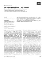
10
2
10
0
10
−2
10
−4
10
−6
Output magnitude
0 5 10 15 20 25 30
Bin
Output spectrum
Errorwithrespecttoexactspectrum
Figure 1: The 32-point Radix-2 FFT of single complex sinusoid in
AWGN, using “16-bit-accuracy” coefficients.
Table 4: Adder-cost (AC) and accuracy of an FFT designed by the
methods in this paper and [1]. (N = FFT length; s c. = scaling type;
acc. = accuracy (bits).)
N
Radix
Sc.
Our methods Methods in [1]
AC Acc. AC Acc.
16 4 U 224 16.1 352 13.0
the new radix-2 design reduces the total adder-cost by 29%
compared to [15]. These gains are due to both the search over
a larger range of rotator structures and the fact that the coef-
ficients are not constrained to coarsely-quantised SOPOT-1
values. If split-radix (2/4) FFTs are used, even lower cost de-
signs are achieved, as shown in Tab le 3. The adder-cost saving
compared to [ 15] increases to 24% for the 32-point FFT, and
46% for the 128-point FFT.
Table 4 presents results for a design to meet the speci-
fications of the length-16 radix-4 design presented in [1].
The design using the methods of this paper has three-bit
greater accuracy than that in [1], with adder-cost reduced
by 36%, and unlike [1] it also has unity gain and no phase
offset.
Table 5 presents results for transform sizes N = 8to256
and target accuracies of 12, 16, and 20 bits. Radix-2 results
are presented for all sizes, and radix-4 results are given for
N = 4
K
only. Split-radix (2/4) designs are presented for N>
16 (for N = 8 or 16 the split-radix design has the same adder-
cost as the radix-2 or radix-4 transform, resp.). In all other
cases a split-radix (2/4) design gave the lowest cost, followed
by a radix-4 design (for N = 4
K
), with r adix-2 designs having
the highest cost. The reduction in adder-cost compared to
the use of CSD multipliers (in an FFT of the same size and
radix) is shown in the final column of Tabl e 5.
The reductions in adder-cost can be attributed to two
factors—first, the effect of the number of rotators due to
Table 5: Adder-cost (AC) and accuracy of various FFTs. (N =
FFT length; sc. = scaling; acc. = accuracy; redn. = %reduction
in AC compared to CSD coefficients.)
N Radix Sc. AC Acc. bits Redn.(%)
82U64 11.96
82U68 18.511
82U72 26.022
16
2 U 216 12.216
4 U 200 12.414
16
2 U 240 16.115
4 U 220 16.014
32
2 C 648 12.220
2/4 U 576 12.218
32
2 U 728 16.020
2/4 U 636 16.119
64
2 C 1684 12.025
4 U 1520 12.221
2/4 C 1412 12.022
64
2 U 1960 16.024
4 U 1696 16.024
2/4 U 1604 16.024
64
2 C 2212 20.54 27
4 C 1900 20.625
2/4 C 1788 20.525
128
2 C 4280 12.120
2/4 C 3380 12.221
128
2 U 4880 16.024
2/4 U 3732 16.019
256
2 C 10376 12.026
4 C 8888 12.024
2/4 C 7604 12.118
256
2 C 11840 16.028
4 U 10224 16.124
2/4 C 8340 16.124
256
2 C 13808 20.529
4 C 11592 20.527
2/4 U 9448 20.526
radix and structure choice, and secondly the result of us-
ing the cost-reduced rotators compared to CSD implemen-
tations. To determine the roles of these two factors, the aver-
age number of adders per rotator was calculated. Apart from
sizes N = 8 and 16, the result was 9.75 ± 0.5 adders per rota-
tor for 12-bit accuracy, 12.25 ± 0.25 for 16 bits, and 15 ± 0.5
for 20 bits. For N = 8 and 16, the values are lower because
the cost of rotation by a multiple of π/4 is lower. Also the ac-
curacies are higher than the number of bits after the binary
point. This is because for b = 8, the fixed-point approxima-
tion of
√
0.5 is 181/256, which has an accuracy of 11.9 bits;
while for b = 16, the fixed-point approximation 46341/2
16
has an accuracy of 18.5 bits.
To illustrate the overall performance of a typical multipli-
erless FFT, the “16-bit-” accuracy 32-point radix-2 FFT (as in
Multiplierless Implementation of Rotators and FFTs 2909
Table 5) was used to compute the spectrum of the signal
x( n) = 20 exp
jπn6
32
+ v(n), n = 1, , 32, (5)
where v(n) is a unit-variance complex Gaussian noise. The
computed spectrum, and the error between it and the exact
spectrum, are shown in Figure 1. The measured signal-to-
noise ratio was 104 dB, in reasonable agreement with the
value 97 dB given by (2) using b = 16.0 bits.
6.4. Discussion
The resulting adder-count for the rotators is typically be-
tween one half and two thirds of the total adder-cost of the
FFT, depending on the required accuracy.
However, these adder-costs may still not be the low-
est that could be achieved. None of the published meth-
ods for reducing adder-cost guarantees optimality, except for
the RAG-n method [6] under certain circumstances. Fur-
ther limitations of the search process described in this paper
(such as the limited search of cascaded rotator implementa-
tions, the limited size of tables for optimum single multipli-
ers, mentioned in Section 5, and the limited U- and C-scaling
strategies) also mean that optimality is not claimed.
This paper concerns only minimisation of the adder-
count. In a VLSI implementation, it might also be desirable
to limit the logic depth [5, 20] (which in this case implies lim-
iting the number of adder delays in the rotator). This c an be
achieved by including the logic depth, with an appropriate
weighting, into the “cost” measure throughout the process.
In a similar way, a weighted cost for binary shifts could be in-
cluded, if these were relevant to a particular implementation.
One way in which length-M multiplierless FFTs could be
used is as core blocks within a radix-M FFT. Conventional
multipliers could then be used for the twiddle factors be-
tween the radix-M units.
Another option would be a completely parallel imple-
mentation of the FFT. For large transform sizes this would
require large area, but it would be capable of extremely high
processing throughput. Alternatively, if used to provide a
more conventional throughput rate of FFTs per unit time,
the circuit might be static (i.e., with no logic transitions oc-
curring) for a large fraction of the time. In a CMOS imple-
mentation where power consumption is very low when a cir-
cuit is not changing its state, this might result in a low-power
(though large area) implementation.
In some implementations the irregular structure of the
split-radix transform is disadvantageous, but in a fully paral-
lel implementation it would be of no disadvantage.
7. CONCLUSIONS
The methods described in this paper allow multiplierless ro-
tators and multiplierless FFTs of arbitrary size and accu-
racy to be designed. We have shown that to minimise ro-
tator adder-cost, it is necessary to consider every form of
rotator described in Section 4 . For FFTs, the most success-
ful approach was based on the use of multiplierless rota-
tors in conventional FFT structures. The application of ma-
trix CSE methods to the fixed-point DFT multiplication did
give equally good results for small transform sizes, but it
took much longer time, and this computational disadvan-
tage was found to increase rapidly with t ransform size and
wordlength. For rotator-based FFT design it is only neces-
sary to investigate PO2 scale factors. Searches are therefore
fast.
The resulting adder-count for the rotators is typically be-
tween one half and two thirds of the total adder-cost of the
FFT, for accuracies of 12–20 bits. For a given accuracy re-
quirement, multiplierless FFTs designed using the methods
in this paper have significantly lower adder-cost than previ-
ously described designs or implementations using conven-
tional CSD coefficients.
As a result, fully or highly parallel VLSI implementations
are feasible. Alternatively, the methods described in this pa-
per could be used to design efficient length-M FFTs for use
in larger radix-M transform processors.
REFERENCES
[1] A. M. Despain, “Very fast Fourier transform algorithms hard-
ware for implementation,” IEEE Trans. Comput.,vol.28,no.5,
pp. 333–341, 1979.
[2] A. G. Dempster and M. D. Macleod, “General algorithms for
reduced-adder integer multiplier desig n,” Electronics Letters,
vol. 31, no. 21, pp. 1800–1802, 1995.
[3] A. G. Dempster and M. D. Macleod, “Constant integer multi-
plication using minimum adders,” IEE Proceedings—Circuits,
Dev ices and Systems, vol. 141, no. 5, pp. 407–413, 1994.
[4] O. Gustafsson, A. G. Dempster, and L. Wanhammar, “Ex-
tended results for minimum-adder constant integer multipli-
ers,” in Proc. IEEE International Symposium on Circuits and
Systems (ISCAS ’02), vol. 1, pp. 73–76, Scottsdale, Ariz, USA,
May 2002.
[5] R. I. Hartley, “Sub-expression sharing in filters using canonic
signed digit multipliers’,” IEEE Trans. Circuits Syst. II, vol. 43,
no. 10, pp. 677–688, 1996.
[6] A. G. Dempster and M. D. Macleod, “Use of minimum-adder
multiplier blocks in FIR digital filters,” IEEE Trans. Circuits
Syst. II, vol. 42, no. 9, pp. 569–577, 1995.
[7] M. Potkonjak, M. B. Srivastava, and A. Chandrakasan, “Multi-
ple constant multiplications: efficient and versatile framework
and algorithms for exploring common sub-expression elimi-
nation,” IEEE Trans. Computer-Aided Design,vol.15,no.2,
pp. 151–165, 1996.
[8]R.Pasko,P.Schaumont,V.Derudder,S.Vernalde,andD.
Durackova, “A new algorithm for elimination of common
sub-expressions,” IEEE Trans. Computer-Aided Design, vol. 18,
no. 1, pp. 58–68, 1999.
[9]M.D.MacleodandA.G.Dempster,“Commonsub-
expression elimination algorithm for low-cost multiplierless
implementation of matrix multipliers,” Electronics Letters,
vol. 40, no. 11, pp. 651–652, 2004.
[10] J. Liang and T. D. Tran, “Fast multiplierless approximations of
the DCT with the lifting scheme,” IEEE Trans. Signal Process-
ing, vol. 49, no. 12, pp. 3032–3044, 2001.
[11] A. C. Zelinski, M. P
¨
uschel, S. Misra, and J. C. Hoe, “Auto-
matic cost minimization for multiplierless implementations
of discrete signal transforms,” in Proc. IEEE International
2910 EURASIP Journal on Applied Signal Processing
Conference on Acoustics, Speech, and Signal Processing (ICASSP
’04), vol. 5, pp. 221–224, Montreal, Quebec, Canada, May
2004.
[12] M. D. Macleod, “Multiplierless Winograd and prime factor
FFT implementation,” IEEE Signal Processing Lett., vol. 11,
no. 9, pp. 740–743, 2004.
[13] P. Duhamel and H. Hollmann, “Split radix FFT algorithm,”
Electronics Letters, vol. 20, no. 1, pp. 14–16, 1984.
[14] W. A. Perera and P. J. W. Rayner, “Optimal design of discrete
coefficient DFTs for spectral-analysis: extension to multiplier-
less FFTs,” IEE Proceedings—G: Circuits, Devices and Systems,
vol. 133, no. 1, pp. 8–18, 1986.
[15] S. C. Chan and P. M. Yiu, “An efficient multiplierless approxi-
mation of the fast Fourier transform using sum-of-powers-of-
two (SOPOT) coefficients,” IEEE Signal Processing Lett., vol. 9,
no. 10, pp. 322–325, 2002.
[16] M. D. Macleod and A. G. Dempster, “Multiplierless FIR filter
design algorithms,” IEEE Signal Processing Lett., vol. 12, no. 3,
pp. 186–189, 2005.
[17] D. R. Bull and D. H. Horrocks, “Primitive operator digi-
tal filters,” IEE Proceedings—G: Circuits, Devices and Systems,
vol. 138, no. 3, pp. 401–412, 1991.
[18] A. M. Despain, “Fourier transform computers using CORDIC
iterations,” IEEE Trans. Comput., vol. 23, no. 10, pp. 993–1001,
1974.
[19] A. V. Oppenheim and C. J. Weinstein, “Effects of finite register
length in digital filtering and the fast Fourier transform,” Proc.
IEEE, vol. 60, no. 8, pp. 957–976, 1972.
[20] A. G. Dempster, S. S. Dimirsoy, and I. Kale, “Designing multi-
plier blocks with low log ic depth,” in Proc. IEEE International
Symposium on Circuits and Systems (ISCAS ’02), vol. 5, pp.
773–776, Scottsdale, Ariz, USA, May 2002.
Malcolm D. Macleod was born in Cathcart,
Glasgow, Scotland, in 1953. He was awarded
the B.A. (with distinction) and M.A. degrees
in electrical sciences, and the Ph.D. degree
in digital signal processing, by the Univer-
sity of Cambridge, England, in 1974, 1978,
and 1979, respectively. From 1978 to 1988
he worked for Cambridge Consultants Ltd.
on a wide range of signal processing, elec-
tronics, and software projects. From 1988 to
1995 he was a Lecturer in signal processing and communications
in the Engineering Department of Cambridge University, and from
1995 to 2002 he was the Director of Research in the department.
In 2002, he joined QinetiQ Ltd. as a Senior Research Scientist. He
is a Fellow of the IEE (UK). He has published over 80 papers and
conference papers, and contributed chapters to several books. His
main research interests are in digital filter design, algorithms and
architectures for DSP, nonlinear filtering, adaptive filtering, opti-
mal detection, high-resolution spectrum estimation, beamforming
and direction finding, and applications in sonar, radar, audio, in-
strumentation, and communication systems.