Báo cáo hóa học: " A Novel High-Speed Configurable Viterbi Decoder for Broadband Access" doc
Bạn đang xem bản rút gọn của tài liệu. Xem và tải ngay bản đầy đủ của tài liệu tại đây (627.47 KB, 11 trang )
EURASIP Journal on Applied Signal Processing 2003:13, 1317–1327
c
2003 Hindawi Publishing Corporation
A Novel High-Speed Configurable Viterbi
Decoder for Broadband Access
Mohammed Benaissa
Department of Electronic and Electrical Engineering, The University of Sheffield, Mappin Street, Sheffield S1 3JD, UK
Email: m.benaissa@sheffield.ac.uk
Yiqun Zhu
Department of Electronic and Electrical Engineering, The University of Sheffield, Mappin Street, Sheffield S1 3JD, UK
Email: elp99yz@sheffield.ac.uk
Received 31 January 2003 and in revised form 11 September 2003
A novel design and implementation of an online reconfigurable Viterbi decoder is proposed, based on an area-efficient add-
compare-select (ACS) architecture, in which the constraint length and traceback depth can be dynamically reconfigured. A design-
space exploration to trade off decoding capability, area, and decoding speed has been performed, from which the maximum level
of pipelining against the number of ACS units to be used has been determined while maintaining an in-place path metric updating.
An example design with constraint lengths from 7 to 10 and a 5-level ACS pipelining has been successfully implemented on a Xilinx
Virtex FPGA device. FPGA implementation results, in terms of decoding speed, resource usage, and BER, have been obtained using
a tailored testbench. These confirmed the functionalit y and the expected higher speeds and lower resources.
Keywords and phrases: pipelining, configurable, ACS, area-efficient architecture, design-space exploration, s chedule.
1. INTRODUCTION
Overcoming the variable deterioration in the reliability of a
broadband communication channel in real time is a critical
issue. That is why channel-coding techniques such as convo-
lutional codes represent an important part of any broadband
communication system. For example, DSL, WLAN, and 3G
standards all require variations of convolutional coding with
differing coding performance (constraint length and code
rate) at differing data rates and therefore require differing
decoding performance, usually using Viterbi decoding [1].
Therefore, from the viewpoint of channel-coding techniques,
this demands both high decoding speed and variable decod-
ing capability to match the channel conditions. Furthermore,
it is becoming increasingly important to develop hardware
implementations that can operate over a range of standards
and can support multiple networks without redesign. Hence
both hardware performance and flexibility are crucial. This
requires high-speed, low-power dynamically reconfigurable
forward error control coding dedicated hardware architec-
tures that can operate within a range of channel conditions
under a number of speed/power performance constraints at
different time intervals.
Designing and implementing such architectures is a chal-
lenging problem for large constraint lengths Viterbi de-
coders since decoding capability and decoding complexity
are closely related to the constraint length used. A larger con-
straint length can offer a higher decoding capability but at
the expense of a higher decoder complexity, often in terms
of a cost function of resource usage versus decoding delay
versus decoding capability, depending on the specific hard-
ware architecture adopted. A useful Viterbi decoder architec-
ture will therefore offer the flexibility to trade off the param-
eters of this cost function with reasonable performance. This
requires architectural level decisions to allow optimum re-
source sharing and maximum pipelining to achieve a prac-
tical compromise between resource usage and decoding per-
formance for a range of constraint lengths. Such architectural
decisions would range from state-parallel to state-serial ar-
chitectures. On the one hand, a state-parallel architecture,
in which the number of ACSs is equal to the number of
states and all ACSs operate in parallel, can offer high decod-
ing speed, which only depends on the computation delay of
the ACS feedback loop. However, the hardware complexity
increases exponentially with the constraint length of the con-
volutional codes and this makes these architectures often un-
suitable for applications requiring codes with large constraint
lengths such as 3G (constraint length 9). On the other hand,
in a state-serial architecture (sometimes referred to as soft-
ware solutions), all states share one ACS; although flexible,
1318 EURASIP Journal on Applied Sig nal Processing
such architecture would result in a huge decoding delay for
large constraint lengths, hence limited throughput to suit
most broadband applications. An area-efficient/foldable ar-
chitecture as proposed in [2, 3, 4, 5] uses more than one
ACS. The number of ACSs to be used depends on the require-
ment of resource usage, and as such this class of architectures
is attractive for a configurable implementation solution for
large constraint lengths without excessive penalties in terms
of resource usage. However, their speed performance suffers
when the ratio of number of states to number of ACS units
increases. Therefore, such architectures would only be possi-
ble for broadband access performance if their design space is
explored in terms of maximum speedup (pipelining) versus
number of ACS units (area) versus constraint length (decod-
ing capability).
In this paper, we investigate the design space for area-
efficient Viterbi decoders and develop an online reconfig-
urable architecture that will support a range of constraint
lengths without an excessive loss of speed performance.
A scheduling program is used to systematically determine
the maximum level of pipelining (speedup) that can be ap-
plied to the decoder in an area-efficient/foldable architecture
with in-place path metric updating [6]. This enables the ex-
ploration of the trade-off of decoding speed (throughput)
versus area (number of ACS units) for a range of constraint
lengths.
This exploration is undertaken for a range of con-
straint lengths from 7 to 10 selected to cover many broad-
band access applications and also this range is challenging
enough in terms of complexity to validate the design ap-
proach adopted. The optimum solution in terms of through-
put versus area versus decoding capability (which is lim-
ited here by constraints 7 to 10) yielded a maximum level
of pipelining of 5 levels for an area-efficient architecture
with 8 ACS units using in-place path metric updating. This
gives a speedup of 5 times on designs using a similar area-
efficient/foldable architecture and achieves 5/8 the speed
of a state-parallel architecture. The speed/throughput of
course is determined by the requirements of the lowest con-
straint length, in this case, 7. In addition to the in-place
updating, pipelining also enables reduction in path metric
memory by allowing lower bit resolution for the computa-
tions.
The design is then implemented on a Virtex FPGA and
tested using a de veloped hardware testbench. Actual hard-
ware performance figures and BER curves are obtained to
confirm the functionality and performance improvements.
It is important to note that Viterbi decoders have been
widely investigated and implementations of configurable de-
coders have been reported in many papers. For example,
[7] implemented an adaptive Viterbi decoder (AVD) based
on reconfigurable processor board (RCPB), in which the
constraint lengths can be reconfigured from 7 to 15. The
AVD is specifically designed for an FPGA platform by us-
ing the features of FPGA configuration, so it is not suit-
able for the application where instant online reconfigura-
tion is required due to the very low-speed FPGA config-
uration. In [8], a reconfigurable Viterbi decoder architec-
Table 1: 3D design exploration of area-efficient Viterbi decoders.
States/ACS units (N/P)12481632
ACS pipeline levels 1 1 2 5 10 20
Throughput/speed (Mbps) FF/2 F/25F/85F/85F/8
ture, the constraint lengths which can be reconfigured from
3 up to 7, was proposed by adopting a state-parallel ACS
module. Because the hardware complexity of state-parallel
ACS architectures is exponentially proportional to the con-
straint length, this approach is not suitable for large con-
straint lengths.
To our knowledge, the approach adopted in this paper,
the level of performance improvements, and the trade-offs
achieved have not been reported before.
The paper is organised as follows. A brief design-space
exploration is given in Section 2. The architecture of a con-
figurable Viterbi decoder example is described in Section
3. FPGA implementations and performance comparisons
based on the FPGA prototype are given in Section 4.Com-
parisons and conclusions are presented in Sections 5 and 6,
respectively.
2. DESIGN-SPACE EXPLORATION FOR
AREA-EFFICIENT ARCHITECTURES
As already mentioned in the introduction, the trade-off area
versus speed versus decoding capability is crucial in a re-
configurable area-efficient/foldable Viterbi architecture. In
our case, decoding capability corresponds to the constraint
length, area corresponds to the number of ACS units used,
and speed corresponds to the throughput achieved, which
can be assimilated in this case to the number of pipeline lev-
els that can be inserted in the ACS feedback loop.
A software program was written to explore this 3D de-
sign space in order to determine an optimum solution while
maintaining a standard resource saving techniques known as
in-place path metric update. The results are shown in Tabl e 1 .
A number of interesting observations can be made at
this stage. The first column of course refers to a state-
parallel architecture (N = P), w hich achieves the best speed/
throughput that we note as F (Mbps), for example. The sec-
ond and third columns show that halving the number of ACS
units (P = N/2) is the worst solution as it does not give any
speedup (pipelining) advantage. In fac t we can achieve the
same throughput rate of F/2 by using a 2-level pipelining of
the ACS feedback loop on a quarter of the number of ACS
units (P = N/4). This corresponds to a speedup by a factor of
2. The extreme case of the last column shows that a through-
put rate of 5F/8 can, in theory, be maintained on a number
of ACS units P = N/32 as long as we can insert 20 levels of
pipelining. Of course pipeline balancing is a critical issue in
this case and adopting such a solution in practice would not
be advisable.
The optimum solution from a practical hardware im-
plementation viewpoint is the fourth column which corre-
sponds to using a number of ACS units P = N/8. This gives a
A Novel High-Speed Configurable Viterbi Decoder for Broadband Access 1319
Table 2: 120 2-bit index data arrangement in each ROM (128 × 2).
Constraint length (K )— 7 8 9 10
ROM address 0–7 8–15 16–31 32–63 64–127
5 times speedup by inserting judiciously 5 levels of pipelining
in the ACS feedback loop; often some careful timing analy-
sis is required here. For a configurable design for constraint
lengths from 7 to 10, this optimum solution translates to
64/8 = 8 ACS units with 5 levels of pipelining. The max-
imum throughput is governed by the requirements of con-
straint length 7.
The next section explains in detail the issues involved in
the context of a design example.
3. CONFIGURABLE VITERBI DECODER
ARCHITECTURE
A reconfigurable Viterbi decoder, which is based on an area-
efficient ACS architecture, is composed of a branch metric
(BM) module, an ACS module, a best-state module, and a
traceback module.
3.1. BM module
TheBMmoduleistogeneratetheBMs[9] for the proper
butterfly (BF) units in the ACS module at the proper time
unit. For our configurable Viterbi decoder, considering the
whole range of constraint lengths 7, 8, 9, and 10, there are
480 possible different BF operations, in which 32, 64, 128,
and 256 BF operations are needed for constraint lengths 7,
8, 9, and 10, respectively. Each different BF operation needs
2-bit index data to identify its corresponding BM from 4 pos-
sible BMs. On the other hand, all the 480 BF operations are
equally distributed for four available BF units, each BF unit
is responsible for 120 possible differ ent BF operations. As a
result, 120 2-bit index data are required for each BF unit to
select proper BMs for 120 possible BF operations. Hence the
BM module can be configured to provide BMs for one spe-
cific constraint length from the constraint lengths from 7 to
10.
To be easily implemented, a ROM (128 × 2) is used to
store the 120 2-bit index data needed for each BF unit. For
each ROM, the 120 2-bit index data are arranged as shown in
Table 2 as this allows for easy hardware implementation. The
first 8 addresses (0 to 7) are not used, and then 8 addresses (8
to 15), 16 addresses (16 to 31), 32 addresses (32 to 63), and
64 addresses (64 to 127) are used for constraint lengths 7, 8,
9, and 10, respectively.
3.2. ACS module
In the proposed architecture, this module is the most critical
part, in which a novel ACS pipeline scheme is implemented
to achieve higher ACS computation speed. To better describe
the ACS pipeline scheme, we consider the case of constraint
length 7, so the number of states is 64. Assume that the num-
2i +1i +32
2ii
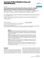
Figure 1: The diagram of BF unit.
ber of available ACS units is 8. The key feature of the pro-
posed ACS pipeline scheme is to speed up ACS operations by
inserting the maximum number of ACS pipeline levels.
For the purpose of simplification, BF units, rather than
ACS units, are used to explain the proposed scheme. The di-
agram of BF unit is illustrated in Figure 1. Each BF unit con-
sists of two ACS units that share the same input and out-
put states. More specifical ly, for each BF, the path metrics for
two current states are obtained from the current BMs and
the path metr ics of two previous states, which lead to current
states by executing two ACS operations.
The overall architecture of the ACS module is shown in
Figure 2. BF0, BF1, BF2, and BF3 are BF units. There are 4
BF units, which make up 8 ACS units as used in our area-
efficient ACS module. Switch0 and Switch1 are 4×4 switches,
the function of which, as given in Tab le 3, is to permute the
path metric network in such a way that the global routing
network can be localized by these regular bus-switch com-
ponents. Different from [10], in order to have an identi-
cal simplified architecture for all BF units, a 4 × 4switchis
used instead of two 2 × 2 switches. DpRAM0 to DpRAM7
are dual port RAMs used for path metric memory. With in-
place path metric updating, the required path metric mem-
ory size is equal to the number of path metrics, which is the
same as the number of states (there are 64 states for our
case). So the depth of each path metric memory DpRAM
is 8.
The initial arrangement of all the 64 path metrics in the
path metric memory is given at iteration 0 in Ta ble 4,in
which the state number is used to denote the correspond-
ing path metric. For instance, the path metric of state 2D
is assigned into dual-port memory DpRAM1 at address 5,
and will be the output to BF0 as PmIn01 for ACS computa-
tion. Following the architecture of the ACS module shown in
Figure 2, with proper selection control as shown in Table 3,
the state distribution at iteration 1 can be obtained from iter-
ation 0 after 8 cycles by executing in-place path metric updat-
ing. Each iteration takes 8 cycles and the initial arrangement
of the state of path metrics in DpRAM is re-established after
6 iterations in terms of the property of in-place path metric
updating technique [6]. Only iterations 0 and 1 are given in
Table 4, in which we can see that due to in-place path metric
updating, the path metric distributions are different between
iterations 0 and 1.
1320 EURASIP Journal on Applied Sig nal Processing
SEL
PmIn31
BF3
PmOut31
DpRAM7In
DpRAM7
PmIn31
PmIn30 PmOut30
DpRAM5In
DpRAM5
PmIn21
PmIn11
BF1
PmOut11
DpRAM3In
DpRAM3
PmIn11
PmIn10 PmOut10
Switch1
DpRAM1In
DpRAM1
PmIn01
SEL
PmIn21
BF2
PmOut21
DpRAM6In
DpRAM6
PmIn30
PmIn20 PmOut20
DpRAM4In
DpRAM4
PmIn20
PmIn01
BF0
PmOut01
DpRAM2In
DpRAM2
PmIn10
PmIn00
Switch0
PmOut00
DpRAM0In
DpRAM0
PmIn00
Figure 2: The architecture of the ACS module.
Table 3: Selection control for Switch0 and Switch1.
SEL00011011
DpRAM0In PmOut00 PmOut01 PmOut20 PmOut21
DpRAM2In PmOut20 PmOut21 PmOut00 PmOut01
DpRAM4In PmOut01 PmOut00 PmOut21 PmOut20
DpRAM6In PmOut21 PmOut20 PmOut01 PmOut00
DpRAM1In PmOut10 PmOut11 PmOut30 PmOut31
DpRAM3In PmOut30 PmOut31 PmOut10 PmOut11
DpRAM5In PmOut11 PmOut10 PmOut31 PmOut30
DpRAM7In PmOut31 PmOut30 PmOut11 PmOut10
Obviously, address scrambling is required for in-place
path metric updating to be executed, in other words, address
scrambling is used to schedule the right path metric into the
right cycle in order for the same set of path metrics to be
read into BF units for ACS operation at the same cycles of
any iteration. There are many different address scrambling
methods, all of which can meet the requirements of in-place
path metric updating. However, besides in-place path met-
ric updating scheme, another requirement of address scram-
bling is that the maximum number of pipeline levels can be
obtained without any impact of in-place path metr ic updat-
ing. For further discussion, we consider two specific address
scrambling methods as shown in Tabl e 5 in which only the
first two iterations are given.
For Address scrambling 1, for any path metric memory,
the path metric is read from address i at cycle i of iteration 0,
where i is from 0 to 7. At iteration 1, for path metric mem-
ory, DpRAM0 to DpRAM3, the path metrics are read from
addresses0,2,4,6,1,3,5,and7atcycles0,1,2,3,4,5,6,
and 7, respectively, while for DpRAM4 to DpRAM7, the path
Table 4: State arrangement and in-place path metric updating.
Iteration 0
Address (DpRAM0–7) 012 345 67
BF0
DpRAM0 00 04 02 06 09 0D 0B 0F
DpRAM1 20 24 22 26 29 2D 2B 2F
BF1
DpRAM2 10 14 12 16 19 1D 1B 1F
DpRAM3 30 34 32 36 39 3D 3B 3F
BF2
DpRAM4 08 0C 0A 0E 01 05 03 07
DpRAM5 28 2C 2A 2E 21 25 23 27
BF3
DpRAM6 18 1C 1A 1E 11 15 13 17
DpRAM7 38 3C 3A 3E 31 35 33 37
Iteration 1
Address (DpRAM0–7) 012 345 67
BF0
DpRAM0 00 09 04 0D 02 0B 06 0F
DpRAM1 20 29 24 2D 22 2B 26 2F
BF1
DpRAM2 10 19 14 1D 12 1B 16 1F
DpRAM3 30 39 34 3D 32 3B 36 3F
BF2
DpRAM4 01 08 05 0C 03 0A 07 0E
DpRAM5 21 28 25 2C 23 2A 27 2E
BF3
DpRAM6 11 18 15 1C 13 1A 17 1E
DpRAM7 31 38 35 3C 33 3A 37 3E
metricsarereadfromaddresses1,3,5,7,0,2,4,and6at
cycles 0, 1, 2, 3, 4, 5, 6, and 7, respectively. By address scram-
bling, at any iteration, the same path metrics will be read out
at the same cycles as in the first iteration. For example, at cy-
cle 4 of any iteration, the path metrics of state 09, 29, 19, 39,
01, 21, 11, and 31 must be read from the path metric memory
into 4 BF units, BF0, BF1, BF2, and BF3. After the multiplex-
ing of the two switches, Switch0 and Switch1, the output path
A Novel High-Speed Configurable Viterbi Decoder for Broadband Access 1321
Table 5: Two address scrambling methods of path metric memory.
Cycle 01234567
Address scrambling 1
SEL 00 01 00 01 10 11 10 11
Iteration 0
Address (DpRAM0–3) 01234567
Address (DpRAM4–7) 01234567
Iteration 1
Address (DpRAM0–3) 02461357
Address (DpRAM4–7) 13570246
Address scrambling 2
SEL 00 01 00 10 01 11 10 11
Iteration 0
Address (DpRAM0–3) 01243567
Address (DpRAM4–7) 01243567
Iteration 1
Address (DpRAM0–3) 02416357
Address (DpRAM4–7) 13507246
Table 6: The allowed cycles for ACS for address s crambling 1.
Cycle 01234567
Theallowedcycles87766554
Table 7: The allowed cycles for ACS for address s crambling 2.
Cycle 01234567
Theallowedcycles87775565
metrics of state 02, 22, 12, 32, 03, 23, 13, and 33 will be writ-
ten back to the path metric memory w ith the same address.
From Tables 3 and 4, we can see that the output path metrics
of state 02, 22, 12, and 32 will not be read until 6 cycles later,
while the output path metr ics of state 03, 23, 13, and 33 will
not be read until 10 cycles later. Therefore, 6 cycles can be
allowed for the ACS computations of the fourth cycle path
metrics. In other words, 6 cycles can be available for the ACS
computations of the path metrics read out at cycle 4 without
any impacts on in-place path metric updating. Likewise, at
any other cycle, the number of cycles allowed from the cor-
responding ACS computation can be worked out, which is
given in Ta ble 6.
From the point of view of the entire ACS module, with
address scrambling 1, 4 cycles are available for the ACS com-
putation, in other words, 4 pipeline levels can be inserted into
ACS feedback loop to speed up ACS computation.
By applying the same method to address scrambling 2,
which is obtained from the address scrambling 1 by swap-
ping the addresses between cycles 3 and 4, the corresponding
allowed cycles for ACS are obtained as in Ta ble 7.Asaresult
of address scrambling 2, 5 pipeline levels can be available for
ACS operations.
Table 8: The maximum pipeline levels for constraint lengths from
7 to 10 with the usage of 8 ACS units.
Constraint length (K )7 8 9 10
ACS pip eline levels 5 10 20 40
From the above discussion, for our area-efficient ACS
module with constraint length 7 and the area saving require-
ment of 8 ACS units, at least 5 pipeline levels can be intro-
duced for the ACS operation. However, by using exhaustive
computer search, we found that 5 is the maximum number
of pipeline levels which can be introduced for the above area-
efficient ACS module.
With the usage of 8 ACS units, the maximum number of
ACS pipeline levels can be worked out for constraint lengths
from7to10asshowninTable 8.
Therefore, in order to implement our ACS module, in
which constraint length can be reconfigurable from 7 to 10
with the restr iction of 8 ACS units, 5 ACS pipeline levels can
be inserted into ACS feedback loop.
To reduce the delay of the ACS computational loop, two’s
complement arithmetic [11] i s normally used for implicit
renormalization of the path metrics. Furthermore, in order
to enable modulo nor malization of the path metrics, accord-
ing to [12, 13], the minimum resolution of the path metrics
is g iven by
∆
max
= λ
max
log
2
N,
Γ
bits
=
log
2
∆
max
+ kλ
max
+1,
(1)
where N is the number of states, λ
max
is maximum BM, and
k is 1 and 2 for radix-2 ACS and radix-4 ACS, respectively.
Hence, for a maximum constraint length 10 and radix-2 ACS
with 3-bit quantisation, N = 512, k = 1, and λ
max
= 14;
thus 1 gives a minimum resolution of the path metrics of 9
bits. In other words, at least 9-bit data width is required for
path metric memory in order to use modulo normalization
for the path metrics. However, in our reconfigurable Viterbi
decoder, the 5-level ACS pipeline scheme allows a modified
variable shift path metric normalization [12]andsaturation
protection circuits to be inserted into the ACS feedback loop
in a pipeline fashion. This allows even lower resolution to
be used for the path metric without decoding performance
loss. The modified variable shift path metric normalization
is realized by subtracting a constant value from all path met-
rics, if all path metrics is greater than this constant value,
rather than subtracting the minimum path met ric from all
path met rics. Hence, no operation of minimum path met-
ric selection is required in our modified variable shift path
metric normalization. Saturation protection circuit, which
is used to avoid catastrophic overflow, is implemented by
setting the maximum value for any overflow path metrics.
With our modified variable shift path metric normalization
and saturation protection scheme, a 6-bit path metric is
sufficient for the path metric computation in the proposed
1322 EURASIP Journal on Applied Sig nal Processing
reconfigurable Viterbi decoder, without suffering from a de-
coding performance penalty. Therefore, 33% reduction of
path metric memory usage has been achieved, compared
with the case of modulo nor malization of the path met-
rics. In [5], a 12-bit path metric was used for adequate res-
olution, however, with path metric rescaling and saturation
protection, and the 6-bit path metric was used for the path
metric computation in the proposed configurable Viterbi
decoder without suffering from a decoding performance
penalty. Therefore, another 50% reduction of path metric
memory usage has been achieved compared w ith the case
of [5].
3.3. Best-state module
There are two solutions of traceback in a Viterbi decoder,
best state and fixed state. In a best-state solution, the best-
state survivor path is found for traceback operation, while
in a fixed-state solution the survivor path of any state, usu-
ally state 0, is used for tracing back. An in-depth discussion
of decoding performance for best-state and fixed-state solu-
tions has been addressed in [14]. It is shown that, for com-
parable performance, the traceback depth of the fixed-state
solution is as roughly twice as that of the best-state solution.
As we know, the size of the survivor memory is proportional
to the traceback depth, and a larger traceback depth results
in more memory usage. Therefore, the survivor memory us-
age of a fixed-state solution can be twice that of a best-state
solution. Generally, a fixed-state decoding is only employed
when it is expensive to find the best state such as in the case
of a state-parallel architecture with a large constraint length.
For our reconfigurable Viterbi decoder, because only 8 ACS
are in parallel, only 7 units compare-select (CS) are used to
pick out the best state in which only a 3-cycle extra initial
delay is introduced. The best-state module consists of 7 CS
units working in pipeline to find the best state for the trace-
back module to execute the best-state traceback. Therefore,
the hardware overhead for the best-state solution is signifi-
cantly low.
3.4. Traceback module
In configurable traceback module, a dual-port RAM-based
survivor memory is used to perform the traceback operation.
Considering 8 ACS units in parallel, each ACS unit outputs
one survivor information bit and 8-bit dual-port RAM data
width is used to simplify interfacing between surv ivor mem-
ory and 8 parallel ACS units. In order for the ACS opera-
tions to be time-efficient which demands that no ACS be idle
at any time, traceback must be executed in such a way that
no overflow will take place for the 8-bit survivor data stream
from the ACS module. In other words, traceback module and
ACS module must operate in a pipeline fashion at the same
throughput rate. To be a time-efficient implementation, for
our reconfigurable Viterbi decoder, the overall throughput
rateshavetobe1/8, 1/16, 1/32, and 1/64 bit/cycle for con-
straint lengths 7, 8, 9, and 10 because all states are scheduled
into 8 , 16, 32, and 64 cycles for constraint lengths 7, 8, 9, and
10, respectively.
Table 9: Time-efficient schedule for one traceback.
Constraint length ACS (cycles) Traceback (cycles) Decoded bits
7
128
2(TB
a
+15) 16
82(TB+7)8
92(TB+3)4
10 2(TB + 1) 2
a
TB is traceback depth.
We consider the case of constraint length 7 to figure out
how to design a configurable traceback module to meet the
overall throughput rate (1/8 bit/cycle). Generally, a traceback
depth of five times constraint length is needed for the best-
state traceback, and hence for constraint length 7, the re-
quired traceback depth is 35. Furthermore, in order to match
the hig h-speed clock of the area-efficient ACS module, track-
back module needs to be speeded up by scheduling 2 cy-
cles into each traceback step. Therefore, at least 70 cycles
are required to finish one traceback operation. It is sched-
uled in our reconfigurable Viterbi decoder that one traceback
operation is executed for every 16 iterations of ACS opera-
tion. Because each iteration contains 8 cycles for constraint
length 7, 128 cycles are available for one traceback operation,
while 100 cycles, which is calculated from (35 + 15) × 2, are
needed to retrieve 16 decoded bits at each traceback oper-
ation. In this way, time-efficient decoding can be achieved
since the number of cycles needed for each traceback op-
eration is less than that of 16 iterations. Obviously, if it is
highly desirable to minimise the initial decoding delay, we
can schedule one traceback operation every 12 iterations.
This also meets the requirement of a time-efficient imple-
mentation as the number of cycles for 12 ACS iterations,
12 × 8, is still greater than (35 + 11) × 2 cycles w hich are
needed to retrieve 12 decoded bits. The only drawback is a
more complicated hardware architecture because 12 is not
a value with the form of 2
n
. By using the same method,
time-efficient traceback schedule can be worked out as in
Table 9.
To work out the requirement of a survivor memory size
for our configurable Viterbi decoder, we have to consider
the largest survivor memory usage which should occur at
constraint length 10. Because one traceback operation is
scheduled every 16 ACS iterations and the traceback depth
is required not to be less than 50 for constraint length 10,
50 × 64 × 8 bits are needed to reserve for 50 traceback steps
to retrieve 2 decoded bits which take 102 cycles to finish
the traceback operation. To achieve nonstop ACS operation,
an extra 102 × 8 bits are needed to buffer the new survivor
data from the ACS module during the traceback operation.
Therefore, the overall memory required is 50×64×8+102×8
bits equaling to 3302 × 8 bits. After rounding up to binary
border, we use a dual-por t RAM (4096× 8) as survivor mem-
ory.
It can be calculated from Table 9 that the maximum
traceback depths are 49, 57, 61, and 63 for constraint lengths
7, 8, 9, and 10, respectively. For our FPGA prototype, due to
A Novel High-Speed Configurable Viterbi Decoder for Broadband Access 1323
Table 10: Data format in survivor memory for constraint length 7.
State
Address
Data
01234567
Bit0 00 08 04 0C 12 1A 16 1E
Bit1 01 09 05 0D 13 1B 17 1F
Bit2 20 28 24 2C 32 3A 36 3E
Bit3 21 29 25 2D 33 3B 37 3F
Bit4 10 18 14 1C 02 0A 06 0E
Bit5 11 19 15 1D 03 0B 07 0F
Bit6 30 38 34 3C 22 2A 26 2E
Bit7 31 39 35 3D 23 2B 27 2F
the survivor memory restriction (4096 × 8), the maximum
traceback depth is 62 rather than 63 for constraint length 10.
Before going into the details of the architecture of the
configurable traceback SP module, we star t with the data for-
mat in survivor memory because the traceback logic is de-
cided by the survivor data format in the survivor memory.
The input data bus of DpRAM is connected to the survivor
data that outputted from BF units in ACS module. From Ta-
bles 4 and 5, we know that, in area-efficient ACS module, ad-
dresses are swapped between cycles 3 and 4 to maximise the
speed of ACS computation by inserting 5 pipeline le vels into
ACS loop. In order to simplify the hardware architecture of
the traceback operation, address exchange between cycles 3
and 4, which cancels the address-swapping operation in ad-
dress scrambling in Tabl e 5 , is employed before writing into
survivor memory DpRAM.
To better explain the traceback logic of the configurable
traceback SP module, we start by considering constraint
length 7. Survivor data generated in each ACS iteration are
8× 8 bits which occupy 8 address entries in survivor memory,
and survivor memory receives survivor data for ACS module
iteration by iteration and stores the survivor data one itera-
tion after another. As we know, a 12-bit address is required
to access all data in DpRAM (4096 × 8). Obviously, the low
3-bit address is used to access data within one iteration and
the high 9-bit address is used to identify iteration number.
Table 10 shows the resulting survivor data arrangement in
DpRAM. Because the data format is the same for any iter-
ation, Table 10 only gives the data arrangement for one iter-
ation.
Let I be a 9-bit iteration number, let C be the low 3-bit
address of the 12-bit survivor memory address, and let R be
3-bit index of 8-bit data in surv ivor memory. So any survivor
bit in survivor memory can be identified by I, C,andR.In
addition, let V be the survivor bit value with the correspond-
ing I, C,andR. In order for traceback logic to be clearly de-
scribed, I, C, R,andV are packed together and are called
traceback packet in Figure 3.
Obviously, with the current traceback packet informa-
tion (I, C, R,andV), the previous traceback packet can be
obtained from the trellis diagram of Viterbi algorithm. By
I8 I7 I6 I5 I4 I3 I2 I1 I0 C2 C1 C0 R2 R1 R0 V
ICR
Figure 3: Traceback packet for constraint length 7.
checking all states, traceback formulas can be deduced a s
R2
prv
R1
prv
R0
prv
=
R1
cur
⊕ C1
cur
VC2
cur
, (2)
C2
prv
C1
prv
C0
prv
= C1
cur
C0
cur
R2
cur
⊕ C2
cur
, (3)
I
prv
= I
cur
− 1, (4)
where the subscripts prv and cur denote the previous and
current traceback steps.
Equation (4) is quite obvious because the iteration is sim-
ply updated by reducing one for each traceback step. Using
an example to verify (2)and(3) assuming that the current
state is 03 and the corresponding survivor bit value is “1,” it
can be seen from Table 10 that the corresponding current R
and C are “101” and “100,” respectively. Using (2)and(3),
the corresponding previous R and C can be calculated as fol-
lows:
R2
prv
R1
prv
R0
prv
= (R1
cur
⊕ C1
cur
)VC2
cur
= (0 ⊕ 0)11 = 011,
C2
prv
C1
prv
C0
prv
= C1
cur
C0
cur
(R2
cur
⊕ C2
cur
)
= 00(1 ⊕ 1) = 000.
(5)
So the corresponding previous state is 21. On the other hand,
it can be seen from the trellis diagram of Viterbi algorithm
that, with survivor bit value 1, the state previous to state 03
is state 21. It is the same as that in (2)and(3).
Therefore, (2), (3), and (4) completely govern the trace-
back operation for constraint length 7. By using the same
method, the traceback formulas for constraint lengths 8, 9,
and 10 can be deduced as (6)to(12). Figure 4 shows the cor-
responding traceback packets for constraint lengths 8, 9, and
10.
For constraint length 8,
R2
prv
R1
prv
R0
prv
=
R1
cur
⊕ C2
cur
VC3
cur
, (6)
C3
prv
C2
prv
C1
prv
C0
prv
= C2
cur
C1
cur
C0
cur
R2
cur
⊕ C3
cur
,
(7)
I
prv
= I
cur
− 1. (8)
For constraint length 9,
R2
prv
R1
prv
R0
prv
=
R1
cur
⊕ C3
cur
VC4
cur
,
C4
prv
C3
prv
C2
prv
C1
prv
C0
prv
= C3
cur
C2
cur
C1
cur
C0
cur
R2
cur
⊕ C4
cur
,
I
prv
= I
cur
− 1.
(9)
1324 EURASIP Journal on Applied Sig nal Processing
I7 I6 I5 I4 I3 I2 I1 I0 C3 C2 C1 C0 R2 R1 R0 V
ICR
Constraint length 8
I6 I5 I4 I3 I2 I1 I0 C4 C3 C2 C1 C0 R2 R1 R0 V
ICR
Constraint length 9
I5 I4 I3 I2 I1 I0 C5 C4 C3 C2 C1 C0 R2 R1 R0 V
ICR
Constraint length 10
Figure 4: Traceback packets for constraint lengths 8, 9, and 10.
For constraint length 10,
R2
prv
R1
prv
R0
prv
=
R1
cur
⊕ C4
cur
VC5
cur
, (10)
C5
prv
C4
prv
C3
prv
C2
prv
C1
prv
C0
prv
= C4
cur
C3
cur
C2
cur
C1
cur
C0
cur
R2
cur
⊕ C5
cur
,
(11)
I
prv
= I
cur
− 1, (12)
where the subscripts prv and cur denote the previous and
current traceback steps.
From (2)to(12), we can see that, for each different con-
straint length, only two exclusive ORs and a down counter
are needed to implement traceback mechanism. Moreover,
two exclusive ORs can be shared by all constraint lengths for
our configurable traceback SP module. In other words, the
traceback logics of the configurable traceback SP module can
be implemented by using four down counters (9-bit, 8-bit, 7-
bit, and 6-bit), two exclusive ORs, and some multiplexers.
4. IMPLEMENTATION RESULTS OF THE FPGA
PROTOTYPE
In order to validate the configurable Viterbi decoder and
evaluate its decoding p erformance, in terms of decoding de-
lay, speed and resource usage, by using VHDL language, a
synthesisable core of the decoder has been developed and im-
plemented on Xilinx Virtex FPGA device [15].
The core’s top-level interfacing is shown in Figure 5,in
which the constraint length and the traceback depth can
be instantly reconfigured through two configuration signals,
ConstraintLength and TracebackDepth. SDI1[] and SDI0[]
are data-input signals, each of which is 3-bit wide and
corresponds to the received channel symbols (3-bit soft-
decision quantisation is used). Reset, Enable,andClock are
global asynchronous reset signal, decoder core enable, and
global clock signal, respectively. BitOut and ValidOut are
decoded output signal and output status signal. Except Re-
set, all signals are synchronous to Clock, which is under the
control of Enable. Reset, Enable, and ValidOut Signals are
Reconfigurable
Viterbi
decoder core
Clock
Enable
Reset
Traceback depth
Constraint length
SDI0[]
SDI1[]
BitOut
ValidOut
Figure 5: Reconfigurable Viterbi decoder core.
Table 11: The main specifications of our FPGA implementation.
Code rate (k/n)1/2
Constraint length (K ) Configurable (7, 8, 9, and 10)
Traceback depth Configurable (up to 62
a
)
Soft-decision word length 3-bit
FPGA device XCV300-6-PQ240
Frame size (bits) Any size
Resource usage
slices (1,137/3,072) 37%
block memory 8
Maximum decoding frequency
(MHz)
101
a
The maximum traceback depths are 49, 57, 61, and 62 for
constraint lengths 7, 8, 9, and 10, respectively.
active high. The decoding procedure is described as follows.
Firstly, Reset must be applied to reset all internal states of
the decoder before decoding and disable signal ValidOut by
forcing it low. Secondly, with valid Enable signal, two 3-bit
soft-decision channel symbols are latched into the decoder
core via SDI1[] and SDI0[] at the rising edge of Clock,cy-
cle by cycle. Finally, after an initial delay, the ValidOut sig-
nal becomes valid and the first decoded bit can be clocked
out a t the rising edge of the first clock with valid Valid-
Out signal. Therefore, Reset, ValidOut, Clock,andBitOut
can be used to implement a very simple external circuit
to receive the decoded bits, which can be an output buffer
if needed. Reset resets the external circuit to initial state.
Whenever ValidOut is high, the decoded bits from BitOut
can be latched into the external circuit at the rising edge of
Clock.
In the FPGA prototype, the path metric RAMs are
mapped onto Virtex distributed memory, while Virtex built-
in block dual-port RAMs are used for survivor memory. One
port is used to receive the survivor data from the ACS module
and the other accommodates the traceback operation. This
leads to a very simple and regular traceback architecture. The
main specifications of the FPGA implementation are given in
Table 11.
The decoding throughput and initial delay is given in
Table 12. Obviously, it is the best possible decoding through-
put rate for the area-efficient architecture with 8 ACS in
A Novel High-Speed Configurable Viterbi Decoder for Broadband Access 1325
Table 12: Throughput rate and initial delay.
Constraint length
Throughput rate Initial delay
a
(bit/cycle) (cycles)
71/8 507
81/16 770
91/32 1,677
10 1/64 3,380
a
Initial delays are obtained from traceback depth of five times
constraint length.
parallel because no ACS is idle at any time. In addition, the
proposed configurable Viterbi decoder can work with any
size of frame data, so the initial delay could be ignored with
a large enough frame.
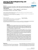
To do BER testing, a PC-controlled BER testbench, as
shown in Figure 6, has been developed which works in con-
junction with the FPGA prototype. In order for the hardware
testbench to be general and flexible, most f unctional mod-
ules such as message generation, FEC encoding, and channel
model are implemented in software. Ethernet communica-
tion is used to download channel data to the hardware FPGA
FEC decoder and upload the decoded results for decoding
performance evaluation. BER results for constraint lengths
with the traceback depth of five times the constraint length
have been obtained and are shown in Figure 7.Themeasured
BER results agree with the expected theoretical results [9].
5. COMPARISONS
Comparisons in terms of area (gates) and speed (through-
put in Mbps) have been obtained from actual FPGA imple-
mentations. These are shown in Ta ble 13. A fixed constraint-
length (K = 7) Viterbi decoder was implemented us-
ing both a state-parallel and an area-efficient architecture
with 5 levels pipelining using 8 ACS units to evaluate the
pipeline scheme. With only 30% of the hardware resources
of a state-parallel implementation, the area-efficient imple-
mentation achieved a throughput of 13.5 Mbps which is
not too far off the theoretical expected rate (5/8 ∗ 32 =
20 Mbps), taking into account the nonuniform delays across
the FPGA. In order to evaluate the reconfiguration overhead,
a fixed constraint length (K = 10) decoder was also im-
plemented and comparisons were made with the reconfig-
urable decoder (K = 7–10). As shown in Table 13 , the con-
figuration overhead is only 1% while the throughputs are
comparable.
The only previous work that is directly comparable to
our work is the one reported in [8] based on a state-parallel
implementation for constraints 3 to 7 only. From Table 13,
for constraint 7, the throughput rate obtained in our case is
inline with the expected ratio of 5/8 compared to the state-
parallel implementation in [8]; of course a significant area
overhead would be incurred by a state-parallel implementa-
tion for constraint lengths from 8 to 10.
Table 13: Throughput rate and Equivalent gate count.
Viterbi decoder
Equivalent gates
Throughput
(Mbps)
State-parallel fixed K = 7 87 836 32
Area-efficient fixed K = 7 26 208 13.5
State-parallel (K = 3–7) [8] 89 407 19.7
Area-efficient fixed K = 10 170 943 1.594
Area-efficient (K = 7–10) 172 618 12.625–1.578
Overall, the results obtained confirmed the design-space
analysis in Section 2, taking into account that the prototypes
are based on FPGA implementations. ASIC implementations
would yield much more improved overall performance.
6. CONCLUSIONS
Broadband access raises new demands for channel coding.
Besides higher decoding speed and decoding capability, re-
configurable decoding performance is highly desired, which
suggests that decoding speed can be traded for decoding ca-
pability to adapt to the dynamic condition of a channel. In
this paper, a novel design and implementation of an online
reconfigurable Viterbi decoder has been proposed based on
an area-efficient ACS architecture in which the constraint
length and tra ceback depth can be dynamically reconfigured.
A design-space exploration to trade off decoding capability,
area, and decoding speed has been performed, from which
the maximum level of pipelining against the number of ACS
units to be used has been determined while maintaining an
in-place path metric updating. A challenging example design
with constraint lengths from 7 to 10 has been presented to-
gether with the new ACS schedule scheme, which provides
5 level ACS pipelining in this case and which can be applied
for any constraint length in a totally uniform way. In gen-
eral, this pipeline scheme can be applied to any area-efficient
architecture with more than 8 time units for each ACS iter-
ation. A modified variable shift path metric normalization
and saturation protection are included in the ACS pipelin-
ing which allows for the path metric memory to be further
reduced by 33% through using lower resolution for the path
metric, compared with the case of modulo path metric nor-
malization. In addition, best-state traceback is used to al-
low significant reduction of survivor memory. The design
has been successfully implemented on Xilinx Virtex FPGA
devices. FPGA implementation results, in terms of decod-
ing speed, resource usage, and BER, have been obtained us-
ing a tailored testbench. These confirmed the functionality
and the expected higher speeds and lower resources. Fur-
thermore, the reconfigurable decoding performance, trading
decoding speed, and area for decoding capability, has been
verified. Further analysis will be carried out to confirm the
expected improvement in power consumption offered by the
proposed architecture.
1326 EURASIP Journal on Applied Sig nal Processing
Ethernet network connection
(cable, router, etc.)
Ethernet coreFEC decoder
FPGA prototyping board
Host PC
Decoding performance evaluation
UDP send/receive
module
Soft/hard decision
quantization
Channel model
FEC
encoder
Message
generator
Figure 6: The block diagram of hardware testbench.
Uncoded
Viterbi7
Viterbi8
Viterbi9
Viterbi10
E
b
/N
0
(dB)
01234567891011
10
−9
10
−8
10
−7
10
−6
10
−5
10
−4
10
−3
10
−2
10
−1
BER
Figure 7: BER results of the configurable Viterbi decoder based on
traceback depth of five t imes constraint length.
REFERENCES
[1] G. D. Forney Jr., “The Viterbi algorithm,” Proceedings of the
IEEE, vol. 61, no. 3, pp. 268–278, 1973.
[2] C. B. Shung, H D. Lin, R. Cypher, P. H. Siegel, and H. K. Tha-
par, “Area-efficient architectures for the Viterbi algorithm. II.
Applications,” IEEE Trans. Communications,vol.41,no.5,pp.
802–807, 1993.
[3] M. B
´
oo,F.Arg
¨
uello, J. D. Bruguera, R. D oallo, and E. L. Za-
pata, “High-performance VLSI architecture for the Viterbi
algorithm,” IEEE Trans. Communications,vol.45,no.2,pp.
168–176, 1997.
[4] K. J. Page and P. M. Chau, “Folding large regular compu-
tational graphs onto smaller processor arrays,” in Advanced
Signal Processing Algorithms, Architectures, and Implementa-
tions VI, vol. 2846 of Proceedings of SPIE, pp. 383–394, Denver,
Colo, USA, August 1996.
[5]P.H.KellyandP.M.Chau, “Aflexibleconstraintlength,
foldable Viterbi decoder,” in Proc. IEEE Global Telecommu-
nications Conference, vol. 1, pp. 631–635, Houston, Tex, USA,
November 1993.
[6] M. Biver, H. Kaeslin, and C. Tommasini, “In-place updating
of path metrics in Viterbi decoders,” IEEE Journal of Solid-
State Circuits, vol. 24, no. 4, pp. 1158–1160, 1989.
[7] J. F. Arrigo, K. J. Page, Y. Wang, and P. M. Chau, “Adaptive
FEC on a reconfigurable processor for wireless multimedia
communications,” in Proc. IEEE Int. Symp. Circuits and Sys-
tems, vol. 4, pp. 417–420, Monterey, Calif, USA, May 1998.
[8] K. Chadha and J. R. Cavallaro, “A reconfigurable Viterbi de-
coder architecture,” in Proc. 35th Asilomar Conference on Sig-
nals, Systems and Computers, vol. 1, pp. 66–71, Pacific Grove,
Calif, USA, November 2001.
[9] G.C.ClarkJr.andJ.B.Cain,Error-Correction Coding for Dig-
ital Communications, Plenum press, NY, USA, 1981.
[10] S Y. Kim, H. Kim, and I C. Park, “Path metric memory
management for minimising interconnections in Viterbi de-
coders,” Elect ronics Letters, vol. 37, no. 14, pp. 925–926, 2001.
[11] A. P. Hekstra, “An alternative to metric rescaling in Viterbi
decoders,” IEEE Trans. Communications, vol. 37, no. 11, pp.
1220–1222, 1989.
[12] C. B. Shung, P. H. Siegel, G. Ungerboeck, and H. K. Thapar,
“VLSI architectures for metric normalization in the Viterbi
algorithm,” in Proc. IEEE International Conference on Com-
munications, vol. 4, pp. 1723–1728, Atlanta, Ga, USA, April
1990.
[13] P. J. Black and T. H. Meng, “A 140-Mb/s, 32-state, Radix-4
Viterbi decoder,” IEEE Journal of solid-state circuits, vol. 27,
no. 12, pp. 1877–1885, 1992.
[14] I. M. Onyszchuk, “Truncation length for Viterbi decoding,”
IEEE Trans. Communications, vol. 39, no. 7, pp. 1023–1026,
1991.
[15] Xilinx Corp., “Virtex 2.5V Field Programmable Gate Arrays
Product Specification,” .
A Novel High-Speed Configurable Viterbi Decoder for Broadband Access 1327
Mohammed Benaissa is currently a Senior
Lecturer in the Electronic and Electrical
Engineering Department at the University
of Sheffield. He is a member of the Elec-
tronic Systems Group. He has been actively
working in the area of VLSI signal process-
ing coding and cryptography for the past
15 years. He has published more than 40
papers in recognized journals and confer-
ences. His recent research concentrate on
investigating configurable approaches to optimum hardware im-
plementation of error control coding and cryptographic techniques
and their incorporation in SOCs.
Yiqun Zhu received the B.S. degree in elec-
trical engineering and M.S. degree in image
processing from Beijing University of Aero-
nautics and Astronautics, China, in 1988
and 1991, respectively. From 1991 to 1998,
he worked in China Aerospace Corporation
as a DSP Engineer. He is currently with the
Electronic Systems Group, Department of
Electronic and Electrical Engineering, the
University of Sheffield, pursuing his Ph.D
degree.