Báo cáo hóa học: " Design and Realization of a New Signal Security System for Multimedia Data Transmission" ppt
Bạn đang xem bản rút gọn của tài liệu. Xem và tải ngay bản đầy đủ của tài liệu tại đây (2.45 MB, 15 trang )
EURASIP Journal on Applied Signal Processing 2003:13, 1291–1305
c
2003 Hindawi Publishing Corporation
Design and Realization of a New Signal Security System
for Multimedia Data Transmission
Hun-Chen Chen
Department of Electronics Engineering, National United University, Miaoli 360, Taiwan
Email:
Jiun-In Guo
Department of Computer Science and Information Engineering, National Chung Cheng University, Chia-Yi 621, Taiwan
Email:
Lin-Chieh Huang
Department of Computer Science and Information Engineering, National Chung Cheng University, Chia-Yi 621, Taiwan
Email:
Jui-Cheng Yen
Department of Electronics Engineering, National United University, Miaoli 360, Taiwan
Email:
Received 22 January 2003 and in revised form 25 August 2003
We propose a new signal security system and its VLSI architecture for real-time multimedia data transmission applications. We
first define two bit-circulation functions for one-dimensional binary array transformation. Then, we exploit a chaotic system in
generating a binary sequence to control the bit-circulation functions defined for performing the successive transformation on the
input data. Each eight 8-bit data elements is regarded as a set and is fed into an 8
× 8 binary matrix being transformed on each
row and each column of the matrix by these two bit-circulation functions such that the signal can be transformed into completely
disordered data. The features of the proposed design include low computational complexity, regular operations suitable for low-
cost VLSI implementation, high data security, and high feasibility for easy integration with commercial multimedia storage and
transmission applications. We have performed Matlab simulation to verify the functional correctness of the proposed system. In
implementing the system, a low-cost VLSI architecture has been designed, verified, and physically realized based on a 0.35 µm
CMOS technology. The implementation results show that the proposed signal security system can achieve 117 Mbytes/s data
throughput rate that is fast enough for real-time data protection in multimedia transmission applications.
Keywords and phrases: signal encryption/decryption, VLSI chip, chaotic system, and fractal dimension.
1. INTRODUCTION
Recently, with the great demand in digital signal transmis-
sion[1, 2] and the big losses from illegal data access, data se-
curity has become a critical and imperative issue in the mul-
timedia data transmission applications. In order to protect
valuable data from undesirable readers or against illegal re-
production and modifications, there have been various data
encryption techniques [3, 4, 5, 6, 7, 8, 9, 10] and the water-
mark embedding schemes [11, 12, 13] on images proposed
in the literature. The data encryption techniques make the
images invisible to undesirable readers and can be applied to
protect the frames in the digital versatile disk (DVD) and the
cable TV, while the watermark-embedded schemes hide the
watermark onto an image to declare their ownership but the
imageisstillvisible.
Among the existing data encryption techniques [3, 4, 5,
6, 7, 8, 9, 10], we can classify their basic design ideas into
three major types: position permutation [5, 6], value trans-
formation [7, 8], and the combination form [9, 10]. The po-
sition permutation algorithms scramble the original data ac-
cording to some predefined schemes. It is simple but usually
has low data security. The value transformation algorithms
transform the data value of the original signal with some
kinds of transformation. It has the potential of low computa-
tional complexity and low hardware cost. Finally, the combi-
nation form performs both position permutation and value
transformation. It has the potential of high data security.
1292 EURASIP Journal on Applied Signal Processing
Pixels
7
j=0
Rotate Y
q,s
j
·
7
i=0
Rotate X
p,r
i
Mapped pixels
Original image
Chaotic binary
sequence
generator
10010 010
10010 010
Chaotic binary
sequence
generator
Decrypted image
7
i=0
Rotate X
¯
p,r
i
·
7
j=0
Rotate Y
¯
q,s
j
Encrypted image
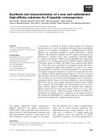
Figure 1: The block diagram of the proposed signal security system applied to a still image encryption/decryption.
In this paper, we propose a new signal security sys-
tem and its VLSI architecture for real-time multimedia data
transmission applications. The proposed encryption algo-
rithm belongs to the category of the combination form
mentioned above. We first define two bit-circulation func-
tions with two par ameters in each function. One is used
to control the shift direction and the other is used to con-
trol the shifted bit-number on the data transformation.
Then, we exploit a chaotic system in generating a binary
sequence to control the bit-circulation functions for per-
forming the successive data transformation on the input
data. Eight 8-bit data elements are regarded as a set and
fed into an 8 × 8 binary matrix. In the successive trans-
formationoneachrowandeachcolumnbyusingthese
two functions, we randomly determine the two parameters
used in the functions according to the generated chaotic
binary sequence such that the signal can b e transformed
into completely disorderly data. In demonstrating the cor-
rect functionality of the proposed signal security system,
we have performed the Matlab simulation on the proposed
scheme. In implementing the proposed system, we present
a low-cost VLSI architecture that has been designed, veri-
fied, and physically realized by using Verilog hardware de-
scription language (HDL), Synopsys logic synthesis tool de-
sign compiler (DC), and Avanti layout tools (Apollo) based
on a 0.35 µm CMOS technology. The implementation results
show that the proposed signal security system can achieve
117 Mbytes/s data throughput rate at the cost of silicon area
of 3.59 mm
2
. This data-processing rate is fast enough for real-
time data protection in multimedia data transmission appli-
cations.
The proposed signal security system is suitable for both
software and hardware implementation depending on the re-
quirement of applications. In the multimedia applications
realized in software or D SP firmware, it i s suggested to re -
alize the proposed system through general-purpose proces-
sors or DSP processors. On the other hand, it is suggested to
use the proposed hardware design in the multimedia appli-
cations realized in hardware like ASICs or SOCs. In this sit-
uation, the system integrators can use the proposed encryp-
tion/decryption design as an independent module or intel-
lectual properties (IP) that can be cooperated with the exist-
ing multimedia ASICs or SOCs to perform the functionality
of real-time data encryption and decryption.
The rest of this paper is organized as follows. In Section 2,
we propose the new signal security system including algo-
rithm derivation and illustration as well as the analysis on
complexity and security. In Section 3, we perform the soft-
ware simulation, randomness measurement, and sensitivit y
analysis of parameters in the proposed system. In Section 4,
we illustrate the hardware design and realization of the pro-
posed system. In Section 5, we evaluate the performance
evaluation of the proposed design and compare it with the
existing designs. Finally, we conclude this paper in Section 6.
2. THE PROPOSED NEW SIGNAL SECURITY SYSTEM
2.1. Notations and definitions
Let g denote a one-dimensional (1D) digital signal of length
N, g(n), 0
≤ n ≤ N − 1, be the one-byte value of the signal g
at n, M an 8 × 8 binary matrix, and g
and M
the encryption
results of g and M, respectively. In the following definitions,
the integer parameters r and s are assumed to be larger than
or equal to 0, but they are less than 8.
Definition 1. The mapping Rotate X
p,r
i
: M → M
is defined
to rotate each bit in the ith row of M,0≤ i ≤ 7, r bits in the
left direction if p equals 1 or r bits in the right direction if p
equals 0.
Definition 2. The mapping Rotate Y
q,s
j
: M → M
is defined
to rotate each bit in the jth column of M,0≤ j ≤ 7, s bits in
the up direction if q equals 1 or s bits in the down direction
if q equals 0.
A New Signal Security System for Multimedia Data Transmission 1293
For example, let
M =
10000111
11001011
10100111
11110001
01100000
11100111
00101000
00111000
, (1)
then,
Rotate X
1,3
3
(M) =
10000111
11001011
10100111
10001111
01100000
11100111
00101000
00111000
,
Rotate Y
1,3
3
(M) =
10010111
11001011
10100111
11100001
01110000
11100111
00101000
00101000
,
Rotate Y
0,2
5
·Rotate X
1,2
2
(M) =
10000011
11001011
10011110
11110001
01100100
11100011
00101000
00111100
.
(2)
In different combinations of p, q, r,ands, the composite
mapping (
7
j=0
Rotate Y
q,s
j
)·(
7
i=0
Rotate X
p,r
i
) possesses the
following three desirable features:
(1) a binary matrix M can b e transformed into quite dif-
ferent matrixes;
(2) different matrixes can be transformed into the same
matrix;
(3) given a transformation pair of M and M
, the combi-
nation of p, q, r,ands resulting in the transformation
pair may be nonunique.
Since M is an 8
× 8 matrix, the result of circulating its
row or column k bits is equal to the result of circulating it
(kmod8) bits in the same direction. This is why r and s are
assumed to be in the ranges of 0 ≤ r ≤ 7and0≤ s ≤ 7.
2.2. The new signal security system
Based on the notations and definitions, the encryption
procedure denoted as the two-dimensional (2D) circula-
tion encryption algorithm (TDCEA) on g is proposed in
Algorithm 1.
Each eight 8-bit data elements are regarded as a process-
ing group and fed into the 8 × 8 binary matrix M.Each
row of M is transformed by Rotate X
p,r
i
, and then each col-
umn of the resulting matrix is transformed by Rotate Y
q,s
j
.In
each row or column transformation, the mapping parame-
ters p, r, q,ands are randomly determined by the chaotic
binary sequence in (3), (4), (6), and (7). The row transfor-
mation belongs to the type of value transformation and the
column transformation makes the position permutation in
each bit-plane. Hence, the TDCEA belongs to the type of
combination-form category in the existing data encryption
schemes.
The decryption procedure is very similar to Algorithm 1
except for the following two modifications.
(1) The j-loop including the assignment of q and s and the
mapping Rotate Y
q,s
j
is changed to be ahead of the i-
loop including the assignment of p and r and the map-
ping Rotate X
p,r
i
.
(2) The parameter q in Rotate Y
q,s
j
changes to its com-
plement INV(q) and the parameter p in Rotate X
p,r
i
changes to its complement INV(p), where INV(x)de-
notes the logically inverting operation on the vari-
able x, that is, the mapping function applied to M
in
the decryption subsystem becomes (
7
i=0
Rotate X
p,r
i
)·
(
7
j=0
Rotate Y
q,s
j
).
Combining the encryption subsystem and decryption
subsystem, the block diagram of the proposed signal secu-
rity system is shown in Figure 1. By extracting 17 bits from
each evolution state of the logistic map, we gener ate a binary
sequence. The reason why we adopt 17 bits depends on the
amount of control signals needed in each cycle when apply-
ing the proposed TDCEA.
Then, the sequence is used to control the parameters in
(
7
j=0
Rotate Y
q,s
j
) · (
7
i=0
Rotate X
p,r
i
) according to (3), (4),
(6), and (7)inAlgorithm 1. That is, the rotation direction
and the shifted bit-number in the mapping are randomly
controlled by the sequence. Finally, each eight pixels are suc-
cessively mapped and the completely chaotic results can be
obtained. In the decryption phase, according to the same
µ and x(0), that is, the same chaotic binary sequence, the
original image can be correctly reconstructed by applying
(
7
i=0
Rotate X
p,r
i
) · (
7
j=0
Rotate Y
q,s
j
) to the encrypted im-
age. The variables µ and x(0) used in the proposed algorithm
can be protected and t ransmitted from transmitters to re-
ceivers using the method illustrated in Section 2.3.
2.3. Generation, protection, and transmission
of the parameters α, β, µ, and x(0)
In the proposed design, we need four parameters α, β, µ,and
x(0) in generating the chaotic bit-stream from the 1D logistic
1294 EURASIP Journal on Applied Signal Processing
Step 1: Determine the parameters N, α,andβ, where 0 <α+ β<8, α ∈ N,and
β ∈ (N ∪{0}), where N denotes the set of positive integers.
Step 2: Determine the parameter µ and the initial point x(0) of the 1D logistic map
f
µ
(x) = µx(1 − x). Evolve successive states from the 1D logistic map [14, 15]by
x(n +1)= µx(n)(1 − x(n)), and the preceding 17 bits below the decimal point
of the binary representation of x(n), n = 1, 2, ,are extracted to constitute the
chaotic binary sequence b(0),b(1),b(2), ,and so forth.
Step 3: For k = 0to(N/8 − 1) Do
For x = 0to7Do
Let g(8k + x) =
7
y=0
d
y
× 2
y
;
For y
= 0to7
M(x, y) = d
y
;
End
End
For i = 0to7Do
p
= b(17k + i), (3)
r = α + β × b(17k + i +1), (4)
M = Rotate X
p,r
i
(M); (5)
End
For j = 0to7Do
q = b(17k +8+ j), (6)
s = α + β × b(17k +9+ j), (7)
M = Rotate Y
q,s
j
(M); (8)
End
For x = 0to7Do
g
(8k + x) =
7
y=0
M(x, y) × 2
y
;(9)
End
End
Step 4: The encryption result g
is obtained and the algorithm is terminated.
Algorithm 1: The two-dimensional circulation encryption algorithm (TDCEA).
map. The four parameters could be viewed as the keys to the
proposed signal security system. Among them, the parame-
ters α and β can be fixed in both the transmitter and receiver
according to the constraint shown in Step 1 of the proposed
TDCEA. In providing higher security of the proposed TD-
CEA, we can try to vary the parameters of µ and x(0) during
the transmission of multimedia data frequently. Let µ
b
and
X
b
denote the built-in keys of µ and x(0), respectively, in the
proposed signal security system. Let µ
enc,0
and X
enc,0
denote
the initial encrypting keys of µ and x(0), respectively, dur-
ing the transmission from the transmitter to the receiver. The
way of generating, protecting, and t ransmitting the parame-
ters of µ and x(0) is shown in the following procedures.
(1) We first select the initial values of µ
0
and x(0)
0
follow-
ing the constraints of 3 <µ
0
< 4and0<x(0)
0
< 1.
(2) Then, we encrypt the initial µ
0
and x(0)
0
by the follow-
ing way :
X
enc,0
= x(0)
0
⊕ X
b
,
µ
enc,0
= µ
0
⊕ µ
b
.
(10)
(3) Transmitting the encrypted µ
enc
and X
enc
from the
transmitter to the receiver for reproducing the initial
µ
0
and x(0)
0
by the following way:
x(0)
0
= X
enc,0
⊕ X
b
,
µ
0
= µ
enc,0
⊕ µ
b
.
(11)
(4) In the pth updating of the parameters µ and x(0), that
is, µ
p
and x(0)
p
,wecanusethevaluesofµ
p−1
and
x(0)
p−1
in the (p − 1)th updating to replace the roles
of the built-in parameters of µ
b
and X
b
. Then, we can
use the way specified in (10)and(11) in protecting the
successive updated parameters of µ and x(0) as follows:
X
enc,p
= x(0)
p
⊕ x(0)
p−1
,
µ
enc,p
= µ
p
⊕ µ
p−1
,
x(0)
p
= X
enc,p
⊕ x(0)
p−1
,
µ
p
= µ
enc,p
⊕ µ
p−1
.
(12)
(5) The updating period of the par a meters of µ and x(0)
could be based on the basic unit of video frame or au-
dio fr ame in representing the multimedia data.
A New Signal Security System for Multimedia Data Transmission 1295
Table 1: The complexity of the proposed TDCEA on a signal of length N.
Operation Multiplication Addition/subtraction Condition test or
Step 2 2N/8N/8 00
Equation (3)ofStep3 NN 00
Equation (4)ofStep3 N 2NN0
Equation (5)ofStep3 0 0 0 N
Equation (6)ofStep3 NN 00
Equation (7)ofStep3 N 2NN0
Equation (8)ofStep3 0 0 0 N
Total 4N +2N/8 6N + N/8 2N 2N
2.4. Chaos via 1D logistic map
A simple and well-studied example of a 1D map [14] that
exhibits complicated behavior is the logistic map from the
interval [0, 1] into [0, 1], parameterized by µ:
g
µ
(x) = µx(1 − x), (13)
where 0 ≤ µ ≤ 4. This map constitutes a discrete-time dy-
namical system in the sense that the map g
µ
:[0, 1] → [0, 1]
generates a semigroup through the operation of composi-
tion of functions. The state evolution is described by x
n+1
=
g
µ
(x
n
). We denote
g
(n)
≡ g ◦ g ◦···◦g (n times). (14)
For all x ∈ [0, 1],a“discrete-time”trajectory{x
i
}
∞
i=0
,where
x
i
= g
(i)
(x), can be generated. The set of points {x
0
,x
1
, }⊂
[0, 1] is called the (forward) orbit of x. A periodic point of g
is a point x ∈ [0, 1] such that x = g
(n)
(x) for some positive
integer n. The least p ositive integer n is called the period of
x. A periodic point of period 1 is called a fixed point. For
differentiable g, a periodic point x with period n is stable if
n
i=1
g
x
i
< 1, (15)
and unstable if
n
i=1
g
x
i
> 1, (16)
where x
i
= g
(i)
(x).
In the logistic map, as µ is varied from 0 to 4, a period-
doubling bifurcation occurs. In the region µ ∈ [0, 3], the
map g
µ
possesses one stable fixed point. As µ is increased past
3, the stable fixed point becomes unstable and two new sta-
ble periodic points of period 2 are created. As µ is further
increased, these stable p eriodic points in turn become unsta-
ble and each spawns two new stable periodic points of period
4. Thus the period of the stable periodic points is doubled at
each bifurcation point. Each period-doubling episode occurs
in a shorter “parameter” interval, decreasing at a geometric
rate each time. Moreover, at a finite µ, the period-doubling
Bifurcation parameter µ
2.53 3.54
x
n
0
0.1
0.2
0.3
0.4
0.5
0.6
0.7
0.8
0.9
1
Figure 2: Bifurcation diagram of the logistic map g
µ
(x) = µx(1−x).
episode converges to an infinite number of period doublings
at which point chaos is observed. This is depicted in the bi-
furcation diagram in Figure 2.
2.5. Analysis of computational complexity
If the TD CEA is simulated by using C language, just the
basic bitwise operators “”and“” can accomplish the
mappings Rotate X
p,r
i
and Rotate Y
q,s
j
.InStep2,itrequires
one subtraction and two multiplications to evolve a state
from the 1D logistic map, and the total evolution number is
N/8,wherey denotes the largest integer that is smaller
than or equal to y.In(4)and(7), since b(n) is either 1
or 0, the equations can be performed by one condition test
and two additions instead. The computational complexity
of the proposed TDCEA on a signal of length N is listed in
Tabl e 1.FromTable 1, the numbers of multiplications, addi-
tions/subtract ions, condition tests, and circular shiftings are
4N +2N/8,6N + N/8,2N,and2N, respectively. Hence,
the computational complexity of the TDCEA is proportional
to O(N).
2.6. Analysis of security problem
It is of interests to know if the TDCEA is easily decrypted or
not. This security problem is analyzed in the following.
1296 EURASIP Journal on Applied Signal Processing
Proposition 1. For an unknown set of µ and x(0) of the logistic
map, the number of possible encry ption results is 2
17N/8
if the
TDCEA is applied to a signal of length N.
Proof. Since it requires 17N/8 bits to encr ypt a signal of
length N, the number of possible encryption results is
2
17N/8
.
For example, consider an image of size 256 × 256 pix-
els. In this case, N equals 65536. All the possibilities are
2
139264
(
∼
=
10
41918
). Since the chaotic binary sequence is un-
predictable [16], it is very difficult to decrypt correctly an
encrypted signal by making an exhaustive search without
knowing µ and x(0). Moreover, small fluctuation in µ and
x(0) results in quite different chaotic binary sequence be-
cause the trajectory of the chaotic system is very sensitive
to initial condition [16]. By way of collecting some original
signals and their encryption results or collecting some spec-
ified signals and their corresponding encryption results, it is
impossible for the cryptanalysts to decrypt correctly an en-
crypted image without knowing µ and x(0) because the rota-
tion direction and the shifted bit-number in each row or col-
umn transformation is randomly determined by the chaotic
binary sequence. Hence, the new scheme can resist the cho-
sen ciphertext attack and the known plaintext attack [17].
3. SIMULATION RESULTS
3.1. Software simulation and the calculation
of fractal dimension
In the simulation, ten images of size 256 × 256 are used. As
representatives, only the images of “cman,” “aero,” and “pep-
per” are shown in Figures 3a, 3d,and3g,respectively.The
most direct method to decide the disorderly degree of the en-
crypted image is by the sense of sight. On the other hand, the
fractal dimension [18, 19] can provide the quantitative mea-
sure on the randomness of the encrypted images. General
images typically have a degree of randomness associated with
both the natural random nature of the underlying structure
and the random noise superimposed on the image. An image
f of size L × P pixels is regarded as a surface with z = f (x, y)
in R
3
. To measure how rough the encrypted image surface is,
its fractal dimension D is calculated according to the method
in [19].
Let ndi(k) be the average of absolute intensity difference
of all pixel pairs with distance values whose integer parts are
k. The value of ndi(k)iscomputedby
ndi(k)
=
L−1
x1=0
P−1
y1=0
L−1
x2=0
P−1
y2=0
f (x2,y2) − f (x1,y1)
npn(k)
,
(17)
where npn(k) is the total number of pixel pairs with distance
∆r such that k
≤ ∆r<k+1,andx1, y1, x2, and y2must
satisfy
k ≤
(x2 − x1)
2
+(y2 − y1)
2
<k+1. (18)
Plot all pairs (log(k), log(ndi(k))), and then use a least-
squares linear regression to estimate the slope H of the resul-
tant curve. The fractal dimension D = 3−H can be obtained.
In the simulation, the maximal distance k between two pixels
in (17) is set to 60.
In order to apply the TDCEA, the parameters α and β
must be determined according to Step 1. Basically, the selec-
tion of α and β should follow the empirical law. According to
the experimental experience, general combinations of α and
β can always result in very disorderly results. In the simula-
tion, α = 2andβ = 2 are adopted in Step 1. In the logistic
map, x(0) = 0.75 and µ = 3.9 are set in Step 2. The encrypted
results of the three representative images by the TDCEA are
shown in Figures 3b, 3e,and3h. Moreover, the fractal dimen-
sions of the original images and their encryption results are
calculated and listed in Table 2.
According to Figure 3, the encryption results of the TD-
CEA a re of complete disorder and cannot be distinguished
from the original ones. Moreover, from the quantitative mea-
sure results shown in Ta ble 2, the fractal dimensions of the
encrypted images range from 2.9974 to 2.9830. Since the
maximal fractal dimension for a 2D surface is 3.00, the en-
cryption results of the TDCEA are completely disordered.
Figures 3c, 3f,and3i, respectively, show the decrypted images
of “cman,” “aero,” and “pepper.” Since the proposed TDCEA
is not losable, we can find that there would be no encryp-
tion/decryption errors in using the proposed TDCEA.
3.2. Analysis of parameter sensitivity
In order to demonstrate that the encryption results of the
TDCEA are very sensitive to µ and x(0), tiny fluctuation in
the two parameters is considered. To compare the encryp-
tion results with smal l parameter fluctuation, the root mean
square difference (RMSD) is computed. Let f
µ
1
,x
1
(0)
be the en-
cryption result of the image f under µ
1
and x
1
(0) and let
f
µ
2
,x
2
(0)
be the one under µ
2
and x
2
(0); the RMSD between
f
µ
1
,x
1
(0)
and f
µ
2
,x
2
(0)
is defined as
RMSD ≡
1
L × P
L−1
i=0
P−1
j=0
f
µ
1
,x
1
(0)
(i, j) − f
µ
2
,x
2
(0)
(i, j)
2
1/2
,
(19)
where f is an image of size L × P pixels. Firstly, x(0) is fixed
to be 0.75 and tiny fluctuation of 10
−5
in µ is considered.
The RMSD comparison result of “Lena” is listed in Table 3.
Secondly, µ is fixed to be 3.9 and tiny fluctuation of 10
−5
in
x(0) is considered. The RMSD between each fluctuation is
listed in Ta ble 4 . From Tables 3 and 4, the RMSDs range from
91.1739 to 92.6910. The average gray-level difference of each
pixel between the two encryption results with tiny fluctua-
tion in µ or x(0) is about 92. It implies that the two results
are extraordinarily different. Hence, the encryption result of
the TDCEA is very sensitive to the fluctuation in µ and x(0).
4. ARCHITECTURE DESIGN AND REALIZAT ION
Figure 4a shows the architecture of the proposed new signal
security system. It includes one signal encryption unit (SEU),
A New Signal Security System for Multimedia Data Transmission 1297
(a) (b) (c)
(d) (e) (f)
(g) (h) (i)
Figure 3: (a) Original “Cman,” (b) encrypted “Cman,” (c) decry pted “Cman,” (d) original “Aero,” (e) encrypted “Aero,” (f) decrypted “Aero,”
(g) original “Pepper,” (h) encrypted “Pepper,” and (i) decrypted “Pepper.”
Table 2: The fractal dimensions of the original and encrypted images.
Cman Einstein Mill Lena Aero Baboon Pepper Boat Boys Karen
Original Image 2.5671 2.6702 2.8087 2.5993 2.7427 2.7178 2.6407 2.7885 2.4878 2.5932
Encrypted Image 2.9830 2.9937 2.9957 2.9924 2.9957 2.9974 2.9947 2.9894 2.9906 2.9901
Table 3: The RMSD between the encryption results with x(0) = 0.75 and tiny fluctuation of 10
−5
in µ.
3.9000 3.90001 3.90002 3.90003 3.90004 3.90005 3.90006 3.90007 3.90008
µ vs. vs. vs. vs. vs. vs. vs. vs. vs.
3.90001 3.90002 3.90003 3.90004 3.90005 3.90006 3.90007 3.90008 3.90009
RMSD 91.7405 91.7855 92.0908 91.7223 92.4095 92.0035 92.0625 92.1774 91.9920
1298 EURASIP Journal on Applied Signal Processing
Table 4: The RMSD between the encryption results with µ = 3.9 and tiny fluctuation of 10
−5
in x(0).
0.75000 0.75001 0.75002 0.75003 0.75004 0.75005 0.75006 0.75007 0.75008
x(0) vs. vs. vs. vs. vs. vs. vs. vs. vs.
0.75001 0.75002 0.75003 0.75004 0.75005 0.75006 0.75007 0.75008 0.75009
RMSD 92.0361 92.0357 92.2701 92.5990 92.6580 92.1739 91.8318 92.4014 92.6910
one signal decryption unit (SDU), and two chaotic binary se-
quence generators (CBSGs). From the proposed algorithm,
we find that the SDU operation is very similar to the SEU op-
eration except that the directions of the left/right shifting on
the row data and the up/down shifting on the column data
are opposite. So, with opposite control signals in the shift-
ing directions, the same SEU architecture can be used in the
SDU. Thus, we design an encryption/decryption core for the
proposed system as shown in Figure 4b. Figure 5 shows the
architecture of the SEU/SDU in the encryption/decryption
core. In the SEU/SDU desig n, we adopt the 2D array of
processing elements (PEs) as shown in Figure 6 to perform
the signal encryption/decrypt ion operation on eight pixels
simultaneously in bit level. That is, each PE has been de-
signed to perform the following functions including loading,
left/right shifting, and up/down shifting under the control of
the parameters p, q, r,ands, derived from the chaotic binary
sequence b(·) that is obtained from the CBSG as shown in
Figure 7. As shown in Figure 6, the PE in the proposed design
is composed of the data multiplexing circuit and D-type flip-
flop (DFF). Using data multiplexing circuit is to achieve the
loading/outputting, left/right (L/R) rotation, and up/down
(U/D) rotation using the same DFF. Since the shifting oper-
ations with variant numbers of bits are needed in the pro-
posed design, we use DFF with configurable input sources to
achieve this goal in multiple clock cycles instead of disabling
the clock signal to the DFF. For each left/r ight shifting on the
row data, it takes 8 cycles to finish the operations in the worst
case. Similarly, it also takes 8 cycles to finish the up/down
shifting operations for the column data in the worst case. In-
cluding the initial 8 cycles needed to feed the input data into
the 2D array of PEs, it totally takes 24 cycles to finish the sig-
nal encryption operation for each 8 input pixels. For balanc-
ing the I/O data processing rates, we use three data security
block (DSB) modules in the SEU/SDU design such that we
can achieve the data throughput rate of 1 pixel/cycle. This
arrangement results in the pipeline operations on the DSB
modules in the SEU/SDU.
Tabl e 5 shows the scheduling of the DSB operations in
the proposed design under pipelining and nonpipelining or-
ganization. In the pipelining organization ( as the proposed
design in Figure 5), we see that three DSBs perform the op-
erations of loading/outputting, L/R rotation, and U/D ro-
tation repeatedly so that the data throughput rate is equal
to 1 Byte/cycle. The maximum throughput rate amounts to
117 Mbyte/s with the cycle time of 8.55 nanoseconds. On the
other hand, if we only use one DSB instead of three in the
SEU/SDU design, it is said to be in the nonpipelining orga-
nization. In this case, we can trade off the hardware cost and
the data throughput rate by removing two DSBs and lower-
ing down the data throughput rate to 39 Mbyte/s in maxi-
mum. It leaves a freedom for users to select the pipelining or
nonpipelining organizations when using the proposed design
in different multimedia applications.
Besides, as we show in Figure 6, the control of the PEs is
accomplished through the ctrl[4 : 0] signal. The ctrl[4 : 0]
signal is composed of five control lines used in the PEs. For
illustrating how to control the operations of PEs through
ctrl[4 : 0], we also show an example of assigning ctrl[4 : 0]
in Figure 6 when the PEs are operated in different o peration
modes like loading/outputting, L/R rotation, and U/D ro-
tation. In case that the data is loaded into the 2D array in
DSB, it is loaded through the ports, Ext in and out, directly
without using the four bidirectional data ports Li, Ri, Ui, and
Di. When the L/R rotation and U/D rotation operations are
performed, the data is shifted through the four bidirectional
ports under the control of ctrl[4 : 0] as illustrated in Figure 6.
Figure 7 shows the architecture of the CBSG for the 1D
logistic map. The parameters of x(0) and µ are downloaded
into the registers resided in the CBSG sequentially. Then, the
CBSG performs the state evolution according to the behav-
ior of the adopted 1D logistic map shown in (10). In or-
der to minimize the hardware cost, only one multiplier is
used for the state evolution. Each new state x(n +1)iscom-
puted serially in two cycles according to the control signal
shown in Table 6.Atoddcycles,µ and x(n) are multiplied.
At even cycles, µx(n)and(1− x(n)) are multiplied. That is,
the CBSG generates 17 bits in the chaotic binary sequence ev-
ery two cycles. Since the computation time for generating the
chaotic binary sequence is much longer than that needed in
the PEs, we use the design concept of multiple clock sources
in the proposed design. T hat means we use a slower clock
source in the CBSG design by dividing the original clock
source by a factor. The value of the dividing factor should
be determined by considering the consumption time of the
PEs, multiplier in the CBSG, as well as the data consump-
tion rate of the chaotic binary sequence. Besides, we also have
to consider the complexity of the clock-dividing circuits and
the synchronization between the two clocks. Ta ble 7 shows
the timing information and the control data consumption
rate of the SEU/SDU and CBSGs in the proposed design.
According to the results shown in Table 7, we find that the
minimum consumption time p er cycle in the SEU/SDU is
about 8.55 nanoseconds and that the SEU/SDU consumes
17 bits of the control signals within 68.4 nanoseconds (in
8 cycles). Besides, we find that the minimum consumption
A New Signal Security System for Multimedia Data Transmission 1299
Signal g(n)
8
Signal
encryption
unit (SEU)
α
β
g
(n)
Signal
decryption
unit (SDU)
Decrypted
signal g
(n)
8
Chaotic binary
sequence
generator
(CBSG)
÷
CLK
x(0)
µ
÷
Chaotic binary
sequence
generator
(CBSG)
Encryption core Decryption core
(a) Architecture.
g(n)
rotate a
rotate b
rotate ctrl
de flag
reset
clk
CBSG in
CBSG ctrl
8
3
3
÷
17
2
CBSG
17
SEU
SDU
8
g
(n)
(b) Encryption/decryption core.
Figure 4: The architecture of the proposed signal securit y system.
per cycle in the CBSG is about 14.5 nanoseconds and that
the CBSG generates 17 bits of the control sig nals within 29
nanoseconds (in 2 cycles for saving the hardware cost as
we describe in Figure 7). Since the CBSG only uses 2 cy-
cles to generate 17 bits of the control signals that are con-
sumed by the SEU/SDU in 8 cycles, the operating frequency
of CBSG could be only 1/4 of that used in the SEU/SDU.
Therefore, we select the dividing factor to be 4 in dividing
the clock of SEU/SDU before sending it to the CBSG. In
this case, even if the operating frequency of the SEU/SDU
achieves the maximum allowable 117 MHz, the operating
frequency of that used in the CBSG should be 29.25 MHz
in maximum. Using this operating frequency in the CBSG
will not have timing problems since we have 34.2nanosec-
onds that is larger than the minimum time interval (i.e., 29
nanoseconds) to generate the 17 bits of the control signals by
CBSG.
Figure 8 shows the clock-dividing circuit and the as-
sociated gate-level simulation results to illustrate the phe-
nomenon of clock skew. From the gate-level simulation
shown in Figure 8, we fi nd that the clock skew period be-
tween the two clock sources used in SEU/SDU and CBSGs is
about 1.14 nanosecond. Similar results are also found by ex-
amining the post-layout simulation. We have considered the
problem of clock skew in deciding the clock dividing factor.
Therefore, we can conclude that the clock skew problem of
the two clock sources used in SEU/SDU and CBSGs does not
have synchronization problems influencing the timing per-
formance of the proposed design.
To verify the architecture of the proposed signal secu-
rity system, we perform register transfer level (RTL) mod-
eling of the proposed architecture by using Verilog HDL.
In addition, we have performed the logic synthesis and the
critical path analysis on the proposed architecture by us-
ing Synopsys logic synthesis tool DC based on a 0.35 µm
CMOS technology. Finally, we have implemented the pro-
posed signal security system created by Avanti layout tools
(Apollo). Table 8 shows the physical implementation results
of the proposed signal security system. We found that the
critical path of the proposed design is about 8.55 nanosec-
onds that achieves 117 MHz data throughput rate. This pro-
cessing speed can support up to 117 Mbytes/s in data en-
crypting and decrypting, which is fast enough to meet the
real-time processing requirements of many digital image and
1300 EURASIP Journal on Applied Signal Processing
g(n)
DFC1= 00, 00, 00, 00, 00, 00, 00, 00, 01, 01, 01, 01, 01, 01, 01, 01, 10, 10, 10, 10, 10, 10, 10, 10,
DFC2= 00, 00, 00, 00, 00, 00, 00, 00, 01, 01, 01, 01, 01, 01, 01, 01, 10, 10, 10, 10, 10, 10, 10, 10,
repeat
DFC1
DEMUX
10 01 00
8
Data security block 1 (DSB1)
11111 111
11111 111
PE PE PE PE PE PE PE PE
PE PE PE PE PE PE PE PE
PE PE PE PE PE PE PE PE
PE PE PE PE PE PE PE PE
PE PE PE PE PE PE PE PE
PE PE PE PE PE PE PE PE
PE PE PE PE PE PE PE PE
PE PE PE PE PE PE PE PE
17
17
17
8
8
8
8
8
CB[16 : 0]
g
(n)
DEMUX
10 01 00
DSB2
DSB3
DFC2
Figure 5: The architecture of the SEU/SDU in the proposed signal security system design.
video applications. Figure 9 shows the layout view according
to a 0.35 µm CMOS technology. The chip area of the pro-
posed system is 3584443.28 µm
2
.
5. PERFORMANCE EVALUATION AND COMPARISONS
This section provides the performance evaluation of the pro-
posed design with other existing designs [20, 21, 22, 23, 24,
25]. In order to eliminate the factor of different fabrication
technologies, we define an index of normalized area (denoted
by NArea), which is the silicon area normalized to a 0.35 µm
technology as shown as follows:
NArea =
Area
(Technology/0.35)
2
. (20)
Besides, we also define an index of data rate per area (DRPA),
that is, Data rate/NArea, as shown in ( 21 ), to reflect the ef-
ficiency of the hardware design for data encrypter and de-
crypter. It is shown as follows:
DRPA =
Data − rate
NArea
Mbps/mm
2
. (21)
A New Signal Security System for Multimedia Data Transmission 1301
ctrl vo Ui out
Li
ctrl hi
ctrl vi Di Ext in
ctrl ho
Ri
PE
p
Li
Ri
Ui
Di
q
rc
M
U
X
opmode
M
U
X
0
1
0
1
1
0
1
M
U
X
D
Q
DFF
clk
rst
out
Ext in
Q value
M
U
X
M
U
X
load
1
0
0
ctrl hi
5
ctrl ho
ctrl vi
5
ctrl vo
bit 4 bit 3 bit 2 bit 1 bit 0
qp
rc
load
opmode
Bit field definition of ctrl handctrl v
CB[16 : 0]
Control code
generator
(using ROM)
ctrl[4 : 0]
ctrl[4 : 0] code assignment
Operations ctrl[4 : 0]
Loading/outputing 00010
L/R rotation
0p101 in the first r cycles
0p100 in the remaining cycles
U/D rotation
q0001 in the first s cycles
q0000 in the remaining cycles
Figure 6: The architecture of the PEs used in the DSB in the proposed SEU/SDU.
Based on the above two indices, we have summarized the
comparison results of the proposed design with the exist-
ing ones [20, 21, 22, 23, 24, 25]inTable 9.FromTable 9,
we find that the proposed design is better than the design
in [20] in providing higher data processing rate at lower
hardware cost weighted using gate count based on a 0.35 µm
CMOS technology. Also, the proposed design achieves higher
data-processing rate at lower hardware cost in gate count as
compared with the design in [25]. As for the comparison
to the other popular data encryption/decryption approaches
[21, 22, 23, 24, 25], we use the normalized index of DRPA
defined in (21) in the evaluation of the efficiency in these
approaches. We find that the proposed design is better than
the existing desig ns in [21, 22, 23, 24] in possessing higher
DRPA. That means that the proposed design can provide
higher efficiency considering the data processing rate and re-
quired hardware cost. Thoug h the above comparison cannot
provide the absolute comparison in every aspect (including
1302 EURASIP Journal on Applied Signal Processing
x(n − 1) at even cycles
x(n)atevencycles
µx(n−1) at odd cycles
x(0)
17
17
17
17
0
1
1
0
C2
C2
M
U
X
M
U
X
17
1
S
U
B
17
17
0
1
17
C1
M
U
X
MUL
17
D
E
M
U
X
0
17 17
CB[16 : 0]
1
17
µ
17
17
1
0
M
U
X
C1
17
D
D
C1
Figure 7: The architecture of the CBSG used in the proposed signal secur ity system.
Table 5: The scheduling of DSB operations in the proposed design, where Dn denotes the nth set (with 8 bytes in a set) of data.
(a) Pipelining organization (using three DSBs as proposed in Figure 5).
DSB modules
Cycle DSB1 DSB2 DSB3 Data output
0 ∼ 7 Load D1 — — —
8 ∼ 15 L/R rotation on D1 Load D2 — —
16 ∼ 23 U/D rotation on D1 L/R rotation on D2 Load D3 —
24 ∼ 31 Load D4/output D1 U/D rotation on D2 L/R rotation on D3 D1
32 ∼ 39 L/R rotation on D4 Load D5/output D2 U/D rotation on D3 D2
40 ∼ 47 U/D rotation on D4 L/R rotation on D5 Load D6/output D3 D3
48 ∼ 55 Load D7/output D4 U/D rotation on D5 L/R rotation on D6 D4
56 ∼ 63 L/R rotation on D7 Load D8/output D5 U/D rotation on D6 D5
64 ∼ 71 U/D rotation on D7 L/R rotation on D8 Load D9/output D6 D6
72 ∼ 79 — U/D rotation on D8 L/R rotation on D9 D7
80 ∼ 87 — — U/D rotation on D9 D8
(b) Nonpipelining organization (using only one DSB).
DSB modules
Cycle DSB Data output
0 ∼ 7 Load D1 —
8 ∼ 15 L/R rotation on D1 —
16 ∼ 23 U/DrotationonD1 —
24 ∼ 31 Lo ad D2/output D1 D1
32 ∼ 39 L/R rotation on D2 —
40 ∼ 47 U/DrotationonD2 —
48 ∼ 55 Lo ad D3/output D2 D2
56 ∼ 63 L/R rotation on D3 —
64 ∼ 71 U/DrotationonD3 —
72 ∼ 79 Lo ad D4/output D3 D3
80 ∼ 87 ——
A New Signal Security System for Multimedia Data Transmission 1303
Table 6: The assignments of the control sig nals C1 and C2 in the CBSG.
Time 12345678910···
C1 1010101010···
C2 1100000000···
Output — CB[16 : 0] — CB[16 : 0] — CB[16 : 0] — CB[16 : 0] — CB[16 : 0] ···
Table 7: The timing information and the consumption rate of the control signals in the SEU/SDU and CBSGs.
Minimum consumption time
with clock skew per cycle (ns)
Consumption/generation
rate in control signals
Clock dividing factor
(F
SEU/SDU
/F
CBSG
)
Maximum clock
frequency (MHz)
Meeting critical
path constraint
SEU/SDU 8.55 17 bits/68.4 ns (in 8 cycles) 4 (= 8 cycles/2 cycles) 117 Yes
CBSGs 14.5(= 13.36 + 1.14) 17 bits/29 ns (in 2 cycles) 4 (= 8 cycles/2cycles) 29.25 (= 117/4) Yes
old clk
rst
new clk
(a) Clock dividing circuit optimized by Synopsys design
compiler.
(b) Gate-level simulation regarding clock skew (clock skew is
about 1.14 nanosecond).
Figure 8: Clock div iding circuit and the associated gate-level
simulation results regarding clocks (CLK
SEU/SDU
= old clk and
CLK
CBSG
= new clk) in the proposed design.
the efficiency as well as other factors like security and so on)
between the proposed design and others, it can reflect the
efficiency of the proposed design under the situation that
the security of the proposed design and the existing ones
[20, 21, 22, 23, 24, 25] is good enough for the applications.
When the proposed TDCEA design is applied to the data
protection in the multimedia data transmission, we may face
a problem that the encrypted data is lost or corrupted by
noise. In the proposed design, it uses 8-byte data as a unit
Table 8: The details of the physical implementation on the pro-
posed signal security system.
Item Result
Technology COMPASS 0.35 µmCMOS
Power supply 3.3V
Area in gate count 12721 gates
Critical path delay 8.55 ns
Chip size 3584443.28 µm
2
∼ 3.59 mm
2
Power consumption 20 mW@50 MHz
in the encrypting or decrypting processes. Different units of
8-byte data are encrypted or decrypted independently except
for using the neighboring bit-stream data as the control sig-
nals. If there is any loss or data corruption in the encrypted
data when transmitted in the network, it would cause data
errors in the around 8-byte data that contains the lost one.
And the error will not propagate if we also flush the associ-
ated control signals with the corrupted data. Since the pro-
posed design is targeted at the applications of multimedia
data transmission, the errors caused by the interference f rom
network could be recovered by exploiting the well-developed
multimedia error concealment approaches proposed in the
literature.
6. CONCLUSION
In this paper, we have proposed a new signal security system
with its VLSI architecture designed, verified, and physically
realized by using Verilog HDL and Synopsys logic synthe-
sis tool (Design Compiler), and Avanti layout tools (Apollo)
based on a 0.35 µm CMOS technology. The features of the
proposed signal security system include O(N) computational
complexity, high security, and low hardware cost. The simu-
lation results have indicated that (1) the encryption results
are completely chaotic by the sense of sig ht or by the high
fractal dimension, and (2) the encryption results are very
sensitive to the parameter fluctuation. In addition, we have
implemented the proposed design in silicon that possesses
1304 EURASIP Journal on Applied Signal Processing
Figure 9: The layout view of the proposed signal security system implemented using 0.35 µm CMOS technology.
Table 9: Comparison of the proposed design with the existing designs [20, 21, 22, 23, 24, 25].
Design
Technology
(µm)
Area
(mm
2
)
Gate
count
Data rate
(Mbits/s)
Normalized area
(NArea) (mm
2
)
Data rate/NArea
(DRPA) (Mbps/mm
2
)
Encryption
algorithm
Cipher block
length (bit)
Design [20]0.35 — 55345 395 — — FEA-M 64
Design [21]0.7 29 — 251.87.25 34.73 SAFER K-128 64
Design [22]0.35 13.69 51400 600 13.69 43.82 AES 128
Design [23]1.2 107.8 — 177.89.17 19.39 IDEA 64
Design [24]0.811.7 — 355 2.24 158.53 IDEA 64
Design [25]0.25 — 31957 609 — — AES 128
Proposed 0.35 3.59 12721 856 3.59 238.44 TDCEA 64
the data processing rate up to 117 Mbytes/s at the cost of sil-
icon area of 3.59 mm
2
. The comparison results of the pro-
posed design with other existing designs show that the pro-
posed design possesses better performance in terms of the
evaluation index of DRPA, which shows the efficiency of the
proposed design. Finally, it is believed that many real-time
digital signal processing systems can benefit from the inte-
gration with the proposed signal security system for provid-
ing high data security in data storage and transmission.
REFERENCES
[1] S. Moni and R. L. Kashyap, “Image communication over a dis-
tributed multimedia system,” IEEE Journal on Selected Areas
in Communications, vol. 14, no. 7, pp. 1472–1483, 1996.
[2] Y. Yamamoto, F. Inumaru, S. D. Akers, and K. I. Nishimura,
“Transmission perfor mance of 64 Kbps switched digital inter-
national ISDN connections,” IEEE Trans. Communications,
vol. 42, no. 12, pp. 3215–3220, 1994.
[3] W. Diffie and M. E. Hellman, “Privacy and authentication: an
introduction to cryp tography,” Proceedings of the IEEE, vol.
67, no. 3, pp. 397–427, 1979.
[4] M. E. Smid and D. K. Branstad, “The data encryption stan-
dard: past and future,” Proceedings of the IEEE, vol. 76, no. 5,
pp. 550–559, 1988.
[5] J C. Yen and J I. Guo, “An efficient hierarchical chaotic
image encryption algorithm and its VLSI realization,” IEE
Proceedings—Vision, Image and Signal Processing, vol. 147, no.
2, pp. 167–175, 2000.
[6] N. Bourbakis and C. Alexopoulos, “Picture data encryption
using SCAN patterns,” Pattern Recognition,vol.25,no.6,pp.
567–581, 1992.
[7] P. Refregier and B. Javidi, “Optical-image encryption based
on input plane and Fourier plane random encoding,” Optics
Letters, vol. 20, no. 7, pp. 767–769, 1995.
[8] J C. Yen and J I. Guo, “A chaotic neural network for sig-
nal encryption/decryp tion and its VLSI architecture,” in Proc.
10th VLSI Design/CAD Symposium, pp. 319–322, Nan-Tou,
Taiwan, August 1999.
[9] T. J. Chuang and J. C. Lin, “A new multiresolution approach
to still image encryption,” Pattern recognition and Image Anal-
ysis, vol. 9, no. 3, pp. 431–436, 1999.
[10] C. J. Kuo and M. S. Chen, “A new signal encryption technique
and its attack study,” in Proc. IEEE International Carnahan
Conference On Security Technology, pp. 149–153, Taipei, Tai-
wan, October 1991.
A New Signal Security System for Multimedia Data Transmission 1305
[11] C. T. Hsu and J. L. Wu, “Hidden digital watermarks in im-
ages,” IEEE Trans. Image Processing, vol. 8, no. 1, pp. 58–68,
1999.
[12] B. M. Macq and J J. Quisquater, “Cryptology for digital TV
broadcasting,” Proceedings of the IEEE, vol. 83, no. 6, pp. 944–
957, 1995.
[13] Z. Xiong and Y. Q. Zhang, “Multiresolution watermarking for
images and video,” IEEE Trans. Circuits and Systems for Video
Technology, vol. 9, no. 4, pp. 545–550, 1999.
[14] C. W. Wu and N. F. Rulkov, “Studying chaos via 1-D maps—a
tutorial,” IEEE Trans. on Circuits and Systems I: Fundamental
Theory and Applications, vol. 40, no. 10, pp. 707–721, 1993.
[15] H. G. Schuster, Deterministic Chaos: An Introduction,Physik-
Verlag, Weinheim, Germany, 1984.
[16] T. S. Parker and L. O. Chua, “Chaos: a tutorial for engineers,”
Proceedings of the IEEE, vol. 75, no. 8, pp. 982–1008, 1987.
[17] E. Biham, “Cryptanalysis of the chaotic-map cryptosystem
suggested at Eurocrypt ’91,” in Advances in Cryptology—
Eurocrypt ’91: Proc. Workshop on the Theory and Application
of Cryptog raphic Techniques, pp. 532–534, Springer-Verlag,
Berlin, April 1991.
[18] A. E. Jacquin, “Fractal image coding: A review,” Proceedings
of the IEEE, vol. 81, no. 10, pp. 1451–1465, 1993.
[19] C. C. Chen, J. S. Daponte, and M. D. Fox, “Fractal feature
analysis and classification in medical imaging,” IEEE Trans.
on Medical Imaging, vol. 8, no. 2, pp. 133–142, 1989.
[20] X.Yi,C.H.Tan,C.K.Siew,andM.R.Syed,“Fastencryption
for multimedia,” IEEE Transactions on Consumer Electronics,
vol. 47, no. 1, pp. 101–107, 2001.
[21] A. Schubert, V. Meyer, and W. Anheier, “Reusable crypto-
graphic VLSI core based on the SAFER K-128 algorithm with
251.8 Mbit/s throughput,” in Proc. IEEE Workshop on Signal
Processing Systems, pp. 437–446, Cambridge, Mass, USA, Oc-
tober 1998.
[22] Y. Mitsuyama, Z. Andales, T. Onoye, and I. Shirakawa, “VLSI
implementation of high performance burst mode for 128-bit
block ciphers,” in Proc. IEEE Int. Symp. Circuits and Systems,
vol. 2, pp. 344–347, Sydney, Australia, May 2001.
[23] A. Curiger, H. Bonnenberg, R. Zimmermann, N. Felber,
H. Kaeslin, and W. Fichtner, “VINCI: VLSI implementation of
the new secret-key block cipher IDEA,” in Proc. IEEE Custom
Integrated Circuits Conference, pp. 15.5.1–15.5.4, San Diego,
Calif, USA, May 1993.
[24] S. Wolter, H. Matz, A. Schubert, and R. Laur, “On the VLSI
implementation of the internal data encryption algorithm
IDEA,” in Proc. IEEE Int. Symp. Circuits and Systems, vol. 1,
pp. 397–400, Seattle, Wash, USA, 1995.
[25] C C. Lu and S Y. Tseng, “Integrated desig n of AES (Ad-
vanced Encryption Standard) encrypter and decrypter,” in
Proc. IEEE 13th International Conference on Application-
Specific Systems, Architectures, and Processors, pp. 277–285,
San Jose, Calif, USA, July 2002.
Hun-Chen Chen was born in Taipei, Tai-
wan, in 1961. He received the B.S. and
M.S. degrees, all in electronics engineering,
from the National Taiwan Technology Uni-
versity, Taipei, Taiwan, and National Chiao
Tung University, Hsinchu, Taiwan, in 1990
and 1998, respectively. He is currently an
Instructor in the Department of Electron-
ics Engineering, National United University,
Miaoli, Taiwan. His research interests in-
clude neural network application, digital signal processing, and
VLSI architecture design.
Jiun-In Guo was born in Kaohsiung, Tai-
wan, in 1966. He received the B.S. and Ph.D.
degrees in electronics engineering from Na-
tional Chiao Tung University, Hsinchu, Tai-
wan, in 1989 and 1993, respectively. He is
currently a Professor in the Department of
Computer Science and Information Engi-
neering, National Chung-Cheng University,
Chiayi, Taiwan, where he was an Associate
Professor from 2001 to 2003. He was an As-
sociate Professor in the Department of Electronics Engineering,
National Lien-Ho Institute of Technology from 1994 to 2001 and
Director of the same department from 1996 to 1999. His research
interests include image, speech, and digital signal processing, VLSI
architecture design, VLSI implementation, digital IP design, and
SOC design.
Lin-Chieh Huang wasborninKaohsiung,
Taiwan, in 1979. He received the B.S. de-
gree from the Department of Computer
Science and Information Engineering, Na-
tional Chi Nan University, Nan-tou, Tai-
wan, in 2002. He is currently working on
his M.S. degree in the Depart ment of Com-
puter Science and Information Engineering,
National Chung Cheng University. His re-
search interests include video processing al-
gorithm, VLSI architecture design, digital IP design, SOC hardware
design, multimedia ASIC/IP/SOC design, image signal processing,
and computer vision.
J ui-Cheng Yen was born in Tainan, Taiwan,
in 1963. He received the B.S. and Ph.D.
degrees in electrical engineering from Na-
tional Tsing Hua University, Hsinchu, Tai-
wan, in 1987 and 1992, respectively. He
is currently a Professor in the Department
of Electronics Engineering, National United
University, Miaoli, Taiwan. He was Director
of the Department of Electronics Engineer-
ing, National Lien-Ho Institute of Technol-
ogy, Miaoli, Taiwan in 2002. His research interests include image,
speech, and digital signal processing, VLSI architecture design, and
artificial neural network.