Practical Machinery Management for Process Plants Major Process Equipment Maintenance and Repair
Bạn đang xem bản rút gọn của tài liệu. Xem và tải ngay bản đầy đủ của tài liệu tại đây (19.34 MB, 718 trang )
~-SECONIEDITIG~-}
1
I
Pracrical Machinery Management
for
Process Plan@
I
I I
A
1-
-
I
t
VOLUME
4
I
:4
r7
m
mm
II
I
0
e
SECOND EDITION
Practical Machinery Management
for
Process Plants
Volume
4
Major
Process
Equipment
Maintenance and
Repair
Gulf
Publishing
Company
Houston,
Texas
SECOND EDITION
Practical Machinery Management
for
Process Plants
Volume
4
Major Process Equipment
Maintenance and
Repair
Pumps
w
Fans and Blowers
w
Mixers
w
Compressors
Turboexpanders
Motors
w
Turbines
Heinz
P.
Bloch
Fred
K.
Geitner
Dedicated with gratitude’
to
those
who
taught
us,
who inspired us, and
who gave us their
support
and encouragement.
Practical Machinery Management for Process Plants
Volume
4,
Second Edition
Major Process Equipment
Maintenance and Repair
Copyright
0
1985, 1997 by Gulf Publishing Company, Houston, Texas. All
rights reserved. Printed in the United States of America. This book, or parts
thereof, may not be reproduced in any
form
without permission
of
the
publisher.
Gulf Publishing Company
Book
Division
P.O.
Box 2608
0
Houston, Texas 77252-2608
10
9
8 7 6
5
4
3
2
Library
of
Congress Cataloging-in-Publication Data
Bloch, Heinz P., 1933-
K.
Geitner. -2nd ed.
Includes index.
1.
Chemical plants-Equipment and supplies-Maintenance and repair.
I.
Geitner, Fred
K.
11.
Title.
111.
Series: Bloch, Heinz
P.,
1933- Prac-
tical machinery management for process plants. 2nd ed.
;
v.
4
TP157.B56
1996
Major process equipment maintenance and repair
/
Heinz
P.
Bloch, Fred
p.
cm (Practical machinery management for process plants; v.
4)
ISBN
0-88415-663-X
660’.283’02884c20 96- 18768
CIP
Note: The reader is reminded that many of the techniques and procedures
described herein are of a general nature and may have
to
be modified or
adapted to be directly applicable to the specific machinery in his plant. In
case of conflict, observe the manufacturer’s instructions or ask the manufac-
turer to assist in resolving any differences.
iv
Acknowledgmen
ix
Foreword
xi
Part
I:
Installation and Repair
of
Major Process Equipment
. .
.
1
1
Installation, Maintenance, and Repair
of
Horizontal Pumps
. .
-
. .
.
3
Principles of Installation
of
Pumps and Drivers. Baseplate and
Soleplate Preparation. Grouting Overview. Cement-Based
Grouts. Machinery Alignment. Pre-Operational Checks.
Pump Preparation for Startup. Shutting Down the Pump.
Pump Preventive Maintenance. Calculating the Cost of Your
Excess Clearances. Pump Assembly Procedures. Bearing
Housing-Sleeve Bearing Construction. Stuffing Box with
Mechanical Seal. Reassembling Bearing Housing. How and
Why
Centrifugal Pumps Continue
to
Fail.
2
Installation, Maintenance, and Repair
of
Vertical
Pumps
,
. .
.
. .
.
.
72
Types
of
Wrtical Pumps for Process Plants. Types
of
Drivers.
Deepwell Pump
Shaft
Adjustment. Maintenance and Repair of
Packed Stuffing Boxes. Maintenance and Repair of Pump
Bearings.
V
3 Reciprocating and Liquid Ring Vacuum Pumps
.118
Pump Classification. Liquid-End Components. Packing Main-
tenance. Stuffing Boxes. Plunger Material. Drive-End Com-
ponents. Maintenance
of
Liquid Ring Vgcuum Pumps.
4
Positive Displacement and Dynamic Blowers
,142
Maintenance Instructions for Positive Displacement Rotary
Blowers. Care and Maintenance
of
Fans. VBriable Inlet Vanes
(VIV’s). Installing Fixed and Floating Pillow Blocks. Stuffing
Box Installation. Temperature Detectors.
5 Reciprocating Gas Engines and Compressors
.176
Introduction. Compression Cylinder Maintenance. Packing
Maintenance. Vglve Breakage. Analyzing Crankshaft Def lec-
tion Readings. Determining Bearing Clearances. Reciprocat-
ing Compressor Component Overhaul and Repair. Reciprocat-
ing Unit Preventive and Predictive Maintenance. Upper
PortiodCylinders. Valves. Compressor. Oil System. Routine
Checks and Adjustments.
Part
II:
Maintenance for Power Generation and Transmission
,
.
.223
6 Power Transmission Gears
,225
Introduction. Gear Types. Gear Terminology. How Gears
Work. Bearings. Basic Installation Procedures. Shaft Operat-
ing Positions. Thermal and Mechanical Movement. Tooth
Contact Check. Checklist Before Startup. Checklist After
Startup. Lubricant Function. Lubricant Selection. Methods of
Supplying Lubricant. Lubrication of High Speed Units. Inop-
erative Periods. Journal Bearing Maintenance. Rolling Ele-
ment Bearing Maintenance. Gear Unit Disassembly and As-
sembly. Overheating. Appendix 7A-Helical Gear Formulas,
Standard Gearing. Appendix 7B-Typical
Gear
Unit Arrange-
ments.
7
Installation and Maintenance
of
V-Belt Drives
.310
Inspection While Running. Belt and Sheave Gauges. Maintain
Proper Belt Tension. Typical Sheave and Bushing Installation
Instruction. Typical Sheave and Bushing Removal Instruction.
Installation
of
Belts. Force Deflection Engineering Formulas.
vi
8
Steam Turbines and Turboexpanders
.329
Special Purpose Steam Turbines. Review of lhrbine Hard-
ware. Special Purpose lhrbine Inspection and Repair. Special
Purpose Steam nrbine Operation
and
Maintenance. Proper
Break-in
of
Carbon
Rings.
Operation
of Large
Steam
Tur-
bines. How
to
Avoid Steam lbrbine Distress. General Purpose
Steam lbrbine Maintenance and Repair. Maintenance Over-
view. Water-cooled Bearings. Rotor Locating Bearing. Gov-
ernor Valve. Steam Turbine Lubrication. Governor Lubrica-
tion. Operation and Maintenance
of
Cryogenic Plant
Turboexpanders. Troubleshooting. Disassembling Tbrboex-
panders. Inspection and Allowable Wear Data.
9
Gas Turbines
.442
Gas
Turbine Maintenance Philosophy and Objectives. Spare
PartdSpecial
Tools.
Inspection/Overhaul/Repair.
Air Inlet and
Compression. Fuel System and Combustion. Turbine and
Ex-
haust. Controls. Lube Oil System. Maintenance Concepts for
Aircraft Derivative Gas Turbines. Inspections.
10
Maintenance
of
Hydraulic
Governors
Disassembly
.480
11
Maintenance
of
Electric Motors and Associated Apparatus
, , ,
.
,495
Electric Motor Maintenance. Motor Nameplate Data. Motor
Receiving, Handling and Storage. Motor Installation. Preven-
tive Maintenance
of
Nonrotating Apparatus. Appendix 11A-
Electrical Machines Maintenance Report. Appendix
11B-
EASA Standards for the Electrical Apparatus Sales and
Service Industry.
Part
111:
General Preventive and Predictive Maintenance
.543
12
Storage Protection and Lubrication Management
.545
Centrifugal and Rotary Pumps. Lubrication Management.
Master Lubrication Schedules. Bearing Labyrinth Purge.
Gear
Coupling Lubrication. Principles
of
Oil Mist Lubrication.
Oil
Mist Properties. Principles of Grease Lubrication. Character-
istics
of
Thickeners. Application Limits
for
Greases. Relubri-
cation Frequency Recommended by Manufacturers. Synthetic
Lubricants.
A Two-Level Monitoring Strategy.
VU
13
Vibration and Condition Monitoring
.621
Vibration Measurement-Basic Parameters for Predictive
Maintenance on Rotating Machinery. Position Measurements.
Other Parameters. Transducer Types. Proximity Probe. Velocity
Pickups. Accelerometers. Generalized Monitoring Recommenda-
tions for Specific Machine Types. Steam Turbines. Gas Turbines.
Hydro-Electric Turbines. Electric Motors. Compressors. Genera-
tors. Pumps. Gears. Fans. Centrifuges. Pulp Refiners. Minimizing
Electrical Runout During Rotor Manufacturing. Principles of
Condition Monitoring of Machinery. Definition and Objective of
Machinery Condition Monitoring. Data Acquisition Unit. Period-
ic Monitoring.
14
Maintainability Considerations
,678
Availability. Damage Potential. Serviceability. Repairability.
Materials Availability.
Index
.MI
viii
“Oiir
best thoughts coinefi.oiii or1iei.s”.
-Ralph
Waldo
Enieisori
As
in the preceding volumes of our four-part series
of
books on process machin-
ery management we had to depend on the expert input of many individuals and com-
pmies to compile this material. We extend our thanks and appreciation to these able
collaborators and contributors to Volume
4:
Union Pump Company. Canada (Horizontal Centrifugal Pumps)
Terry L. Henshaw (.Reciprocating Pumps)
Pacific Pumps-Dresser (Centrifugal Pumpsj
Goulds Pumps, Inc. (Centrifugal Pumps)
Byron Jackson Pump Division (Vertical Pumps)
John W. Dufour (Machinery Installation Guidelines)
Perry
C.
Monroe (Rotating Equipment Checklists)
J.V. Picknell and Nash Engineering Co. (Liquid Ring Vacuum Pumps)
SIHI (Liquid Ring Vacuum Pumps)
Henry
Y.
Hung and M-D Pneumatics. Inc. (Positive Displacement Rotary Blowers)
Canadian Blowerxanada Pumps Ltd. (Large Fan Blowers)
Mixing Equipment Co., Inc. (Mixers and Agitators)
Cooper Energy Services (Reciprocating Compressors and Gas Engines)
James R. Partridge (Lufkin Industries-Power Transmission Gears)
T.
B. Woods Company (V-Belt Drives)
Westinghouse Canada, Inc. (Special Purpose Steam Turbines)
S.
W. Mazlack (Break-In of Steam Turbine Carbon Ring Seals)
Elliott Company (General Purpose Steam Turbines
j
Rotoflow Corporation (Turboexpanders)
Brian Turner (On-Stream Cleaning of Turbomachinery)
D.
H. Jacobson and Westinghouse Canada. Inc. (Gas Turbines)
H. Henser and GHH-Borsich (Aircraft Derivative Gas Turbines)
R.
S.
Adamski and Woodward Governor Co. (Hydraulic Governors)
ix
Delta Enterprises (Sarnia) Ltd. (Electric Motors and Apparatus)
Bob VigndAshland Oil (Electric Motor Repairs)
Electrical Apparatus Service Association (Standards for the Electrical Apparatus
Sales and Service Industry)
A. M. Clapp (Lubrication Concepts, Training, Application Methods)
P.
E.
Knoeller-Exxon Company USA (Oil Mist, Greases)
Bently-Nevada (Vibration Measurement)
J.
S.
Mitchell and
J.
L.
Frarey (Machinery Condition Monitoring)
H.
Ambros and Priiftechnik Dieter Busch AG (Machinery Monitoring)
Again, we thank our experienced colleague and friend Uri Sela for unselfishly
giving of his personal time to review and improve our
work.
Bill Clark, Sig Zierau,
Greg Piegari and especially Art Parente deserve
our
gratitude for manuscript screen-
ing and support in securing Exxon Chemical Company approval to publish. As
always, we are indebted to
our
editor, Brad Sagstetter, for his help in getting it all
together.
Heins
P.
Bloch
Fred
K.
Geitner
X
Foreword
The readers of the four volumes on “Machinery Management” can be di-
-
those who can say: That’s exactly what happened to me back in
19
!
-
those who can say: Why didn’t
I
know this back in
19
?!
-
those who can say:
I
hope I’ll remember all this when
I
am in charge!
In other words, those with a lot, a little, and no experience stand to benefit
from studying these four volumes. Maybe some of the people with
a
lot of expe-
rience could find other ways to solve a particular case, but even they cannot
match the knowledge and experience that the authors amassed in these books.
In the past, many a good Machinery Manager was “made” through many
years
of
experience, and also through many costly mistakes. These “experts”
passed on their experience to the
people
they worked with, but seldom could
experience gained in one particular location prepare someone for the multitude
of things that can go wrong. It is because of this that the authors must
be
com-
mended for their effort to disseminate not only their experience, but also the
lessons they learned from many other experts.
Volume
4
complements the first three books by focusing on major equipment
installation and repair-foundations, pumps, blowers, turbines, electric motors,
and lubrication and storage. These four volumes contain a wealth of information
on machinery found in most petrochemical plants, and in their quest for perfec-
tion, three principal groups will benefit from this text: Those who design
ma-
chinery, those who maintain machinery, and those who operate machinery.
As
a manufacturer
of
machinery, I realize that only knowledgeable people can
fully utilize our efforts to make the best machines, to give guidelines on how to
optimally maintain these machines, and finally how to best operate these ma-
chines. Used in conjunction with the preceding three volumes or used alone, this
book will make the
reader
a knowledgeable person.
vided, in my opinion, into three categories:
Michael
M.
Calistrar
Missouri City’.
TX
xi
Part
I
Installation
and
Repair
of
Major
Process
Equipment
Chapter
1
Installation, Malntenance, and
Repair
of
Horizontal
Pumps
The most common centrifugal pump in the petrochemical industry is
the horizontal single stage process pump. This pump has many different
external designs. Perhaps the most common is the end suction top dis-
charge design shown in Figure
1-1.
There are many features about this pump that make it adaptable for
most applications. Designs can be small and inexpensive,
or
they can
be designs that meet
API 601"
standards as well as with
ANSI**
specifications. The top centerline discharge provides excellent stability
when subjected to piping stresses and high temperatures. Larger pump
models incorporate a double volute internal passageway that helps to bal-
ance radial loading on the impeller. This pump design has a vertical ra-
dial split casing with centerline supports and an overhung impeller
mounted on a shaft supported by bearings. By changing impeller designs.
this
pump can be adapted to all kinds of product applications from light
hydrocarbons to slurries.
ANSI
pumps differ from
API*
designs as follows: They are chemical
process pumps designed in accordance with
ANSYASME B73.1M-199
1
(horizontal end suction) and
ANSYASME B73.2M-1991
(vertical inline).
ANSI
pumps (Figure
1-2)
are generally supplied with open impellers.
Temperatures are usually limited to
300°F
and pressures to
300
psi
maximum, depending on the material and flange type. Capacity ranges
from
0-5,000
gpm, and materials are mostly ductile iron cases and im-
pellers. Often stainless steel is used together with
316
stainless steel shaft
*
API
=
American Petroleum Institute
**
ANSI
=
American
National Standards
Institute
3
4
Major Process Equipment Maintenance and Repair
Figure
1-1.
Horizontal single stage process pump
to
API
(American Petroleum Institute)
Standard. (Courtesy Byron Jackson.)
Figure
1-2.
Typical
ANSI
horizontal process pump with
foot
mounted casing. (Courtesy
Byron Jackon.)
Installation, Maintenance, and Repair
of
Horizontal
Pumps
5
sleeves. Pump suction and discharge will normally have
150
lb raised
face flanges
.
Mechanical seals
provided
in
ANSI
pumps are normally unbalanced,
single inside, but single outside seals are also quite common. Face mate-
rials are often carbon versus ceramic or tungsten carbide. Other materi-
als can be substituted where applicable. Seal flush is usually configured
as recirculation from pump discharge.
Motors:
TEFC (totally enclosed fan cooled)
460
volt
(560
in Canada),
three phase at
60
Hertz are standard drivers for North American applica-
tions.
Base
Plates:
Normally fabricated from steel plate with smaller base
plates cast. Pump and motor are mounted on the base plate and connected
with a coupling. For maintenance and repair work the coupling will have
to be removed and the
pump
internals can be removed from the
pump
case
without disturbing the piping.
ANSI
vertical in-line pumps
are made
in
three basic designs: Style
“A”
is identified by the rigid spacer coupling which connects the
pump
stub
shaft to the motor shaft. This design allows pump mechanical seal and
impeller to be removed without disturbing the motor or pump flanges.
All radial and thrust loads are transferred to the motor bearings. This
style of pump is shown in Figure
1-3.
Figure
1-3.
Vertical inline centrifugal
pump. Rigid coupling, impeller, stuffing
box and mechanical seal can be re-
moved without disturbing motor and pip
ing. (Courtesy Union Pump (Canada)
Ltd.)
6
Major Process Equipment Maintenance and Repair
Style
“B”
consists
of
a
horizontal pump mounted in vertical
po-
sition
with
a special in-line casing and motor support. The motor
is
mounted on top of the support and is connected to the pump with a flexi-
ble coupling that allows pull out
of
pump without disturbing the piping.
The advantage
of
this pump design is that radial and thrust conditions are
controlled by the pump bearings rather than the motor bearings. Also
some parts are interchangeable with horizontal models. Figure
1-4
shows
this style of pump.
Style
“C”
is the close-coupled design. The motor shaft
is
extended,
and the impeller and mechanical seal mounted on it (no separate pump
shaft needed). One disadvantage with this is that if anything goes wrong
with the seal or pump, it can also cause damage to the motor. This design
Figure
1-4.
Vertical inline pump. Pump
shaft is supported with its own independent
bearings which also protect against radial
thrust and shaft run-out. Source: Duriron
co.
Figure
1-5.
Vertical inline pump,
close
cou-
pled design. Impeller and mechanical seal
are mounted on motor shaft.
Installation, Maintenance,
and
Repair
of
Horizontal
Pumps
7
(sez
Figure 1-5)
is
being used less and less. API vertical in-line pumps
will
be discussed later.
APZ
(American
Petroleum
Znsritufe)
style pumps are designed for petro-
chemical services in accordance with API Standard
610.
API standards
define minimum requirements for pumps in heavy duty hydrocarbon ser-
vice.
API pumps are generally specified in steel
or
noncorrosive materials
with
300
lb raised face
(RF)
flanges. The pump casings are available
with centerline supports rather than foot
supports
to reduce alignment
distortion at
high
temperatures. The pressure limitations
are
at approxi-
mately
700
PSI
with a maximum temperature of
850°F.
API pumps are
required to have closed impellers with case and impeller wear rings.
The base plate and motor requirements will be the same as the
ANSI
pumps, although the procurement of sturdier baseplates
is
advisable.
Principles
of
Installation
of
Pumps and Drivers’
The correct installation of pumps and drivers is an often overlooked
requirement. Incorrect installation indirectly costs millions of dollars a
year in increased maintenance and lost production due
to
premature
equipment failure.
This segment of our text provides a set
of
guidelines that will result in a
good pump installation. While centered around a typical single-stage,
overhung, centrifugal pump, and a motor driver, it can easily be adapted
to all
types
of machinery-the principles are the same. And, while these
guidelines prescribe the minimum requirements to be performed by the
installing agency, any specific instructions provided by the equipment
manufacturer should
also
be observed. Conflicts should be resolved
prior to installation. Refer also to checklists in Appendix
1B.
Preinstallation and Equipment Preservation Measures
When a pump is shipped from the manufacturer to the field, it nor-
mally is “suitably prepared” for short duration storage up
to
approxi-
mately six months. It is very important that the integrity of the equipment
be maintained during the construction phase of the installation. Many
pieces of equipment have been ruined before they had a chance
to
oper-
ate, because of mishandling in the field prior to unit start-up.
~
*
Source:
J.
W.
Dufour,
Amoco
Oil
Company.
Chicago.
IL.
8
Major
Process
Equipment Maintenance
and
Repair
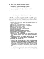
A good preinstallation program should accomplish the following:
1.
Inspect all equipment upon arrival for any shipping damage.
2.
Ensure good lifting practices are followed when transporting all
equipment; a pressure gauge makes a vulnerable spot to place a lift-
ing strap while off-loading a pump.
3.
All nozzles and openings should be kept covered or plugged until
piping is attached. Besides keeping out the elements, this will pre-
vent foreign material such as welding rods, rags, waste paper, etc.,
from getting in the machine and causing damage. Disassembling a
pump during a unit start-up to remove debris can be quite expen-
sive.
4.
If more than
six
months will pass before the equipment is expected
to run, consideration should be given to respraying the pump inter-
nals with a suitable rust preventive. Better yet, the pump could be
preserved by the application of oil mist. Ensure that whatever is
used is compatible with any elastomers it may come in contact with,
is
easily removable, and is applied according to manufacturer’s in-
structions.
5.
Fill all oil-lubricated bearings with the proper lube oil as soon as
possible. If the bearing is to be oil mist lubricated, consider attach-
ing and using the oil mist generator during the construction phase of
the project. If not, fill those bearings with oil also. Greased bear-
ings present a different problem. All greased bearings should be re-
packed with the correct grease as soon as possible. Follow manu-
facturer’s instructions; however, ensure that
all
the old grease is
displaced by the new grease. Different greases have different addi-
tives that normally
are
not compatible with each other. Mixing two
noncompatible greases will reduce the beneficial properties of ei-
ther grease.
6.
Coat all exposed machined surfaces with either a rust preventive or
grease to protect them from the environment.
7.
In order to prevent corrosion of the shaft sleeve, packed pumps re-
ceived with the packing installed should have the packing com-
pletely removed immediately on arrival and the shaft sleeve and
gland greased. Normally, packed pumps are shipped with an extra
set of packing. Of course, just before starting, this packaging
should be installed in the pump.
8.
Likewise, steam turbines received with the carbon rings installed
should have the rings removed immediately on arrival and the shaft
greased. The rings should then be reinstalled just prior to start-up.
Caution should be taken when removing and installing rings. Axial
ring orientation and location as well as the direction of shaft rota-
Installation, Maintenance, and Repair
of
Horizontal
Pumps
9
tion is critical. Be sure to consult the manufacturer's instruction
manual for details.
9.
Pump mechanical seals are precision components and therefore re-
quire special handling during transport and installation. When mov-
ing pumps with seals, the pumps should be securely restrained to
prevent excessive vibration and/or damage to the shaft and seal by
dropping or bumping the shaft. When installing or lifting the pump,
do not use the shaft as a leverage or lifting point.
On new installations, if a mechanical seal is to fail, it normally
will do
so
within the first few hours of operation. The primary
causes can often be traced to improper installation of the seals, or
mishandling of
seals
during pump installation.
Foundation And Anchor
Bolts
The design of equipment foundations and the different characteristics
of concrete and grouts are thoroughly discussed in Volume
3
of this se-
ries,
so
we will not go into great detail here. However, there are some
general guidelines to follow that will ensure a good installation.
1. Assuming that the forms and steel reinforcing rods are all sized and
placed according to approved drawings, the next most important
step is the placement of the anchor bolts. Prior to the actual con-
crete pour the anchor bolts should be:
a. Accurately set according to the foundation drawings and firmly
secured to prevent shifting during the pouring process.
b. Dimensionally checked (and rechecked) versus the foundation
drawings for proper length, diameter, thread length, etc.
c. Checked for proper projection; Le., checked for correct eleva-
tions as referenced to an established benchmark. It can be very
embarrassing to set a baseplate on a new foundation and find that
the anchor bolts are not long enough to pass through the base-
plate and the hold-down mats.
d. Install metal or plastic anchor bolt sleeves. Remember, sleeves
are not intended to encourage careless positioning
of
the anchor
bolts. However, they will allow for slight errors in baseplate
hole layouts and small shifting of the anchor bolt during the con-
crete pouring process.
e. Ensure that the exposed threads are protected by coating with
heavy grease or with paste wax. The exposed bolts should be
covered with plastic wrap and the wrap firmly secured with
wire.
10
Major Process Equipment Maintenance and Repair
2.
After the pour, the surface of the foundation should be chipped to
remove all laitance and defective or weak concrete. Normally, a
chipping hammer should be used; sand blasting or using a needle
gun is not effective. The amount of concrete removed should be
such that the final baseplate
or
soleplate elevation allows for one to
two inches of grout between the surface of
the
foundation and the
lower baseplate flange or the underside of the soleplates. After
chipping, the top surface should be reasonably level and free of all
oil, grease, and loose particles.
3.
Baseplates or soleplates should not be placed on the foundation until
a minimum of ten days has elapsed after pouring the normal con-
crete. High early-strength concrete may be used
in
some specific
applications but is not usually required. In any event, baseplates
and soleplates should not be placed on foundations until the con-
crete has had time to
dry
and cure
so
that
85
percent of the shrink-
age has taken place.
4.
Protect the surface of the foundation according to the type of grout
to be used. When using epoxy grout, the concrete surface must be
dry at the time the grout is applied. When using cement-based
grout, keep the foundation wet for the period of time recommended
by the grout manufacturer prior to grouting.
5.
If used, remove the tops of the plastic anchor bolt sleeves and en-
sure that the sleeves are
free
of foreign material.
Baseplate and Soleplate Preparation
1.
While the practice varies from company to company, it is suggested
that
all
equipment be removed from its baseplate or soleplate prior
to grouting. This aids in leveling the plate and prevents unwanted
distortion
of
the baseplate. The machinery can easily be reinstalled
after the baseplate
or
soleplate has been grouted.
2.
Normally, baseplates and soleplates are provided
by
the equipment
supplier and manufactured in accordance with some company or in-
dustrial specification. The installing agency must inspect and verify
that the baseplate or soleplate
is
in accordance with these specifica-
tions but, as a minimum, it should have the following:
a.
All
baseplate and soleplate surfaces (except on mounting pads
and
in threaded holes but including
the
outside edges) that will
be
in contact with the grout should be coated
with
an inorganic zinc
silicate
or
other primer compatible with the grout being used.
Base metal, blistered, or rusted surfaces are unacceptable.