ISO 251783:2012 Geometrical product specifications (GPS) — Surface texture: Areal — Part 3: Specification operators
Bạn đang xem bản rút gọn của tài liệu. Xem và tải ngay bản đầy đủ của tài liệu tại đây (216.81 KB, 26 trang )
INTERNATIONAL ISO
STANDARD 25178-3
First edition
2012-07-01
Geometrical product specifications
(GPS) — Surface texture: Areal —
Part 3:
Specification operators
Spécification géométrique des produits (GPS) — État de surface:
Surfacique —
Partie 3: Opérateurs de spécification
Reference number
ISO 25178-3:2012(E)
© ISO 2012
ISO 25178-3:2012(E)
COPYRIGHT PROTECTED DOCUMENT
© ISO 2012
All rights reserved. Unless otherwise specified, no part of this publication may be reproduced or utilized in any form or by any means,
electronic or mechanical, including photocopying and microfilm, without permission in writing from either ISO at the address below or ISO’s
member body in the country of the requester.
ISO copyright office
Case postale 56 • CH-1211 Geneva 20
Tel. + 41 22 749 01 11
Fax + 41 22 749 09 47
Web www.iso.org
Published in Switzerland
ii © ISO 2012 – All rights reserved
ISO 25178-3:2012(E)
Contents Page
Foreword ............................................................................................................................................................................ iv
Introduction ........................................................................................................................................................................ v
1 Scope ...................................................................................................................................................................... 1
2 Normative references ......................................................................................................................................... 1
3 Terms and definitions......................................................................................................................................... 1
4 Complete specification operator..................................................................................................................... 2
4.1 General ................................................................................................................................................................... 2
4.2 Method of extraction........................................................................................................................................... 2
4.3 Association method............................................................................................................................................ 6
4.4 Filtration................................................................................................................................................................. 6
4.5 Definition area ...................................................................................................................................................... 7
5 General information ............................................................................................................................................ 7
Annex A (informative) Decision tree for complete specification operator .......................................................... 8
Annex B (normative) Default attribute values for parameters from ISO 25178-2.............................................. 9
Annex C (normative) Default units for parameters from ISO 25178-2................................................................ 11
Annex D (informative) Relationship with surface texture profile parameters .................................................. 14
Annex E (informative) Relation to the GPS matrix model...................................................................................... 16
Bibliography ..................................................................................................................................................................... 18
© ISO 2012 – All rights reserved iii
ISO 25178-3:2012(E)
Foreword
ISO (the International Organization for Standardization) is a worldwide federation of national standards bodies
(ISO member bodies). The work of preparing International Standards is normally carried out through ISO
technical committees. Each member body interested in a subject for which a technical committee has been
established has the right to be represented on that committee. International organizations, governmental and
non-governmental, in liaison with ISO, also take part in the work. ISO collaborates closely with the International
Electrotechnical Commission (IEC) on all matters of electrotechnical standardization.
International Standards are drafted in accordance with the rules given in the ISO/IEC Directives, Part 2.
The main task of technical committees is to prepare International Standards. Draft International Standards
adopted by the technical committees are circulated to the member bodies for voting. Publication as an
International Standard requires approval by at least 75 % of the member bodies casting a vote.
Attention is drawn to the possibility that some of the elements of this document may be the subject of patent
rights. ISO shall not be held responsible for identifying any or all such patent rights.
ISO 25178-3 was prepared by Technical Committee ISO/TC 213, Dimensional and geometrical product
specifications and verification.
ISO 25178 consists of the following parts, under the general title Geometrical product specifications (GPS) —
Surface texture: Areal:
— Part 2: Terms, definitions and surface texture parameters
— Part 3: Specification operators
— Part 6: Classification of methods for measuring surface texture
— Part 70: Physical measurement standards
— Part 71: Software measurement standards
— Part 601: Nominal characteristics of contact (stylus) instruments
— Part 602: Nominal characteristics of non-contact (confocal chromatic probe) instruments
— Part 603: Nominal characteristics of non-contact (phase-shifting interferometric microscopy) instruments
— Part 604: Nominal characteristics of non-contact (coherence scanning interferometry) instruments
— Part 701: Calibration and measurement standards for contact (stylus) instruments
The following parts are under preparation:
— Part 1: Indication of surface texture
— Part 605: Nominal characteristics of non-contact (point autofocus probe) instruments
— Part 606: Nominal characteristics of non-contact (focus variation) instruments
iv © ISO 2012 – All rights reserved
ISO 25178-3:2012(E)
Introduction
This part of ISO 25178 is a geometrical product specification (GPS) standard and is to be regarded as a general
GPS standard (see ISO/TR 14638). It influences the chain link 3 of the chains of standards on areal surface texture.
The ISO/GPS Masterplan given in ISO/TR 14638 gives an overview of the ISO/GPS system of which this
document is a part. The fundamental rules of ISO/GPS given in ISO 8015 apply to this document and the
default decision rules given in ISO 14253-1 apply to specifications made in accordance with this document,
unless otherwise indicated.
For more detailed information on the relation of this part of ISO 25178 to the GPS matrix model, see Annex E.
This part of ISO 25178 specifies the specification operators according to ISO 17450-2.
© ISO 2012 – All rights reserved v
INTERNATIONAL STANDARD ISO 25178-3:2012(E)
Geometrical product specifications (GPS) — Surface texture:
Areal —
Part 3:
Specification operators
1 Scope
This part of ISO 25178 specifies the complete specification operator for surface texture (scale limited surfaces)
by areal methods.
2 Normative references
The following referenced documents are indispensable for the application of this standard. For dated references,
only the cited editions apply. For undated references, the latest edition of the referenced document (including
any amendments) applies.
ISO 14406:2010, Geometrical Product Specifications (GPS) — Extraction
ISO 14660-1:1999, Geometrical Product Specifications (GPS) — Geometrical features — Part 1: General
terms and definitions
ISO/TS 16610-1:2006, Geometrical Product Specifications (GPS) — Filtration — Part 1: Overview and
basic concepts
ISO 16610-21:2011, Geometrical product specifications (GPS) — Filtration — Part 21: Linear profile filters:
Gaussian filters
ISO 17450-1:2011, Geometrical Product Specifications (GPS) — General concepts — Part 1: Model for
geometrical specification and verification
ISO 17450-2:— 1), Geometrical Product Specifications (GPS) — General concepts — Part 2: Basic tenets,
specifications, operators, uncertainties and ambiguities
ISO 25178-2:2012, Geometrical Product Specifications (GPS) — Surface texture: Areal — Part 2: Terms.
definitions and surface texture parameters
3 Terms and definitions
For the purposes of this document, the terms and definitions given ISO 14660-1, ISO 16610-1, ISO/TS 14406,
ISO 17450-1, ISO 17450-2 and ISO 25178-2 and the following apply.
3.1
lateral period limit
<optical> spatial period of a sinusoidal profile at which the optical response falls to 50 %
NOTE The lateral period limit depends on the heights of surface features and the optical method used to probe the surface.
1) To be published.
© ISO 2012 – All rights reserved 1
ISO 25178-3:2012(E)
4 Complete specification operator
4.1 General
The complete specification operator (see ISO 17450-2) consists of all the operations required for an unambiguous
specification. It consists of a full set of unambiguous specification operations in an unambiguous order. For
areal surface texture, the complete specification operator defines the type of surface, method of extraction,
association method and filtration for surface texture by areal methods.
If form error is to be included in the measurand, then a S-F surface shall be specified; otherwise, an S-L
surface shall be specified.
4.2 Method of extraction
4.2.1 Evaluation area
4.2.1.1 General
The evaluation area consists of a rectangular portion of the surface over which an extraction is made.
The orientation of the evaluation area shall be controlled by the specification.
NOTE 1 If the nesting index is the same in orthogonal directions, then the orientation does not matter.
NOTE 2 The orientation of the evaluation area is typically influenced by the form; this means that the sides of the
rectangular area are parallel/orthogonal to the nominal geometry (e.g. cylinder axis, sides of a rectangular flat, etc.).
4.2.1.2 S-F surface
For an S-F surface, if not otherwise specified, the evaluation area shall be a square.
If the F-operation is a filtration operation, then the length of the sides of the square evaluation area is the same
length as the filter “nesting index”.
If the F-operation is an association operation, then the length of the side of the square evaluation area is used
as a substitute for the F-operation nesting index value. This chosen value for the F-operation nesting index is
used for all subsequent operations.
The value of the nesting index for the F-operation is normally chosen from the following series:
...; 0,1 mm; 0,2 mm; 0,25 mm; 0,5 mm; 0,8 mm; 1,0 mm; 2,0 mm; 2,5 mm; 5,0 mm; 8,0 mm; 10 mm; ...
NOTE 1 An example of an F-operation with a nesting index is a spline filter. The total least squares fit of the nominal
form is an example of an F-operation without a predefined nesting index.
NOTE 2 The value of the F-operation nesting index is typically chosen to be five times the scale of the coarsest
structure of interest.
4.2.1.3 S-L surface
For an S-L surface, if not otherwise specified, the evaluation area shall be a square whose sides are the same
length as the L-filter nesting index value.
The value of the nesting index for the L-filter is normally chosen from the following series:
...., 0,1 mm; 0,2 mm; 0,25 mm; 0,5 mm; 0,8 mm; 1,0 mm; 2,0 mm;2,5 mm; 5,0 mm; 8,0 mm; 10 mm; ...
NOTE The value of the L-filter nesting index is typically five times the scale of the coarsest structure of interest.
2 © ISO 2012 – All rights reserved
ISO 25178-3:2012(E)
4.2.2 Type of surface
The default surface is the mechanical surface (see ISO 14406) obtained with a radius chosen in accordance
with the F-operation or L-filter and S-filter nesting index values given in Tables 1 and 2.
© ISO 2012 – All rights reserved 3
ISO 25178-3:2012(E)
Table 1 — Relationships between the F-operation or L-filter and S-filter nesting index values and the
bandwidth ratio
F-operation or S-filter nesting index Approximate bandwidth ratio between
L-filter nesting value the
index value mm F-operation or L-filter and S-filter
mm … nesting index values
… 0,001
0,1 0,000 5 …
0,000 2 100:1
0,2 0,000 1 200:1
0,002 500:1
0,25 0,001 1 000:1
0,000 5 100:1
0,5 0,000 2 200:1
0,002 5 400:1
0,8 0,000 8 1 000:1
0,000 25 100:1
1 0,005 300:1
0,002 1 000:1
2 0,001 100:1
0,000 5 250:1
2,5 0,008 500:1
0,002 5 1 000:1
5 0,000 8 100:1
0,01 300:1
8 0,005 1 000:1
… 0,002 100:1
0,001 200:1
0,02 500:1
0,01 1 000:1
0,005 100:1
0,002 200:1
0,025 400:1
0,008 1 000:1
0,002 5 100:1
0,05 300:1
0,02 1 000:1
0,01 100:1
0,005 250:1
0,08 500:1
0,025 1 000:1
0,008 100:1
… 300:1
1 000:1
…
4 © ISO 2012 – All rights reserved
ISO 25178-3:2012(E)
4.2.3 S-filter
4.2.3.1 General
The default S-filter is an areal Gaussian filter. The value of the S-filter nesting index (cut-off) (see ISO/TS 16610-
1) in the x-direction/y-direction is normally chosen from the following series:
...., 0,000 5 mm; 0,000 8 mm; 0,001 mm; 0,002 mm; 0,002 5 mm; 0,005 mm; 0,008 mm; 0,01 mm; ...
4.2.3.2 S-filter relationships for mechanical surfaces
For mechanical surfaces, the maximum values for the sampling distance and sphere radius are calculated from
the value of the S-filter nesting index, as given in Table 2.
Table 2 — Relationships between S-filter nesting index value, sampling distance and sphere radius
for mechanical surface
S-filter nesting index value Maximum sampling Maximum sphere
distance radius
mm mm mm
...
0,000 1 ... ...
0,000 2 0,000 02 0,000 07
0,000 25 0,000 04 0,000 14
0,000 5 0,000 05 0,000 2
0,000 8 0,000 1 0,000 35
0,001 0,000 15 0,000 5
0,002 0,000 2 0,000 7
0,002 5 0,000 4 0,001 4
0,005 0,000 5 0,002
0,008 0,001 0,003 5
0,01 0,001 5 0,005
0,02 0,002 0,007
0,025 0,004 0,014
0,050 0,005 0,02
0,08 0,01 0,035
0,1 0,015 0,05
0,2 0,02 0,07
0,25 0,04 0,14
... 0,05 0,2
... ...
NOTE 1 Starting with the value of the S-filter nesting index, the maximum sampling distance is calculated as a 5:1 ratio;
the maximum sphere ratio is calculated as an approximately 1,4:1 ratio with the S-filter nesting index value. These ratios
are consistent with those contained in ISO 3274:1996.
NOTE 2 The maximum sampling distances in Table 2 are considered ideal and may not be attainable for a given
surface and instrument type combination.
4.2.3.3 S-filter relationships for optical surfaces
For optical surfaces (electromagnetic surfaces), the maximum values for the sampling distance and lateral
period limit are related to the value of the S-filter nesting index as given in Table 3.
© ISO 2012 – All rights reserved 5
ISO 25178-3:2012(E)
Table 3 — Relationships between S-filter nesting index value, sampling distance and the lateral
period limit for optical surface
S-filter nesting index value a Maximum sampling Maximum lateral period
distance limit
mm mm mm
… … …
0,000 1 0,000 03 0,000 1
0,000 2 0,000 06 0,000 2
0,000 25 0,000 08 0,000 25
0,000 5 0,000 15 0,000 5
0,000 8 0,000 25 0,000 8
0,001 0,000 3 0,001
0,002 0,000 6 0,002
0,002 5 0,000 8 0,002 5
0,005 0,001 5 0,005
0,008 0,002 5 0,008
0,01 0,003 0,01
0,02 0,006 0,02
0,025 0,008 0,025
0,05 0,015 0,05
0,08 0,025 0,08
0,1 0,03 0,1
0,2 0,06 0,2
0,25 0,08 0,25
… … …
a Alternatively, the optical method used to probe the surface may provide an inherent
filter giving rise to the lateral period limit that approximates a Gaussian filter; in these
cases, the lateral period limit may be used to define the short-wavelength nesting index
instead of a digital S-filter.
NOTE 1 Starting with the value of the S-filter nesting index, the maximum sampling distance is calculated as a 3:1 ratio;
the maximum lateral period limit is calculated as an approximately 1:1 ratio with the S-filter nesting index value.
NOTE 2 The maximum sampling distances in Table 3 are considered ideal and may not be attainable for a given
surface and instrument type combination.
4.3 Association method
When applying an F-operation that requires a method of association, the default method of association is total
least squares.
4.4 Filtration
4.4.1 General
The filtration depends on the type of surface (S-L surface or S-F surface) specified.
For an S-L surface, both an L-filter and an F-operation are specified. For an S-F surface, only an F-operation
is specified.
6 © ISO 2012 – All rights reserved
ISO 25178-3:2012(E)
4.4.2 F-operation
The form shall be removed using a feature of the same class as the nominal form with the default association method.
NOTE 1 For features of size, the size is variable in the default association operation.
NOTE 2 For non-default form removal, a filtration method according to the ISO 16610 series can also be used. A
filtration masterplan of all these filtration methods can be found in ISO/TS 16610-1.
4.4.3 L-filter
The default L-filter is an areal Gaussian filter (see ISO 16610-21). The nesting index in the x-direction/y-direction
is a mandatory part of the specification of the S-L surface.
4.5 Definition area
4.5.1 S-L surface
The default definition area for the S-L surface is a square with the same size as the evaluation area.
4.5.2 S-F surface
The default definition area for the S-F surface is a square with the same size as the evaluation area.
5 General information
A decision tree for the complete specification operator is given in Annex A. If not otherwise specified, the
default attribute values for the parameters defined in ISO 25178-2 that shall be applied are given in Annex B.
If not otherwise specified, the default units for parameters defined in ISO 25178-2 that shall be used are given
in Annex C. The compatibility with surface texture profile parameters is given in Annex D. The relation to the
GPS matrix model is given in Annex E.
© ISO 2012 – All rights reserved 7
ISO 25178-3:2012(E)
Annex A
(informative)
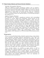
Decision tree for complete specification operator
Start
Form
deviation
Y included in N
measurand
Use Use
S-F surface S-L surface
Evaluation Attribute Value
Area Orientation Controlled by the specification
Shape Rectangular, Default shape square
Default S-F Surface: F-operation nesting index value
size S-L Surface: L-filter nesting index value
Table 1 Attribute Value
Default Gaussian filter
S-filter type User specified
Given in Table 1
S-filter
Nesting index value
bandwidth ratio
Mechanical surface Surface Optical surface
Default surface type type
Table 2 Mechanical surface Table 3 Optical surface
Attribute Value Attribute Value
Max sampling distance Defined from S-filter Max sampling distance Defined from S-filter
nesting index value nesting index value
Max sphere radius Defined from S-filter Max lateral period limit Defined from S-filter
nesting index value nesting index value
Figure A.1 — Decision tree for a complete specification operator
NOTE The order in which the attribute values for the GPS operations are determined does not reflect the order in
which the GPS operations are implemented.
8 © ISO 2012 – All rights reserved
ISO 25178-3:2012(E)
Annex B
(normative)
Default attribute values for parameters from ISO 25178-2
B.1 Field parameters
B.1.1 Spatial parameters
Paragraph in Parameter Attribute Default value
ISO 25178-2: (abbreviated
fastest decay to a specified value s, with 0 ≤ s < 1 s is 0,2
2012 term) fastest and slowest decays to s, with 0 ≤ s < 1 s is 0,2
4.2.1 Sal Default value
4.2.2 Str p is 80 %
p is 10 %
B.1.2 Functions and related parameters q is 80 %
p is 10 %
Paragraph in Parameter Attribute p is 10 %
ISO 25178-2: (abbreviated q is 80 %
material ratio p p is 2,5 %
2012 term) material ratios p and q q is 50 %
Th is 10 %
4.4.5.1 Vvv
4.4.5.2 Vvc
4.4.6.1 Vmp material ratio p
4.4.6.2 Vmc material ratios p and q
4.4.7 Sxp material ratios p and q
4.4.9.8 SRC Threshold, Th
© ISO 2012 – All rights reserved 9
ISO 25178-3:2012(E)
B.2 Named feature parameters
Paragraph in Parameter Attribute Default value
ISO 25178-2: (abbreviated
Wolfprune nesting index X % X % is 5 %
2012 term) Wolfprune nesting index X % X % is 5 %
Spd Wolfprune nesting index X % X % is 5 %
6.8.1 Spc Wolfprune nesting index X % X % is 5 %
S5p Wolfprune nesting index X % X % is 5 %
6.8.2 S5v The significant feature is
Sda(c) Closed.
6.8.3.1 X % is 5 %
The significant feature is
6.8.3.2 Closed.
X % is 5 %
6.8.4 The significant feature is
Closed.
6.8.5 Sha(c) Wolfprune nesting index X % X % is 5 %
The significant feature is
6.8.6 Sdv(c) Wolfprune nesting index X % Closed.
6.8.7 Shv(c) Wolfprune nesting index X %
10 © ISO 2012 – All rights reserved
ISO 25178-3:2012(E)
Annex C
(normative)
Default units for parameters from ISO 25178-2
C.1 Field parameters
C.1.1 Height parameters Parameter Default units
(abbreviated term)
4.1.1 Paragraph in
4.1.2 ISO 25178-2:2012
4.1.3
4.1.4 Sq µm
4.1.5
4.1.6 Ssk 1
4.1.7
Sku 1
Sp µm
Sv µm
Sz µm
Sa µm
C.1.2 Spatial parameters
Paragraph in Parameter Default units
ISO 25178-2:2012 (abbreviated term)
4.2.1 Sal µm
4.2.2 Str 1
4.5.1 Std degrees
C.1.3 Hybrid parameters Parameter Default units
(abbreviated term)
4.3.1 Paragraph in
4.3.2 ISO 25178-2:2012 Sdq
Sdr
radians
%
© ISO 2012 – All rights reserved 11
ISO 25178-3:2012(E)
C.1.4 Functions and related parameters
Paragraph in Parameter Default units
ISO 25178-2:2012 (abbreviated term)
4.4.2 Smr(c) %
4.4.3
4.4.4 Sdc(mr) µm
4.4.4
4.4.4 Sk, Spk, Svk µm
4.4.7
Smr1, Smr2 %
Svq, Spq, Smq µm
Sxp µm
C.1.5 Void and material volume parameters
Paragraph in Parameter Default unitsa
ISO 25178-2:2012 (abbreviated term)
4.4.5 Vv(p) ml m−2
4.4.5.1 Vvv ml m−2
4.4.5.2 Vvc ml m−2
4.4.6 Vm(p) ml m−2
4.4.6.1 Vmp ml m−2
4.4.6.2 Vmc ml m−2
a The unit ml m−2 is used because oil is usually specified in litres and the amount of oil per square metre for typical applications is of
the order of one millilitre.
C.1.6 Other parameters
Paragraph in Parameter Default units
ISO 25178-2:2012 (abbreviated term)
4.4.9.4 Svfc 1
4.4.9.5
Safc 1
12 © ISO 2012 – All rights reserved
ISO 25178-3:2012(E)
C.2 Feature parameters
Paragraph in Parameter Default units
ISO 25178-2:2012 (abbreviated term)
6.8.1 Spd mm−2
6.8.2 Spc mm−2
6.8.3 S10z µm
6.8.3.1 S5p µm
6.8.3.2 S5v µm
6.8.4 Sda(c) µm 2
6.8.5 Sha(c) µm 2
6.8.6 Sdv(c) µm 3
6.8.7 Shv(c) àm3
â ISO 2012 All rights reserved 13
ISO 25178-3:2012(E)
Annex D
(informative)
Relationship with surface texture profile parameters
D.1 General
Surface texture has traditionally been defined from profiles. This reflects the limitations in technology, with only
profile measuring instruments being initially available2) . Technology has progressed and areal instruments are
now widely available. This has resulted in a paradigm shift from profile to areal3) and has led to the development
of this areal-surface-texture chain of standards.
With the long history and usage of profile parameters, knowledge has been built up and familiarity with profile
methods has developed; inevitably, with the introduction of areal parameters, a comparison between surface
texture profile and areal parameter values has resulted. This annex presents advice and guidelines on these
relationships and on the differences between profile-surface-texture and areal-surface-texture parameters and
their values.
D.2 Filtration
The biggest difference between profile and areal methods is in the filtration used. A profile extracted from an
S-L surface or an S-F surface is not mathematically the same as a profile measured according to the surface
texture profile chain of standards. The latter uses a profile filter (filtration in the traverse direction only, which is
orthogonal to the lay) and the former an areal filter (filtration in both the x- and y-directions which may or may
not be related to the lay direction), which can produce very different results even with the ‘same’ filter type and
cut-off/nesting index.
In practice, some surfaces can be very similar with profile filters and areal filters, but caution is advised. The
user has to have a real understanding of the difference and similarities between the effects from profile filters
and areal filters on the particular surface under investigation. Which features are affected by the difference,
and at what scales? Do they matter for the particular comparison?
To minimize the differences, it is recommended that
— the orientation of the rectangular portion of the surface, over which the measurement is made, be aligned
with the lay of the surface,
— a Gaussian filter be used with a recommended cut-off value given by the default values in the surface
texture profile chain of standards, i.e. from the series
...; 0,08 mm; 0,25 mm; 0,8 mm; 2,5 mm; 8,0 mm; ...,
— other default values, where appropriate, given in the surface texture profile chain of standards be used, i.e.
the default stylus tip radius, sampling spacing, etc.,
— the length of the “traverse” direction of the rectangular portion of the surface be five times the cut-off length.
2) See Reference [5] in the Bibliography. © ISO 2012 – All rights reserved
3) See References [6] and [7] in the Bibliography.
14