ISO 25780:2011 Plastics piping systems for pressure and nonpressure water supply, irrigation, drainage or sewerage — Glassreinforced thermosetting plastics (GRP) systems based on unsaturated polyester (UP) resin — Pipes with flexible joints intended to be
Bạn đang xem bản rút gọn của tài liệu. Xem và tải ngay bản đầy đủ của tài liệu tại đây (866.28 KB, 56 trang )
INTERNATIONAL ISO
STANDARD 25780
First edition
2011-05-15
Plastics piping systems for pressure and
non-pressure water supply, irrigation,
drainage or sewerage — Glass-reinforced
thermosetting plastics (GRP) systems
based on unsaturated polyester (UP)
resin — Pipes with flexible joints
intended to be installed using jacking
techniques
Systèmes de canalisations en matières plastiques pour l'alimentation
en eau avec ou sans pression, pour l'irrigation ou l'assainissement —
Systèmes en matières plastiques thermodurcissables renforcés de
verre (PRV) à base de résine de polyester non saturé (UP) — Tubes
avec assemblages flexibles destinés à être installés par les techniques
de poussée
Reference number
ISO 25780:2011(E)
© ISO 2011
ISO 25780:2011(E)
COPYRIGHT PROTECTED DOCUMENT
© ISO 2011
All rights reserved. Unless otherwise specified, no part of this publication may be reproduced or utilized in any form or by any means,
electronic or mechanical, including photocopying and microfilm, without permission in writing from either ISO at the address below or
ISO's member body in the country of the requester.
ISO copyright office
Case postale 56 • CH-1211 Geneva 20
Tel. + 41 22 749 01 11
Fax + 41 22 749 09 47
Web www.iso.org
Published in Switzerland
ii © ISO 2011 – All rights reserved
ISO 25780:2011(E)
Contents Page
Foreword ............................................................................................................................................................iv
1 Scope ......................................................................................................................................................1
2 Normative references............................................................................................................................1
3 Terms and definitions ...........................................................................................................................2
4 Requirements ....................................................................................................................................... 11
4.1 Classification .......................................................................................................................................11
4.2 Pipe properties ....................................................................................................................................11
4.3 Materials ...............................................................................................................................................12
4.4 Pipe wall construction ........................................................................................................................13
4.5 Reference conditions for testing .......................................................................................................14
4.6 Elapsed time, x, for determination of long-term properties ............................................................14
4.7 Joint properties ...................................................................................................................................14
5 Pipes .....................................................................................................................................................16
5.1 Geometrical characteristics ...............................................................................................................16
5.2 Mechanical characteristics.................................................................................................................19
5.3 Resistance to strain corrosion...........................................................................................................20
5.4 Longitudinal compressive strength ..................................................................................................20
5.5 Permissible jacking forces .................................................................................................................21
5.6 Specific initial longitudinal compressive modulus, Ec,m.................................................................23
5.7 Resistance of pressure pipes to internal pressure..........................................................................23
6 Marking .................................................................................................................................................23
7 Joint performance ...............................................................................................................................23
7.1 General requirements .........................................................................................................................23
7.2 Interchangeability................................................................................................................................24
7.3 Geometrical characteristics ...............................................................................................................24
7.4 Design...................................................................................................................................................24
7.5 Performance requirements.................................................................................................................24
7.6 Test method additional information ..................................................................................................25
Annex A (normative) Plastics piping systems — Glass-reinforced thermosetting plastics (GRP)
pipes — Determination of the longitudinal compressive properties of a pipe, using
a sample of prism test-pieces cut from a ring from the pipe..........................................................27
Annex B (normative) Plastics piping systems — Glass-reinforced thermosetting plastics (GRP)
pipes — Determination of the compressive properties of pipes, using spool test-pieces .........34
Annex C (normative) Procedure for the calculation of the permissible jacking force on a GRP-(UP)
pipe, Fperm,p ..........................................................................................................................................39
Bibliography ...................................................................................................................................................... 51
© ISO 2011 – All rights reserved iii
ISO 25780:2011(E)
Foreword
ISO (the International Organization for Standardization) is a worldwide federation of national standards bodies
(ISO member bodies). The work of preparing International Standards is normally carried out through ISO
technical committees. Each member body interested in a subject for which a technical committee has been
established has the right to be represented on that committee. International organizations, governmental and
non-governmental, in liaison with ISO, also take part in the work. ISO collaborates closely with the
International Electrotechnical Commission (IEC) on all matters of electrotechnical standardization.
International Standards are drafted in accordance with the rules given in the ISO/IEC Directives, Part 2.
The main task of technical committees is to prepare International Standards. Draft International Standards
adopted by the technical committees are circulated to the member bodies for voting. Publication as an
International Standard requires approval by at least 75 % of the member bodies casting a vote.
Attention is drawn to the possibility that some of the elements of this document may be the subject of patent
rights. ISO shall not be held responsible for identifying any or all such patent rights.
ISO 25780 was prepared by Technical Committee ISO/TC 138, Plastics pipes, fittings and valves for the
transport of fluids, Subcommittee SC 6, Reinforced plastics pipes and fittings for all applications.
iv © ISO 2011 – All rights reserved
INTERNATIONAL STANDARD ISO 25780:2011(E)
Plastics piping systems for pressure and non-pressure water
supply, irrigation, drainage or sewerage — Glass-reinforced
thermosetting plastics (GRP) systems based on unsaturated
polyester (UP) resin — Pipes with flexible joints intended to be
installed using jacking techniques
1 Scope
This International Standard specifies the properties of the piping system and its components made from glass-
reinforced thermosetting plastics (GRP) based on unsaturated polyester resin (UP) for water supply, irrigation,
drainage or sewerage systems with or without pressure.
This International Standard is applicable to GRP-UP piping systems, with flexible joints, intended to be
installed using jacking techniques. It specifies the characteristics of pipes made from GRP-UP, with or without
aggregates or fillers and also specifies the test parameters for the test methods referred to in this International
Standard.
NOTE Pipes referred to in this International Standard are, because of their intended use, required to have a minimum
nominal stiffness of at least SN 20000 (see 5.2.1).
This International Standard is applicable to pipes and joints with a size range from DN100 to DN4000 which
are intended to be used for the conveyance of water or sewage at temperatures up to 50 °C, with or without
pressure.
It covers requirements to prove the design of the joint and specifies type test performance requirements for
the joints as a function of the declared nominal pressure rating of the pipeline system and the required joint
deflection capability of the system.
GRP-fittings, used between pipe systems covered by this International Standard, shall be in accordance with
ISO 10639 for water supply systems or ISO 10467 for drainage and sewerage systems, as applicable. In a
pipe-work system, pipes of different nominal pressure and stiffness ratings may be used together.
2 Normative references
The following referenced documents are indispensable for the application of this document. For dated
references, only the edition cited applies. For undated references, the latest edition of the referenced
document (including any amendments) applies.
ISO 75-2:2004, Plastics — Determination of temperature of deflection under load — Part 2: Plastics and
ebonite
ISO 604:2002, Plastics — Determination of compressive properties
ISO 2078, Textile glass — Yarns — Designation
ISO 3126, Plastics piping systems — Plastics components — Determination of dimensions
© ISO 2011 – All rights reserved 1
ISO 25780:2011(E)
ISO 4633, Rubber seals — Joint rings for water supply, drainage and sewerage pipelines — Specification for
materials
ISO 7685, Plastics piping systems — Glass-reinforced thermosetting plastics (GRP) pipes — Determination of
initial specific ring stiffness
ISO 8639, Glass-reinforced thermosetting plastics (GRP) pipes and fittings — Test methods for leaktightness
of flexible joints
ISO 10466, Plastics piping systems — Glass-reinforced thermosetting plastics (GRP) pipes — Test method to
prove the resistance to initial ring deflection
ISO 10467, Plastics piping systems for pressure and non-pressure drainage and sewerage — Glass-
reinforced thermosetting plastics (GRP) systems based on unsaturated polyester (UP) resin
ISO 10468, Glass-reinforced thermosetting plastics (GRP) pipes — Determination of the long-term specific
ring creep stiffness under wet conditions and calculation of the wet creep factor
ISO 10471, Glass-reinforced thermosetting plastics (GRP) pipes — Determination of the long-term ultimate
bending strain and the long-term ultimate relative ring deflection under wet conditions
ISO 10639, Plastics piping systems for pressure and non-pressure water supply — Glass-reinforced
thermosetting plastics (GRP) systems based on unsaturated polyester (UP) resin
ISO 10928, Plastics piping systems — Glass-reinforced thermosetting plastics (GRP) pipes and fittings —
Methods for regression analysis and their use
ISO 10952, Plastics piping systems — Glass-reinforced thermosetting plastics (GRP) pipes and fittings —
Determination of the resistance to chemical attack for the inside of a section in a deflected condition
3 Terms and definitions
For the purposes of this document, the following terms and definitions apply.
3.1
manufacturer's declared pipe outside diameter
dOD
external diameter of the pipe barrel, excluding the spigot
NOTE Manufacturer's declared pipe outside diameter is expressed in millimetres (mm).
3.2
jacking diameter
de
calculated maximum outside diameter of the external profile of the pipe barrel at all cross-sections
Δ+
d e = d OD + (1)
where
∆+ is the plus tolerance on the outside diameter;
dOD is the manufacturer's declared outside diameter.
NOTE Jacking diameter, which is derived using the equation above, outside diameter and its tolerance are
expressed in millimetres (mm).
2 © ISO 2011 – All rights reserved
ISO 25780:2011(E)
3.3
mean diameter
dm
diameter of the circle corresponding with the middle of the pipe wall cross-section
NOTE Mean diameter is derived using the following equation with the outside diameter and wall thickness expressed
in millimetres (mm):
d m = d OD − e
where
e is the pipe's wall thickness;
dOD is the manufacturer's declared outside diameter.
3.4
internal diameter
ID
di
external diameter minus twice the wall thickness, e
NOTE 1 Internal diameter is derived using the following equation
d i = dOD − 2 × e
NOTE 2 Internal diameter, outside diameter and wall thickness are expressed in millimetres (mm).
3.5
spigot or groove diameter
dg
external diameter of the spigot [see Figure 1 a) diameter], or in the groove of the spigot [see Figure 1 b)
diameter, if applicable]
NOTE Spigot or groove diameter is expressed in millimetres (mm).
3.6
minimum cross-sectional area at the spigot
As
minimum area of the cross-section of the pipe at the spigot, or in the groove of the spigot, if applicable
NOTE Minimum cross-sectional area at the spigot is derived using the following equation and is expressed in square
millimetres (mm2)
⎡ 2 2⎤
As = π ⎢(0,5 ⋅ d g ) − (0,5 ⋅ d i ) ⎥
⎣ ⎦
3.7
buried pipeline
pipeline which is subjected to the external pressure transmitted from soil loading, including traffic and
superimposed loads and, possibly, the pressure of a head of water
3.8
jacking
trenchless construction method which installs a pipeline by inserting pipes one by one under the ground by
pressing with one or more hydraulic jacks, while the excavated ground is simultaneously evacuated from the
cutting head
3.9
nominal length
numerical designation of a pipe length, which is numerically equal to the laying length (3.11), when expressed
in metres (m) and rounded to the nearest whole number
NOTE Nominal length is a dimensionless number rounded to the nearest whole number.
© ISO 2011 – All rights reserved 3
ISO 25780:2011(E)
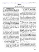
a) Section through a rebated un-grooved spigot b) Section through a rebated grooved spigot
c) Cross-section through spigot
Key
dOD outside diameter of pipe (see 3.1)
de jacking diameter (see 3.2)
di internal diameter of pipe (see 3.4)
dg rebated spigot or groove diameter (see 3.5)
e wall thickness of pipe
As Minimum pipe cross-sectional area at spigot (see 3.6).
Figure 1 — Diameters referred to in these definitions
3.10
total length
distance between two planes normal to the pipe axis and passing through the extreme end points of the pipe
NOTE Total length is expressed in metres (m).
4 © ISO 2011 – All rights reserved
ISO 25780:2011(E)
3.11
laying length
l
total length of a pipe minus, where applicable, the manufacturer's recommended insertion depth of the
spigot(s) in the socket
NOTE Laying length is expressed in millimetres (mm).
3.12
specific initial longitudinal compressive stress at break (derived from a spool test-piece)
σ b,s
compressive stress at break (3.46) of a spool test-piece, during a short-term compressive test with the test-
piece loaded along its longitudinal axis, including, if applicable, spigots with rebates
NOTE When tested in accordance with Annex B, specific initial longitudinal compressive stress is expressed in
megapascals (MPa).
3.13
minimum specific initial longitudinal compressive stress at break
σ b,s,min
manufacturer's declared minimum value for the specific initial longitudinal compressive stress at break of the
pipe
NOTE Minimum specific initial longitudinal compressive stress at break is expressed in megapascals (MPa).
3.14
initial longitudinal compressive stress at break (derived from rebated or un-rebated test-pieces)
σ b,r
σ b,u
compressive stress at break of the test-piece during a short-term compression test using either a rebated (r)
or unrebated (u) test-piece
NOTE When tested in accordance with Annex A, the initial longitudinal compressive stress at break is expressed in
megapascals (MPa).
3.15
sample de-rating factor
fs
factor correcting for the relationship between compression test results obtained on full size pipes (spool
test-pieces, 3.12) and results obtained using test-pieces with the same spigot geometry (3.14)
NOTE Sample derating factor is a dimensionless number.
3.16
de-rated initial longitudinal compressive stress at break
σ b,d
calculated compressive stress obtained from the test results at break using either un-rebated or rebated test-
pieces and the applicable de-rating factor
NOTE Derated initial longitudinal compressive stress at break is expressed in megapascals (MPa).
3.17
initial longitudinal compressive modulus
Ec,m
ratio of the applied stress to the resulting strain below the elastic limit, both measured concurrently during a
short-term compression test
NOTE When tested in accordance with either Annex A or B, the initial longitudinal compressive modulus is expressed
in megapascals (MPa).
© ISO 2011 – All rights reserved 5
ISO 25780:2011(E)
3.18
ultimate longitudinal load
Fult
calculated value of the concentric longitudinal load that the pipe withstands just before break
NOTE Ultimate longitudinal load is expressed in kilonewtons (kN).
3.19
longitudinal compressive (material) safety coefficient
γ
safety factor applied to the ultimate longitudinal load to determine the theoretical design jacking load Fj, calc
(3.21)
3.20
design jacking load
Fj
manufacturer's declared value of the longitudinal compressive load that a pipe can withstand during a jacking
operation, taking into account the material safety coefficient, γ
NOTE Design jacking load is expressed in kilonewtons (kN).
3.21
theoretical design jacking load
Fj, calc
calculated value of the concentric longitudinal compressive load that the pipe can be expected to withstand
during a jacking operation, taking into account the material safety coefficient, γ
NOTE Theoretical design jacking load is expressed in kilonewtons (kN).
3.22
permissible eccentric jacking force on the pipe
Fperm, p
calculated value of the permissible eccentric longitudinal load that the pipe can withstand during a jacking
operation, taking into account the material safety coefficient, γ (3.19), and the estimated angular deflection, δ
NOTE Permissible eccentric jacking force on the pipe is expressed in kilonewtons (kN).
3.23
permissible eccentric jacking force on the system
Fperm, s
value declared by the pipe manufacturer of the permissible eccentric longitudinal force that the system can
withstand during a jacking operation, taking into account the material safety coefficient, γ, and the estimated
angular deflection, δ
NOTE Permissible eccentric jacking force on the system is expressed in kilonewtons (kN).
3.24
nominal stiffness
SN
SN
alphanumerical designation for stiffness identification purposes (see 4.2.3), which has the same numerical
value as the minimum initial specific ring stiffness value, when expressed in newtons per square metre (N/m2)
NOTE Nominal stiffness is a dimensionless number used for identification or marking purposes consisting of the
letters SN plus a number.
6 © ISO 2011 – All rights reserved
ISO 25780:2011(E)
3.25
specific ring stiffness
S
physical characteristic of the pipe which is a measure of the resistance to ring deflection per metre length
under external load
NOTE Specific ring stiffness is determined using the following equation and is expressed in newtons per square
metre (N/m2)
S = E×I
d m3
where
E is the apparent modulus of elasticity, which can be derived from the result of the ring stiffness test, i.e. ISO 7685,
expressed in newtons per square metre (N/m2);
dm is the mean diameter of the pipe (3.3), in metres (m);
I is the second moment of area in the longitudinal direction per metre length, in metres to the fourth power per
metre, (m4/m)
I = e3
12
where e is the wall thickness, in metres (m).
3.26
initial specific ring stiffness
S0
value of specific ring stiffness, S, obtained when tested in accordance with ISO 7685
NOTE Initial specific ring stiffness is expressed in newtons per square metre (N/m2).
3.27
wet creep factor
α x,creep,wet
ratio of the long-term specific ring stiffness, Sx,wet at x years, to the initial specific ring stiffness, S0
NOTE When tested in accordance with ISO 10468, using sustained loading under wet conditions, the long-term
specific ring stiffness, Sx,wet is obtained and when this value is divided by the initial specific ring stiffness, S0, the wet creep
factor, αx,creep,wet, is obtained (see the following equation)
α x,creep,wet = S x,wet
S0
3.28
calculated long-term specific ring stiffness
Sx, wet
calculated value of specific ring stiffness, S, at x years
NOTE Long-term specific ring stiffness is obtained using the following equation
S x, wet = S 0 × α x, wet
where
x is the elapsed time in years specified in this International Standard (see 4.6);
αx,wet is the wet creep factor at x years;
S0 is the initial specific ring stiffness.
© ISO 2011 – All rights reserved 7
ISO 25780:2011(E)
3.29
pressure pipe
pipe having a nominal pressure (PN) (3.31) classification greater than 1 bar and which is intended to be used
with the internal pressure equal to or less than its nominal pressure when expressed in bars
3.30
non-pressure pipe
pipe subjected to an internal pressure not greater than 1 bar
3.31
nominal pressure
PN
alphanumeric designation for pressure classification purposes, which has a numerical value equal to the
resistance of a component of a piping system to internal pressure
NOTE Nominal pressure is a designation for reference or marking purposes that consists of the letters PN plus a
number which is related to a component's pressure rating in bars.
3.32
normal service conditions
conveyance of water or sewage, in the temperature range 2 °C to 50 °C, with or without pressure, for 50 years
3.33
design service temperature
maximum sustained temperature, at which the system is expected to operate continuously
NOTE Design service temperature is expressed in degrees Celsius (°C).
3.34
rerating factor
RRF
multiplication factor that quantifies the relation between a mechanical, physical or chemical property at the
service condition compared to the respective value at 23 °C and 50 % relative humidity (RH)
3.35
relative ring deflection
y /dm
ratio of the change in diameter of a pipe, y, in metres, to its mean diameter, dm, in metres
NOTE Relative ring deflection is derived as a percentage, %, i.e.:
⎛ y⎞
⎜⎜ ⎟ ⎝ d m ⎟ ×100 ⎠
3.36
minimum initial relative specific ring deflection at 2 min before bore cracking occurs
( y 2,bore d m ) min
initial relative specific ring deflection at 2 min which a test-piece is required to exceed without bore cracking
when tested in accordance with ISO 10466
NOTE Minimum initial relative specific ring deflection at 2 min before bore cracking occurs is expressed in % of mean
diameter, i.e.:
⎛ y 2, bore ⎞
⎜ ⎟ × 100
⎜ dm ⎟
⎝ ⎠ min
8 © ISO 2011 – All rights reserved
ISO 25780:2011(E)
3.37
type test
tests carried out in order to assess the fitness for purpose of a product or assembly of components to fulfil its
or their function(s) in accordance with this International Standard
3.38
flexible joint
joint which allows relative movement between components being joined
3.39
flush coupling
joint component with either an external diameter equal to the pipe's outside diameter or an inside diameter
equal to the pipe's inside diameter
3.40
closed joint
joint condition where the pipe-ends, initially separated with a pressure transfer ring, are in close contact with
each other without any gap around the whole circumference
3.41
open joint
joint condition where the pipe-ends are partly or totally not in close contact with each other thereby forming a
gap
3.42
angular deflection
δ
angle between the axes of two adjacent pipes
NOTE Angular deflection (see Figure 2) is expressed in degrees (°).
3.43
draw
D
longitudinal movement of a joint
NOTE Draw (see Figure 2) is expressed in millimetres (mm).
3.44
total draw
T
sum of the draw, D, and the additional longitudinal movement, J, due to the presence of angular deflection
NOTE Total draw (see Figure 2) is expressed in millimetres (mm).
3.45
misalignment
M
amount by which the centrelines of adjacent pipes fail to coincide
NOTE Misalignment (see Figure 2) is expressed in millimetres (mm).
3.46
break
condition where the test-piece can no longer carry the load to which it is being subjected
© ISO 2011 – All rights reserved 9
ISO 25780:2011(E)
3.47
overcut
area between the bored wall formed in the native soil and the external surface of the pipe, created by the
cutting head or shield of the jacking machine
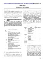
a)
b)
c)
Figure 2 — Joint movements (continued)
10 © ISO 2011 – All rights reserved
ISO 25780:2011(E)
d)
Key
D draw
J longitudinal movement arising from angular deflection of the joint
δ angular deflection of the joint
T total draw
M misalignment
NOTE The joint in this figure is an example of a typical joint but is not intended to fix design. Other joints are available.
Figure 2 — Joint movements
4 Requirements
4.1 Classification
Pipes shall be identified according to the manufacturer's declared pipe outside diameter, dOD (see 3.1),
maximum jacking load (see 4.1.3), nominal stiffness (SN) (see 3.24), nominal pressure (PN) (see 3.31) and
joint type (see 4.2.2).
Couplings for use on the outside of a pipe shall be identified according to the pipe jacking diameter, de,
nominal pressure (PN) and joint type. Couplings for use on the inside of a pipe shall be identified according to
the pipe's internal diameter, di (see 3.4), nominal pressure (PN) and joint type.
4.2 Pipe properties
4.2.1 Manufacturer's declared diameters
The outside diameter of GRP pipes conforming with this International Standard shall conform to the
requirements given in Table 4 and be designated by the manufacturer's declared pipe outside diameter, dOD
(see 3.1). The manufacturer shall also declare the internal diameter, di (see 3.4).
4.2.2 Maximum jacking load
The manufacturer shall declare the maximum load that can be applied to the pipe during the jacking operation,
in tonnes. The customer shall detail in his enquiry the maximum load that is required for the pipe to be
capable of carrying during the jacking operation.
4.2.3 Nominal stiffness
For jacking applications, the pipe shall have a nominal stiffness (see 3.24) of at least SN 20000.
© ISO 2011 – All rights reserved 11
ISO 25780:2011(E)
4.2.4 Nominal pressure
The nominal pressure (PN) (see 3.31) shall conform to one of those given in Table 1.
Where pressure ratings other than the nominal values in Table 1 are to be supplied, by agreement between
the manufacturer and the purchaser, the pressure marking PN on the component shall be replaced by PNv,
where v is the number equal to the component's nominal pressure.
4.2.5 Appearance
Both internal and external surfaces shall be free from irregularities, which would impair the ability of the
component to conform to the requirements of this International Standard.
Table 1 — Nominal pressures (PN)
Nominal pressure
(PN)
1 (15)
(2,5) 16
(4) (18)
6 (20)
(9) 25
10 32
(12)
NOTE 1 Components marked PN1 are non-
pressure components (see 3.30).
NOTE 2 Values in parentheses are non-preferred
nominal pressures.
4.3 Materials
4.3.1 General
The pipe shall be constructed using chopped and/or continuous glass filaments, strands or roving, mats or
fabric synthetic veils, polyester resin with or without fillers and, if applicable, additives necessary to impart
specific properties to the resin. The pipe may also incorporate aggregates.
4.3.2 Reinforcement
The glass used for the manufacture of the reinforcement shall be classified as one of the following types in
accordance with ISO 2078:
a) a type “E” glass, comprising primarily either oxides of silicon, aluminium and calcium (alumino-
calcosilicate glass) or silicon, aluminium and boron (alumino-borosilicate glass);
b) a type “C” glass, comprising primarily oxides of silicon, sodium, potassium, calcium and boron (alkali
calcium glass with an enhanced boron trioxide content) which is intended for applications requiring
enhanced chemical resistance.
In either of these types of glass, small amounts of oxides of other metals will be present.
NOTE The descriptions for “C” glass and “E” glass are consistent with, but more specific than, those given in
ISO 2078.
12 © ISO 2011 – All rights reserved
ISO 25780:2011(E)
The reinforcement shall be made from continuously drawn filaments of a glass conforming to type E or type C,
and shall have a surface treatment compatible with the resin to be used. It may be used in any form, e.g. as
continuous or chopped filaments, strands or roving, mat or fabric.
4.3.3 Resin
The resin used in the structural layer (see 4.4.2) shall have a temperature of deflection of at least 70 °C when
tested in accordance with method A of ISO 75-2:2004.
4.3.4 Aggregates and fillers
The size of particles in aggregates and fillers shall not exceed 1/5 of either total wall thickness of the pipe or
fitting, or 2,5 mm, whichever is the lesser.
4.3.5 Elastomers
Each elastomeric material of the sealing component in contact with the fluid being conveyed shall conform to
the applicable part of ISO 4633 or, if such material is not available, a similar standard that is acceptable to
both the purchaser and supplier.
4.3.6 Metals
Where exposed metal components are used, there shall not be evidence of corrosion of the components after
the fitting has been immersed in an aqueous sodium chloride solution, 30 g/l, for seven days at (23 ± 2) °C.
4.4 Pipe wall construction
4.4.1 Inner layer
The inner layer shall comprise one of the following:
a) a thermosetting resin layer with or without aggregates or fillers and with or without reinforcement of glass
or synthetic filaments;
b) a thermoplastics liner.
The resin used in this inner layer need not conform to the temperature of deflection requirements given in
4.3.3.
4.4.2 Structural layer
The structural layer shall consist of glass reinforcement and a thermosetting resin, with or without aggregates
or fillers.
4.4.3 Outer layer
The construction of the outer layer of the pipe shall take into account the environment in which the pipe is to
be used. This layer shall be formed of a thermosetting resin with or without aggregates and fillers and with or
without a reinforcement made of glass or synthetic filaments. The resin used in this outer layer need not
conform to the temperature of deflection requirements in 4.3.3.
NOTE When selecting or specifying the pipe for use, ensure that the prevailing native soil conditions and the
lubrication materials, such as bentonite gels, proposed for use by the pipe jacking contractor, are suitable and will not
affect the performance of the pipe.
© ISO 2011 – All rights reserved 13
ISO 25780:2011(E)
4.5 Reference conditions for testing
4.5.1 Temperature
The mechanical, physical and chemical properties specified in this International Standard shall, unless
otherwise specified, be determined at (23 ± 5) °C.
For service temperatures over 35 °C, type tests (see 3.43) shall be carried out at least at the design service
temperature (see 3.33) to establish rerating factors (see 3.34) for all long-term properties of relevance to the
design of pipes.
4.5.2 Properties of water for testing
The water used for tests referred to in this International Standard shall be tap water having a pH of 7 ± 2.
4.5.3 Loading conditions
Unless otherwise specified, the mechanical, physical and chemical properties specified in this International
Standard shall be determined using circumferential and/or longitudinal loading conditions, as applicable.
4.5.4 Preconditioning
Unless otherwise specified, in case(s) of dispute, store the test-piece(s) in air at the test temperature specified
in 4.5.1 for at least 24 h prior to testing.
4.5.5 Measurement of dimensions
In cases of dispute, determine the dimensions of GRP components at the temperature specified in 4.5.1.
Make all measurements in accordance with ISO 3126 or using any other method of sufficient accuracy to
determine conformity or nonconformity with the applicable limits. Make all routine measurements at the
prevailing temperature or, if the manufacturer prefers, at the temperature specified in 4.5.1.
4.6 Elapsed time, x, for determination of long-term properties
The subscript x in, for example, Sx, wet (see 3.27 and 3.28) denotes the time at which the long-term property is
to be determined. Unless otherwise specified, the long-term properties shall be determined at 50 years
(438 000 h).
4.7 Joint properties
4.7.1 General
The manufacturer shall declare the length, LC, and the maximum external diameter, DEC, of the assembled
joint.
4.7.2 Types of joint
The joint shall be classified as flexible (see 3.38). Use rebated spigots able to accommodate flush couplings
(see 3.45). Rebated spigots may be grooved to house the elastomeric seals.
4.7.3 Flexibility of the jointing system
4.7.3.1 Allowable angular deflection
The manufacturer shall declare the maximum allowable angular deflection between adjacent pipes in the
installed condition which shall not be less than the applicable value given in Table 2. The manufacturer shall
14 © ISO 2011 – All rights reserved
ISO 25780:2011(E)
also declare the maximum allowable angular deflection, δ (see 3.42), at which each joint is designed to
operate when subjected to either internal or external pressure, as appropriate, and the value shall not be less
than the applicable value in Table 2.
The manufacturer shall declare the maximum allowable angular deflection permitted during pipe jacking
operations.
4.7.3.2 Allowable draw
The manufacturer shall declare the allowable draw, D (see 3.43), for which each joint is designed.
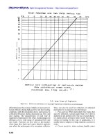
a) Example of a pipe connection using a rebated un-grooved spigot and flush coupling
b) Example of a pipe connection using a rebated grooved spigot and flush coupling
Key
dOD external diameter (see 3.1)
di internal diameter (see 3.4)
dg external diameter of the rebated spigot or in the groove, if applicable (see 3.5)
DEC external diameter of the flush coupling (see 3.39), expressed in millimetres (mm)
LC length of coupling, expressed in millimetres (mm)
x1 rebated length, expressed in millimetres (mm)
x2 distance of the groove to spigot end, expressed in millimetres (mm)
e pipe wall thickness (see 3.3)
Tg thickness of the smallest section under the groove, expressed in millimetres (mm)
Figure 3 — Examples of a pipe connection
© ISO 2011 – All rights reserved 15
ISO 25780:2011(E)
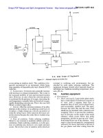
Table 2 — Maximum allowable installed deflection of pipe joints
External diameter Maximum allowable Maximum allowable
installed deflection installed deflection
dOD
mm a δ
dOD ≤ 200 mm/m degrees
200 < dOD ≤ 500 1,145 8
500 < dOD ≤ 1 000 20 0,859 4
0,572 9
1 000 < dOD 15
10 Derive from value of a
a = 10 × 1 000
d OD
Dimensions in metres
Key
δ Maximum angular deflection () in degrees (°).
a Maximum angular deflection in millimetres per metre (mm/m).
Figure 4 — Joint deflection
4.7.4 Sealing ring
The sealing ring shall not have any detrimental effect on the properties of the components with which it is
used and shall not cause the test assembly to fail the performance requirements specified in Clause 7 of this
International Standard.
4.7.5 Effect on water quality
When the pipes are intended to be used for the conveyance of water intended for human consumption,
attention is drawn to the need for components to comply with any national regulations on the quality of
drinking water in force at the location where the components are to be used.
5 Pipes
5.1 Geometrical characteristics
5.1.1 Jacking diameter
Pipes conforming with this International Standard have their diameter classified by their manufacturer's
declared pipe outside diameter, dOD (see 3.1). Because the outside diameter of a jacking pipe needs to be
compatible with the jacking machinery, the actual outside diameter of a pipe conforming to this International
Standard shall be agreed between the purchaser and the manufacturer.
16 © ISO 2011 – All rights reserved