ISO 260212:2008 Road vehicles — Endoflife activation of onboard pyrotechnic devices — Part 2: Communication requirements
Bạn đang xem bản rút gọn của tài liệu. Xem và tải ngay bản đầy đủ của tài liệu tại đây (1.42 MB, 56 trang )
INTERNATIONAL ISO
STANDARD 26021-2
First edition
2008-07-15
Road vehicles — End-of-life activation of
on-board pyrotechnic devices —
Part 2:
Communication requirements
Véhicules routiers — Activation de fin de vie des dispositifs
pyrotechniques embarqués —
Partie 2: Exigences de communication
Reference number
ISO 26021-2:2008(E)
© ISO 2008
ISO 26021-2:2008(E)
PDF disclaimer
This PDF file may contain embedded typefaces. In accordance with Adobe's licensing policy, this file may be printed or viewed but
shall not be edited unless the typefaces which are embedded are licensed to and installed on the computer performing the editing. In
downloading this file, parties accept therein the responsibility of not infringing Adobe's licensing policy. The ISO Central Secretariat
accepts no liability in this area.
Adobe is a trademark of Adobe Systems Incorporated.
Details of the software products used to create this PDF file can be found in the General Info relative to the file; the PDF-creation
parameters were optimized for printing. Every care has been taken to ensure that the file is suitable for use by ISO member bodies. In
the unlikely event that a problem relating to it is found, please inform the Central Secretariat at the address given below.
COPYRIGHT PROTECTED DOCUMENT
© ISO 2008
All rights reserved. Unless otherwise specified, no part of this publication may be reproduced or utilized in any form or by any means,
electronic or mechanical, including photocopying and microfilm, without permission in writing from either ISO at the address below or
ISO's member body in the country of the requester.
ISO copyright office
Case postale 56 • CH-1211 Geneva 20
Tel. + 41 22 749 01 11
Fax + 41 22 749 09 47
Web www.iso.org
Published in Switzerland
ii © ISO 2008 – All rights reserved
ISO 26021-2:2008(E)
Contents Page
Foreword............................................................................................................................................................ iv
Introduction ........................................................................................................................................................ v
1 Scope ..................................................................................................................................................... 1
2 Normative references ........................................................................................................................... 1
3 Terms and definitions........................................................................................................................... 2
4 Symbols and abbreviated terms ......................................................................................................... 2
5 Conventions .......................................................................................................................................... 3
6 Pyrotechnic device deployment via on-board diagnostic architecture .......................................... 3
6.1 Vehicle system description ................................................................................................................. 3
6.2 Example of in-vehicle hardware and software required ................................................................... 4
6.3 Additional communication line (optional) .......................................................................................... 5
6.4 Requirements for the PDT ................................................................................................................... 5
7 Relationship to existing standards ..................................................................................................... 6
7.1 General................................................................................................................................................... 6
7.2 Application layer ................................................................................................................................... 6
7.3 Session layer......................................................................................................................................... 6
7.4 Application layer and diagnostic session management timing....................................................... 6
7.5 Network layer ........................................................................................................................................ 7
7.6 Data link layer........................................................................................................................................ 7
7.7 Data link layer........................................................................................................................................ 9
7.8 Physical layer ........................................................................................................................................ 9
8 Deployment process............................................................................................................................. 9
8.1 General information.............................................................................................................................. 9
8.2 System preconditions .......................................................................................................................... 9
8.3 Initiation of the communication between PDT and PCU................................................................. 10
8.4 Deployment process description ...................................................................................................... 11
8.5 Software provisions............................................................................................................................ 19
8.6 Error handling and reaction............................................................................................................... 20
9 Communication with diagnostic services ........................................................................................ 21
9.1 Unified diagnostic services overview............................................................................................... 21
9.2 Diagnostic session control (10 hex) service.................................................................................... 21
9.3 EcuReset (11 hex) service ................................................................................................................. 22
9.4 Read data by identifier (22 hex) service ........................................................................................... 22
9.5 Write data by identifier (2E hex) service .......................................................................................... 29
9.6 Security access (27 hex) service....................................................................................................... 30
9.7 RoutineControl (31 hex) service........................................................................................................ 31
9.8 TesterPresent (3E hex) service ......................................................................................................... 35
Annex A (normative) Specification of the data identifier used.................................................................... 36
Annex B (normative) Deployment loop parameter definitions .................................................................... 41
Annex C (normative) Routine control parameter definitions....................................................................... 47
Bibliography ..................................................................................................................................................... 49
© ISO 2008 – All rights reserved iii
ISO 26021-2:2008(E)
Foreword
ISO (the International Organization for Standardization) is a worldwide federation of national standards bodies
(ISO member bodies). The work of preparing International Standards is normally carried out through ISO
technical committees. Each member body interested in a subject for which a technical committee has been
established has the right to be represented on that committee. International organizations, governmental and
non-governmental, in liaison with ISO, also take part in the work. ISO collaborates closely with the
International Electrotechnical Commission (IEC) on all matters of electrotechnical standardization.
International Standards are drafted in accordance with the rules given in the ISO/IEC Directives, Part 2.
The main task of technical committees is to prepare International Standards. Draft International Standards
adopted by the technical committees are circulated to the member bodies for voting. Publication as an
International Standard requires approval by at least 75 % of the member bodies casting a vote.
Attention is drawn to the possibility that some of the elements of this document may be the subject of patent
rights. ISO shall not be held responsible for identifying any or all such patent rights.
ISO 26021-2 was prepared by Technical Committee ISO/TC 22, Road vehicles, Subcommittee SC 3,
Electrical and electronic equipment.
ISO 26021 consists of the following parts, under the general title Road vehicles — End-of-life activation of
on-board pyrotechnic devices:
⎯ Part 1: General information and use case definitions
⎯ Part 2: Communication requirements
⎯ Part 3: Tool requirements
⎯ Part 4: Additional communication line with bidirectional communication
⎯ Part 5: Additional communication line with pulse width modulated signal
NOTE Additional parts will be introduced as necessary to take into account requirements not yet covered by the
standard.
iv © ISO 2008 – All rights reserved
ISO 26021-2:2008(E)
Introduction
ISO 26021 describes a method for the in-vehicle deployment of pyrotechnically activated components (also
referred to as pyrotechnic components or pyrotechnic devices) in cars.
Worldwide, nearly all new vehicles are equipped with one or more safety systems. Advanced protection
systems using pyrotechnic actuators are becoming more common. All components which contain pyrotechnic
substances should be handled in the same way.
Recycling of these vehicles requires a new process which ensures that the deactivation of airbags will be safe
and cost-efficient. Based on the harmonization of the on-board diagnostics (OBD) interface, there is an
opportunity to use this interface for on-board deployment, utilizing the same tools and processes.
The representatives of the global automobile industry have decided the following:
⎯ automobile manufacturers do not support reuse as an appropriate treatment method for pyrotechnic
devices;
⎯ automobile manufacturers believe treatment of pyrotechnic devices is required before shredding;
⎯ automobile manufacturers support in-vehicle deployment as the preferred method.
Based on this decision, the four major automobile manufacturer associations (ACEA, Alliance, JAMA and
KAMA) started to develop a method for the in-vehicle deployment of pyrotechnic components in cars with the
pyrotechnic device deployment tool (PDT). The vision is that, one day, a dismantler will need only one tool
without any accessories in order to deploy all the pyrotechnic devices inside an end-of-life vehicle (ELV). The
target is to use an existing interface to the car.
This part of ISO 26021 is applicable to the in-vehicle deployment of pyrotechnic devices in vehicles. It defines
communication methods to be implemented by a pyrotechnic control unit (PCU) to allow the PDT to
successfully establish and maintain communication with the PCUs in the vehicle to deploy all of the
pyrotechnic devices sequentially.
© ISO 2008 – All rights reserved v
INTERNATIONAL STANDARD ISO 26021-2:2008(E)
Road vehicles — End-of-life activation of on-board pyrotechnic
devices —
Part 2:
Communication requirements
1 Scope
This part of ISO 26021 defines the deployment process, the system architecture, CAN-based communication
methods and system preconditions which have to be implemented to fulfil the use cases defined in
ISO 26021-1. Additionally, the relationship to and use with other existing standards are defined.
This part of ISO 26021 also describes the technical details of the on-board deployment method. The way in
which the pyrotechnic devices contained in the vehicle function in conjunction with the PDT is the primary
focus of this document. Under the provisions of this document, the design of the PDT or PCU can be
implemented in accordance with specific functionality and hardware requirements.
This part of ISO 26021 specifies the access to the PCU. This includes communication as well as the logic
sequences which are involved during the activation process.
2 Normative references
The following referenced documents are indispensable for the application of this document. For dated
references, only the edition cited applies. For undated references, the latest edition of the referenced
document (including any amendments) applies.
ISO/IEC 10731, Information technology — Open Systems Interconnection — Basic Reference Model —
Conventions for the definition of OSI services
ISO 11898-1, Road vehicles — Controller area network (CAN) — Part 1: Data link layer and physical
signalling
ISO 14229-1, Road vehicles — Unified diagnostic services (UDS) — Part 1: Specification and requirements
ISO 15031-3, Road vehicles — Communication between vehicle and external equipment for emissions-related
diagnostics — Part 3: Diagnostic connector and related electrical circuits, specification and use
ISO 15765-2:2004, Road vehicles — Diagnostics on Controller Area Networks (CAN) — Part 2: Network layer
services
ISO 15765-3:2004, Road vehicles — Diagnostics on Controller Area Networks (CAN) — Part 3:
Implementation of unified diagnostic services (UDS on CAN)
ISO 15765-4, Road vehicles — Diagnostics on Controller Area Networks (CAN) — Part 4: Requirements for
emissions-related systems
ISO 26021-1, Road vehicles — End-of-life activation of on-board pyrotechnic devices — Part 1: General
information and use case definitions
ISO 26021-4, Road vehicles — End-of-life activation of on-board pyrotechnic devices — Part 4: Additional
communication line with bidirectional communication
© ISO 2008 – All rights reserved 1
ISO 26021-2:2008(E)
ISO 26021-5, Road vehicles — End-of-life activation of on-board pyrotechnic devices — Part 5: Additional
communication line with pulse width modulated signal
3 Terms and definitions
For the purposes of this document, the terms and definitions given in ISO 14229-1 and the following apply.
3.1
key
data value sent from the external test equipment to the on-board controller in response to the seed in order to
gain access to the locked services
3.2
pyrotechnic device deployment tool
tool designed to be plugged into the OBD interface in order to communicate via the internal computer network
in an end-of-life vehicle with all control units which are able to activate pyrotechnic devices
NOTE This tool will comprise e.g. a computer, a connection between the computer and the diagnostic connector, and
some software.
3.3
pyrotechnic control unit
PCU
electronic control unit in the vehicle network which controls the activation of pyrotechnic devices
3.4
safing
mechanism whose primary purpose is to prevent an unintended functioning of the PCU processor prior to
detection of a crash situation
3.5
safing unit
part of the PCU (e.g. an electromechanically operated switch or a separate processor) that allows the
pyrotechnic component deployment microprocessor (µP) to deploy the pyrotechnic devices via the driver
stage
3.6
scrapping program module
module responsible for firing the selected pyrotechnic device loops one by one
3.7
scrapping program module loader
module responsible for converting the scrapping program module to an executable format
3.8
seed
pseudo-random data value sent from the on-board controller to the external test equipment, which is
processed by the security algorithm to produce the key
4 Symbols and abbreviated terms
ACL additional communication line
CAN controller area network
ELV end-of-life vehicle
OBD on-board diagnostics
2 © ISO 2008 – All rights reserved
ISO 26021-2:2008(E)
PCU pyrotechnic control unit
PDT pyrotechnic device deployment tool
RAM random access memory
SPL scrapping program module loader
SPM scrapping program module
SRS supplementary restraint system
µC microcontroller
5 Conventions
ISO 26021 is based on the conventions for the definition of OSI services (see ISO/IEC 10731) as they apply to
diagnostic services.
6 Pyrotechnic device deployment via on-board diagnostic architecture
6.1 Vehicle system description
ISO 26021 is based on a vision of the diagnostic network architecture in combination with the PCU
deployment architecture that is described below.
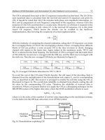
The PCU is connected to the vehicle diagnostic connector in accordance with ISO 15031-3. The PDT
communicates with the PCU on CAN_H and CAN_L, which are the mandatory vehicle interfaces.
Depending upon the specific architecture of the vehicle, the mandatory link of the PCU may be connected via
a gateway to the diagnostic connector; thus a CAN interface in the PCU for the mandatory link may not be
required.
During the deployment procedure, the vehicle PCUs shall be powered by the vehicle battery or, if the battery
is flat, by connecting an external power source to the battery terminals.
This requires an undamaged electrical architecture for the devices involved.
Figure 1 — Access to the vehicle via diagnostic connector
© ISO 2008 – All rights reserved 3
ISO 26021-2:2008(E)
To interface the PCU with the vehicle, a PDT to diagnostic connector interface shall be used. The purpose of
this interface is to
⎯ provide the CAN bus interface and optional ACL interface with the vehicle;
⎯ provide widely known standard wire interfaces like UART (RS232) or USB, or wireless interfaces like
BLUETOOTH and WLAN.
The PDT could be based on a PC architecture running the operation system and application software from a
bootable compact disc (CD) to avoid independence from software of any operating system, or the PDT could
consist of a separate operating console.
6.2 Example of in-vehicle hardware and software required
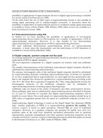
To execute the on-board deployment via the communication link, the software inside the PCU shall have full
access to the output driver stage, which controls the deployment loops.
In the solution without an ACL, a mechanical acceleration switch in the deployment loop circuit would not be
able to carry out the redundant safing function.
To achieve a reasonable functionality without the classical safing design, an independent electronic safing unit
is recommended due to the different safing philosophies of the various vehicle manufacturers. This unit could
receive the required safing acceleration data from a second acceleration sensor inside the PCU or from an
external frontal sensor.
Thus the deployment loop output stage is controlled by two independent branches. Depending on the safing
philosophy of the vehicle manufacturer, the safing path could be controlled via the optional ACL or the main
deployment processor.
Figure 2 — Overview of hardware and software required
4 © ISO 2008 – All rights reserved
ISO 26021-2:2008(E)
6.3 Additional communication line (optional)
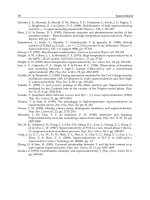
For special safety requirements, an additional signal can be applied. General requirements for the interface
between the deployment sequence and the ACL sequence are as shown in Figure 3.
Figure 3 — Integration of ACL communication into deployment process
The standardized steps specify the diagnostic sequence. This type of step is mandatory. The PDT and the
PCU shall behave as specified. The optional steps are necessary if the original equipment manufacturer
(OEM) chooses the additional communication line. Optional ACL steps will depend on the use of the ACL
option. Only while communicating with a PCU having an ACL is the PDT allowed to connect with the ACL line.
These steps are mandatory only for the optional ACL. These optional steps are detailed in ISO 26021-4 and
ISO 26021-5.
6.4 Requirements for the PDT
6.4.1 Power supply
This subclause defines the requirements for the PDT to be able to establish communication with the PCUs
and successfully activate the pyrotechnic devices installed in the vehicle.
The PCUs shall be powered internally so that they are independent of the power supply of the vehicle even if
pins 4 and 16 on the diagnostic connector provide a permanent power supply when the vehicle is powered.
This is to achieve robustness against a damaged power supply in the diagnostic connector. However, the tool
may provide the capability to recharge its internal batteries using pins 4 and 16 of the diagnostic connector if
the power supply on these pins has not been damaged.
6.4.2 Initial condition of vehicle
The operation can only start if full access to the vehicle is granted via a suitable identification method (e.g.
ignition key or keyless entry unit).
It is necessary to ensure that the vehicle's electronic system is active for communication via the diagnostic
connector.
6.4.3 Safety requirements
To execute the on-board deployment function via the diagnostic connection, a software module inside the
PCU is required which performs the necessary steps to control the output stages, overrides the safing unit
(alternative use of ACL) and carries out the communication to the PDT. To avoid any inadvertent deployment
© ISO 2008 – All rights reserved 5
ISO 26021-2:2008(E)
caused by the deployment software module in the PCU, it shall be stored in a non-executable format in the
program memory of the PCU and shall only be activated by an SPL which is an executable program code.
A key code from the PDT is required to enable the SPL to load the SPM into the RAM and convert the SPM to
an executable format.
After a further communication sequence of the PDT with the PCU, the SPM will communicate to the
independent electronic safing unit (if no ACL is available), activate the output stages and record this event
individually for each deployment loop.
When an ACL is present, the unlock signal on this line has to be present during the deployment event and
evaluated by the independent safing unit to release the output.
After the deployment sequence of this particular PCU is completed, the PDT may request a reset of the PCU
and the PCU exits the scrapping mode.
6.4.4 Suitability of vehicle
Vehicles that can be scrapped via the diagnostic connector will respond to the PDT. All others will not.
7 Relationship to existing standards
7.1 General
All clauses of ISO 11898-1, ISO 14229-1 and the relevant part of ISO 15765 are applicable for the PCU
deployment process, with the restrictions/additions defined below.
7.2 Application layer
This part of ISO 26021 uses the application layer services and protocol as defined in ISO 14229-1 for client-
server-based systems to perform functions such as initialization, monitoring or start of functions of on-board
vehicle servers like the PCU.
7.3 Session layer
For security reasons, the scrapping sequence shall take place in the deployment session.
7.4 Application layer and diagnostic session management timing
This part of ISO 26021 uses the application layer and session layer timing parameters as defined in
ISO 14229-1 and ISO 15765-3. The detailed timing parameter descriptions for physical communication and
functional communication shall be in accordance with ISO 15765-3. Although functional communication is not
necessary for this part of ISO 26021, ∆P2CAN shall be between 0 ms and 500 ms. The PDT needs to detect
P2CAN_Client timeout and this part of ISO 26021 specifies the ∆P2CAN value for gateway design.
In the case of a communication error, it is assumed that the client and the server implement the application
and session layer timing as defined in ISO 15765-3. The client (i.e. the PDT) shall repeat the last request a
maximum of two (2) times, which means that the greatest number of service request transmissions is three (3).
In the case of the worst-case communication error, the PDT shall stop the execution of the deployment
process.
6 © ISO 2008 – All rights reserved
ISO 26021-2:2008(E)
7.5 Network layer
The network layer of the external equipment (i.e. the PDT) and the vehicle, which may have one or more
PCUs, shall be compliant with the standard diagnostic specification in ISO 15765-4, with the restrictions
defined below:
⎯ the PDT shall not transmit the FC.WAIT frame in the segmented response message;
⎯ the PDT shall not transmit the FC frame with the non-zero block size (BS) parameter in the segmented
response message;
⎯ the PDT shall not transmit the FC frame with the non-zero separation time (STmin) parameter in the
segmented response message;
⎯ the maximum number of FC.Wait frame transmission (N_WFTmax) parameters shall be zero.
For the parameters used above, see ISO 15765-2:2004, Subclause 6.5.5, “FlowControl N_PCI parameter
definition”.
From the external test equipment (PDT) point of view, each PCU in a compliant vehicle must have an
addressed CAN identifier.
For the initialization sequence only, the normal addressing format and normal fixed addressing format as
defined in ISO 15765-2 shall be used.
⎯ 11 bit CAN identifiers: normal addressing;
⎯ 29 bit CAN identifiers: normal fixed addressing.
After the initialization sequence, the OEM-specific combinations can be used as defined in Table 3 to Table 5.
7.6 Data link layer
7.6.1 11 bit CAN identifiers
Table 1 specifies the 11 bit CAN identifiers for safety-relevant initialization aspects, based on the defined
mapping of the diagnostic addresses.
CAN identifier Table 1 — 11 bit safety-relevant identifiers
(hex) Description
7F1 Physical request CAN identifier from the external test equipment to PCU #1
Physical response CAN identifier from PCU #1 to the external test equipment PDT
7F9
© ISO 2008 – All rights reserved 7
ISO 26021-2:2008(E)
7.6.2 29 bit CAN identifiers
Table 2 specifies the 29 bit CAN identifiers for safety-relevant initialization aspects, based on the defined
mapping of the diagnostic addresses.
CAN identifier Table 2 — 29 bit PCU deployment CAN identifiers
(hex) Description
18 DA 53 F1 Physical request CAN identifier from the external test equipment to PCU 0x53 (hex)
Physical response CAN identifier from PCU 0x53 (hex) to the external test equipment
18 DA F1 53
The maximum number of safety-relevant ECUs in a PCU deployment compliant vehicle is not limited. The
physical PCU diagnostic address of the fixed-address PCU is “0x53” hex. This address, embedded in the
physical CAN identifiers, shall be unique to any one vehicle.
7.6.3 Mapping of network layer protocol data units to PCU address information of in-vehicle PCUs
The PCUAddressFormat byte defines the mapping of the request and response addresses into a 32 bit field
as defined in Tables 3 to 5.
Table 3 — Reserved PCU Address Format
8 bit field 32 bit field request/response address
PCUAddress
Byte 1 (MSB) Byte 2 Byte 3 Byte 4 (LSB)
Format
31 24 23 19 18 16 15 8 7 0
0x00
Reserved 0x07 … 0xFF 0x00, 0x00, 0x00, 0x00
Reserved
ISO/SAE reserved for future use
Table 4 — Mapping of 11 bit N_PDU parameters into the 32 bit request/response address
11 bit mapping 8 bit field 32 bit field request/response address
(e.g. CAN) PCUAddress See ISO 15765-2:2004, Subclause 7.3, Mapping of the N_PDU fields.
11 bit — normal Format Byte 1 (MSB) Byte 2 Byte 3 Byte 4 (LSB)
addressing
0x01 31 24 23 19 18 16 15 8 7 0
11 bit — extended 0x02
addressing 0x03 0x00 0b0000 0 N_AI 0xFF (default)
11 bit — mixed 0x00 0b0000 0 N_AI, except N_TA N_TA
addressing
0x00 0b0000 0 N_AI N_AE
8 © ISO 2008 – All rights reserved
ISO 26021-2:2008(E)
Table 5 — Mapping of 29 bit N_PDU parameters into the 32 bit request/response address
29 bit mapping 8 bit field 32 bit field request/response address
(e.g. CAN) PCUAddress
See ISO 15765-2:2004, Subclause 7.3, Mapping of the N_PDU fields, and
29 bit — normal Format ISO 15765-3:2004, Subclause 8.3, Enhanced diagnostics 29 bit CAN identifiers.
fixed addressing
29 bit — mixed 0x04 Byte 1 (MSB) Byte 2 Byte 3 Byte 4 (LSB)
0x05
addressing 0x00 N_TA N_SA 0xFF
ISO 15765-3 0x06
0x00 N_TA N_SA N_AE
mapping
Unique addressing 31 22 21 11 10 0
0b00 0110 1111 Unique source address Unique destination
address
7.7 Data link layer
There is no addition or restriction to the data link layer.
7.8 Physical layer
The PDT shall support all legislated OBD baud rates. If this is not possible, the PDT shall support at least the
baud rates of 250 kbit/s and 500 kbit/s.
8 Deployment process
8.1 General information
This clause defines the general steps in the deployment process. It starts with the interface requirements for
the external test equipment. This is followed by a description of the deployment sequence. See also Figure 4.
8.2 System preconditions
8.2.1 General
If the minimum requirements (see 6.4.2) are not fulfilled, the deployment session cannot be started. All enable
conditions shall be checked before the session is initiated.
If the PCU cannot determine whether the conditions are met (e.g. due to a system failure or because of the
design), it shall be assumed the conditions are fulfilled.
8.2.2 Notification enable condition
After adequate notification of the user, the system should awaken and the power to the PCUs should be
switched on.
If a signal “ignition key on” or other such information is available, these shall be checked.
8.2.3 Not in motion enable condition
If the information “vehicle is not in motion” is available, it shall be checked.
© ISO 2008 – All rights reserved 9
ISO 26021-2:2008(E)
8.3 Initiation of the communication between PDT and PCU
The purpose of the initiation sequence is to automatically detect if the vehicle supports standardized
communication on the CAN bus, with the physical layer defined in ISO 15765-4. All related messages using
this protocol shall use either a 250 kbit/s or a 500 kbit/s baud rate.
The PDT shall transmit a service ID 0x22 (Read Data By Identifier) with Data Identifier 0xFA00 “Number of
PCUs in Vehicle”, using the ISO 15765-2 transport protocol with “normal fixed addressing” on the predefined
Request-CAN-ID assigned to the fixed-address PCU. This service is a single-frame service.
The PDT cycles through the available protocols in the following sequence:
⎯ ISO 15765-4 — 11 bit identifier with physical normal addressing;
⎯ ISO 15765-4 — 29 bit identifier with physical normal fixed addressing.
Contrary to the CAN-identifiers defined in ISO 15765-4, the PDT shall use the following CAN-identifiers to
establish communication with the fixed-address PCU installed in the vehicle using the CAN-connection:
11 bit CAN-ID:
⎯ Request: 0x7F1 (fixed-address PCU)
⎯ Response: 0x7F9 (fixed-address PCU)
⎯ Data length code (DLC): 8
29 bit CAN-ID:
⎯ Request: 0x18DA53F1
⎯ Response: 0x18DAF153
⎯ Data length code (DLC): 8
NOTE There is no support of former OBD protocols (e.g. SAE J1850 41,6 kbit/s PWM, SAE J1850 10,4 kbit/s VPW,
ISO 9141-2, ISO 14230-4) or OEM-specific hooks.
10 © ISO 2008 – All rights reserved
ISO 26021-2:2008(E)
Figure 4 — CAN interface initialization sequence — Overview
8.4 Deployment process description
8.4.1 Deployment process — Overview
After the PDT has detected the PCU (connector C), the PDT shall carry out the following steps to perform the
deployment process.
If the optional ACL is used, there are three possible connections to the ACL process sequence. The PDT shall
manage these options at the defined steps. See Figure 5 for detailed information. Subclauses 8.4.2 to 8.4.6
contain a detailed description of the CAN communication sequence.
© ISO 2008 – All rights reserved 11
ISO 26021-2:2008(E)
Figure 5 (continued on next page)
12 © ISO 2008 – All rights reserved
ISO 26021-2:2008(E)
Key
1 The implementation of the PCU can differ from vehicle to vehicle. The Sys-Init part does the in-vehicle configuration.
First, the PDT ascertains the identification of the vehicle. Then, the PDT starts the documentation and stores the
dismantler information in the vehicle.
2 The PDT shall check whether the version of the method of deployment used by the first PCU is supported. If the
version is supported, the PDT shall proceed with connector D. If the PCU version required is higher than the PDT
version supported, the PDT shall end the process and update its software. Currently only version 0x01 is defined.
However, the PCU deployment method version allows for extending and adapting the standard for PCU deployment to
meet future demands.
3 The PDT selects the PCUs in the sequence based on the address information of the PCUs and carries out the
security handling. The PDT checks the conditions, authorizes the test and selects one PCU which will be referred to
as PCU(n). The PDT proceeds to connector E.
4 Currently, no additional ACL preparation in the CAN communication is necessary. The PDT shall proceed to
connector F if no ACL is selected. If the ACL option is selected, the PDT shall proceed to 10.
5 The PDT reads out from PCU(n) the status of the pyrotechnic devices connected to it. Then the PDT starts the device
scrapping session for this PCU(n).
6 If PCU(n) supports more than one pyrotechnic device, the PDT shall select the next device and proceed to
connector F. If the last pyrotechnic device has been selected, the PDT shall end the device loop and proceed to 7.
7 The PDT ends the session with PCU(n) and proceeds to 8.
8 If there is more than one PCU, the PDT shall select the next PCU and proceed to connector E. If the last PCU has
been selected, the PDT shall proceed to connector G.
9 The PDT writes the documentation to the PCU 1. The connector “End” terminates the sequence.
10 If the ACL is selected, the PDT can prepare ACL step 1 — request deployment sequence (see ISO 26021-4 or
ISO 26021-5 for a detailed description).
11 If the ACL is selected, the PDT can prepare ACL step 2 — deployment confirmation sequence. If necessary, the PDT
shall hold the ACL deployment process currently in progress (see ISO 26021-4 or ISO 26021-5 for a detailed
description).
12 If the ACL is selected, the PDT can prepare ACL step 3 — deployment termination sequence (see ISO 26021-4 or
ISO 26021-5 for a detailed description).
Figure 5 — Deployment process — Overview
8.4.2 Deployment process — Sys-Init
Most of today's vehicle designs have only one PCU. However, future designs could include more than one
PCU and the PCUs could be responsible for different numbers of pyrotechnic devices. For example, today the
fixed-address PCU is responsible for at least two PCU devices. The power module could be responsible for
the pyrotechnic device and the battery clamp. Nevertheless, the PDT has to distinguish between a simple
design with one PCU and a decentralized system with more than one PCU. The purpose of this subclause is
to detect automatically the in-vehicle configuration. See Figure 6 for a detailed description.
In the Sys-Init deployment process, the vehicle is requested to provide data on the specific configuration. The
PDT stores all of these data for use later in the sequence. The PCUs will be handled in exactly the sequence
in which they are stored in the fixed-address PCU.
To be compatible with special requirements and future changes, the PDT requests the parameter “PCU
deployment method” from the fixed-address PCU (see 9.4.4). The PDT determines from the result, “PCU
deployment method version”, the protocol implemented by all the PCUs in the vehicle concerned. Currently,
only version 0x01 is defined. However, the PCU deployment method version allows for extending and
adapting the standard to future demands.
The parameter “ACL type” of the data identifier “deployment method version” determines the hardware design
version implemented in the vehicle. If the parameter “ACL type” is set to “additional communication line is
used”, the optional ACL steps are selected. If no ACL is supported, the ACL line shall be assumed to be high
impedance for safety reasons. See ISO 26021-4 and the following for detailed specifications.
The PCU/PDT shall use the additional communication line type definitions specified in Table A.6 of this part of
ISO 26021 (Data Identifier 0xFA06; Data Byte 1) in accordance with the descriptions in Table 6.
© ISO 2008 – All rights reserved 13
ISO 26021-2:2008(E)
Table 6 — PCU/PDT description
Scaling ACL type definition Description
0x01 CAN only Additional communication line is not used.
0x02 ACL_CommMode_12V Additional communication line with bidirectional communication in accordance
with ISO 26021-4 is used; vehicle battery voltage is 12 V.
0x03 ACL_PWM_FixedLevel_8V Additional communication line with pulse width modulated signal in accordance
with ISO 26021-5 is used (high level of signal is derived from a fixed voltage of
8 V which has to be provided by the DTT/PDT).
0x04 ACL_CommMode_24V Additional communication line with bidirectional communication in accordance
with ISO 26021-4 is used; vehicle battery voltage is 24 V.
0x05 ACL_PWM_UbattLevel_12V Additional communication line with pulse width modulated signal is used.
Signal timing is compliant with ISO 26021-5.
Signal voltage level is compliant with ISO 26021-4 (high level of signal is
derived from vehicle battery voltage which is provided via pin 16 of the
diagnostic connector).
0x06 Vehicle battery voltage is 12 V.
ACL_PWM_UBattLevel_24V Additional communication line with pulse width modulated signal is used.
Signal timing is compliant with ISO 26021-5.
Signal voltage level is compliant with ISO 26021-4 (high level of signal is
derived from vehicle battery voltage which is provided via pin 16 of the
diagnostic connector).
Vehicle battery voltage is 24 V.
14 © ISO 2008 – All rights reserved