ISO 29081:2010 Surface chemical analysis — Auger electron spectroscopy — Reporting of methods used for charge control and charge correction
Bạn đang xem bản rút gọn của tài liệu. Xem và tải ngay bản đầy đủ của tài liệu tại đây (960.34 KB, 30 trang )
INTERNATIONAL ISO
STANDARD 29081
First edition
2010-02-15
Surface chemical analysis — Auger
electron spectroscopy — Reporting of
methods used for charge control and
charge correction
Analyse chimique des surfaces — Spectroscopie des électrons
Auger — Indication des méthodes mises en œuvre pour le contrôle et la
correction de la charge
Reference number
ISO 29081:2010(E)
© ISO 2010
ISO 29081:2010(E)
PDF disclaimer
This PDF file may contain embedded typefaces. In accordance with Adobe's licensing policy, this file may be printed or viewed but
shall not be edited unless the typefaces which are embedded are licensed to and installed on the computer performing the editing. In
downloading this file, parties accept therein the responsibility of not infringing Adobe's licensing policy. The ISO Central Secretariat
accepts no liability in this area.
Adobe is a trademark of Adobe Systems Incorporated.
Details of the software products used to create this PDF file can be found in the General Info relative to the file; the PDF-creation
parameters were optimized for printing. Every care has been taken to ensure that the file is suitable for use by ISO member bodies. In
the unlikely event that a problem relating to it is found, please inform the Central Secretariat at the address given below.
COPYRIGHT PROTECTED DOCUMENT
© ISO 2010
All rights reserved. Unless otherwise specified, no part of this publication may be reproduced or utilized in any form or by any means,
electronic or mechanical, including photocopying and microfilm, without permission in writing from either ISO at the address below or
ISO's member body in the country of the requester.
ISO copyright office
Case postale 56 • CH-1211 Geneva 20
Tel. + 41 22 749 01 11
Fax + 41 22 749 09 47
Web www.iso.org
Published in Switzerland
ii © ISO 2010 – All rights reserved
ISO 29081:2010(E)
Contents Page
Foreword ............................................................................................................................................................iv
Introduction ......................................................................................................................................................... v
1 Scope ......................................................................................................................................................1
2 Normative references............................................................................................................................1
3 Terms and definitions ...........................................................................................................................1
4 Symbols and abbreviated terms ..........................................................................................................1
5 Apparatus ...............................................................................................................................................2
5.1 Charge-control technique.....................................................................................................................2
5.2 Special apparatus..................................................................................................................................2
5.3 Specimen mounting and preparation..................................................................................................3
5.4 Instrument calibration...........................................................................................................................3
6 Reporting of information related to charge control ...........................................................................3
6.1 Methods of charge control ...................................................................................................................3
6.2 Reasons for needing charge control and choice of method ............................................................3
6.3 Specimen information...........................................................................................................................3
6.3.1 Specimen form.......................................................................................................................................3
6.3.2 Specimen dimensions...........................................................................................................................4
6.3.3 Specimen-mounting methods ..............................................................................................................4
6.3.4 Specimen treatment prior to or during analysis ................................................................................4
6.4 Values of experimental parameters.....................................................................................................4
6.5 Information on the effectiveness of methods of charge control ......................................................4
7 Reporting of method(s) used for charge correction and the value of that correction ...................5
7.1 Methods of charge correction..............................................................................................................5
7.2 Approach ................................................................................................................................................5
7.3 Value of correction energy ...................................................................................................................5
Annex A (informative) Description of methods of charge control for Auger electron spectroscopy ........6
A.1 Introduction ............................................................................................................................................ 6
A.2 Hierarchical table of methods for reducing charging........................................................................7
A.3 Methods for minimizing charging during AES ...................................................................................9
A.3.1 Introduction ............................................................................................................................................ 9
A.3.2 Decreasing specimen resistivity..........................................................................................................9
A.3.3 Decreasing the insulator thickness (or effective insulator thickness) ............................................9
A.3.4 Reducing the current density, limiting primary-electron dose and using additional current
sources .................................................................................................................................................11
A.3.5 Optimizing the total secondary-electron emission yield.................................................................12
A.4 Considerations for highly non-uniform specimens, fibres and particles and the use of
sputter depth profiling ........................................................................................................................14
A.4.1 Introduction .......................................................................................................................................... 14
A.4.2 Dealing with rough surfaces, particles, fibres and other non-uniform specimens ......................14
A.4.3 Sputter depth profiling........................................................................................................................14
A.5 General considerations concerning charge build-up during AES .................................................15
A.5.1 Introduction .......................................................................................................................................... 15
A.5.2 Resistivity, capacitance and surface potential ................................................................................15
A.5.3 Total secondary-electron yield and surface potential .....................................................................17
A.5.4 Charge transport and accumulation below the surface, time-dependent charge
accumulation and specimen damage................................................................................................20
Bibliography ...................................................................................................................................................... 21
© ISO 2010 – All rights reserved iii
ISO 29081:2010(E)
Foreword
ISO (the International Organization for Standardization) is a worldwide federation of national standards bodies
(ISO member bodies). The work of preparing International Standards is normally carried out through ISO
technical committees. Each member body interested in a subject for which a technical committee has been
established has the right to be represented on that committee. International organizations, governmental and
non-governmental, in liaison with ISO, also take part in the work. ISO collaborates closely with the
International Electrotechnical Commission (IEC) on all matters of electrotechnical standardization.
International Standards are drafted in accordance with the rules given in the ISO/IEC Directives, Part 2.
The main task of technical committees is to prepare International Standards. Draft International Standards
adopted by the technical committees are circulated to the member bodies for voting. Publication as an
International Standard requires approval by at least 75 % of the member bodies casting a vote.
Attention is drawn to the possibility that some of the elements of this document may be the subject of patent
rights. ISO shall not be held responsible for identifying any or all such patent rights.
ISO 29081 was prepared by Technical Committee ISO/TC 201, Surface chemical analysis, Subcommittee
SC 5, Auger electron spectroscopy.
iv © ISO 2010 – All rights reserved
ISO 29081:2010(E)
Introduction
Auger electron spectroscopy (AES) is widely used for characterization of surfaces of materials. Elements in
the sample (with the exception of hydrogen and helium) are identified from comparisons of Auger transition
energies, determined from measured Auger spectra, with tabulations of these energies for the various
elements. Although Auger electrons are observed during X-ray irradiation of specimens (X-ray photoelectron
spectroscopy), AES, as used in this document, is associated with electron irradiation of a specimen. Because
the incident electron beam can be focused to sizes approximating 10 nm, AES is an important tool for
characterization of small surface features and of nanostructured materials. Information on the elements
present, and sometimes the chemical state of the detected elements, can frequently be obtained from
examination of the line shape and energies of the peaks (see ISO/TR 18394[43]). Reliable determination of
elements present requires appropriate calibration of the energy scale (as described in ISO 17973 and
ISO 17974).
The surface potential of an insulating specimen may change during an AES measurement due to the build-up
of surface and near-surface electrical charge, and this charge can shift the energy of Auger electrons, thus
complicating elemental (and chemical state) identification, especially when a negative surface potential moves
the Auger spectrum above the energy interval selected by the electron analyser. The build-up of surface
potential can also move the location of the electron beam, effectively shifting the region on the specimen or
even off the specimen that is being analysed. Similar changes occur for metals during electron irradiation if
they are not connected to ground. This would occur, for example, if small metal particles are incorporated in
an insulating matrix. Depending on the secondary-electron yield, the surface potential may shift positively or
negatively. In some circumstances, these two shifts (energy and position) create an unstable feedback system,
rendering the collection of AES spectra nearly impossible. In addition to changes in the Auger-electron peak
energy and intensity, the specimen surface composition might be altered (specimen damage) directly by the
incident electron beam or due to electric-field-induced diffusion when a field is set up in the surface region of
the specimen. A variety of methods and approaches have been developed to control and minimize charging
effects in AES. The application of a particular method can be highly dependent on the details of the instrument
being used, the size and shape of the specimen being examined, the specimen morphology and composition,
and the information to be collected. Although the build-up of surface charge can complicate analysis, in some
circumstances it can also be used creatively as a tool to gain information about the specimen.
The amount of induced charge near the surface, its distribution across the specimen surface, and its
dependence on experimental conditions are determined by many factors, including those associated with the
specimen and the characteristics of the spectrometer. Charge build-up is a well-studied[1] three-dimensional
phenomenon that occurs along the specimen surface and into the material. Charge build-up may also occur at
phase boundaries or interface regions within the depth of a specimen that is irradiated by electrons. Some
specimens undergo time-dependent changes in charge build-up due to charge trapping, chemical changes or
component diffusion or volatilization induced by heating or by incident or secondary electrons. Such
specimens may never achieve steady-state potentials.
There is, at present, no universally applicable method or set of methods for charge control or for charge
correction in AES[2],[3]. This International Standard specifies the information that has to be provided to
document the method of charge control during data acquisition and/or the method of charge correction during
data analysis of insulating specimens. Information is given in Annex A on common methods for charge control
that can be useful for many applications. The particular charge-control method that may be chosen in practice
depends on the type of specimen (e.g. powder, thin film or thick specimen), the nature of the instrumentation,
the size of the specimen and the extent to which the specimen surface might be modified by a particular
procedure. To assist an analyst, a summary table lists the common charge-control methods in approximate
order of simplicity of application.
This International Standard has two main areas of application. First, it identifies information on methods of
charge control and/or charge correction to be included in reports of AES measurements (e.g. from an analyst
to a customer or in publications) in order to evaluate and reproduce data on insulating materials and to ensure
that measurements on similar materials can be meaningfully compared. Second, adherence to the
International Standard will enable published AES spectra to be used with confidence by other analysts.
© ISO 2010 – All rights reserved v
INTERNATIONAL STANDARD ISO 29081:2010(E)
Surface chemical analysis — Auger electron spectroscopy —
Reporting of methods used for charge control and charge
correction
1 Scope
This International Standard specifies the minimum amount of information required for describing the methods
of charge control in measurements of Auger electron transitions from insulating specimens by electron-
stimulated Auger electron spectroscopy and to be reported with the analytical results. Information is provided
in Annex A on methods that have been found useful for charge control prior to or during AES analysis. This
annex also contains a table summarizing the methods or approaches, ordered by simplicity of approach.
Some methods will be applicable to most instruments, others require special hardware, others might involve
remounting the specimen or changing it. A similar International Standard has been published for X-ray
photoelectron spectroscopy (ISO 19318[44]).
2 Normative references
The following referenced documents are indispensable for the application of this document. For dated
references, only the edition cited applies. For undated references, the latest edition of the referenced
document (including any amendments) applies.
ISO 17973, Surface chemical analysis — Medium-resolution Auger electron spectrometers — Calibration of
energy scales for elemental analysis
ISO 17974, Surface chemical analysis — High-resolution Auger electron spectrometers — Calibration of
energy scales for elemental and chemical-state analysis
ISO 18115, Surface chemical analysis — Vocabulary
3 Terms and definitions
For the purposes of this document, the terms and definitions given in ISO 18115 apply.
4 Symbols and abbreviated terms
AES Auger electron spectroscopy
Ep primary-electron energy, in keV
Ep(max) energy at which the TSEEY is a maximum
E0p1 energy at which the secondary-electron emission yield rises above unity
E0p2 energy at which the secondary-electron emission yield drops below unity
© ISO 2010 – All rights reserved 1
ISO 29081:2010(E)
Ecp2 energy at which the range of the incident electrons is approximately equal to the maximum escape
depth of the secondary electrons
FIB focused ion beam
FWHM full width at half maximum, in eV
Ip primary-electron current
Is secondary-electron current
jp current density of the primary-electron beam on the specimen surface
KEcorr corrected kinetic energy, in eV
KEmeas measured kinetic energy, in eV
KEref reference kinetic energy, in eV
N charging index
R range of primary electrons
SEM scanning electron microscopy
t electron irradiation time
TSEEY total secondary-electron emission yield
Us surface potential
Ve electron interaction volume
z specimen thickness
ρ electrical resistivity of the specimen
σ total secondary-electron yield
θ angle of incidence of primary-electron beam on the specimen with respect to the surface normal, in
degrees
∆corr correction energy, to be added to measured Auger electron energies for charge correction, in eV
5 Apparatus
5.1 Charge-control technique
One or more of the charge-control techniques described in Clause A.3 may be employed in most AES
spectrometers. The AES instrument shall be operated in accordance with the manufacturer's or other
documented procedures.
5.2 Special apparatus
Some of the techniques outlined in Clause A.3 require special apparatus, such as a low-energy ion source or
a source for evaporative deposition of gold. Some of the referenced items may be the subject of patent rights
for specific vendors. Mention of them here is for convenience and does not represent an endorsement by ISO
or a member body.
2 © ISO 2010 – All rights reserved
ISO 29081:2010(E)
5.3 Specimen mounting and preparation
Certain specimen-mounting procedures, such as mounting the specimen under a fine metal mesh[3],[4], can
enhance electrical contact of the specimen with the specimen holder or reduce the amount of surface charge
build-up. This and other methods of specimen mounting to reduce static charge are described in detail in
ISO 18116[5] and ISO 18117[42] (and in ASTM E1078[4] and ASTM E1829[6].
5.4 Instrument calibration
The kinetic-energy scale of the Auger electron spectrometer shall be calibrated using ISO 17973 or
ISO 17974 or another documented method before using this International Standard.
6 Reporting of information related to charge control
6.1 Methods of charge control
Many of the methods commonly used to control the surface potential and to minimize surface charging are
described in Clause A.3. Information on reasons for charge control, choice of a charge-control method, and
critical specimen and experimental conditions, as described in 6.2, 6.3 and 6.4, shall be reported (or
referenced) for individual specimens or collections of similar specimens.
6.2 Reasons for needing charge control and choice of method
The reasons for needing charge control and for choosing a particular method shall be reported.
EXAMPLE 1 The specimen was an insulating film deposited on a conducting substrate. By using an electron primary-
beam energy above 10 keV, no specimen charging was observed.
EXAMPLE 2 Experience with similar specimens indicated that charging was likely. To minimize charging, the
specimens were mounted under a conducting aperture and beam energies below 3 keV were used. The current was
adjusted until the AES spectra obtained were reproducible and stable.
EXAMPLE 3 Spectra recorded initially without any charge control showed peak shifting and broadening. Placing a
grounded fine-mesh grid above the specimen minimized these problems. Repeated analyses showed that changes in
specimen composition due to charge build-up were below 10 % if the total electron dose was below 1 000 C/m2.
If the components used for charge control are not standard for the AES instrument, information on the
manufacturer or on the relevant design characteristics shall be provided or referenced.
NOTE A specimen does not need to be a good conductor for routine AES analysis to be accomplished without
charging problems. Although it is important to be aware of potential charging issues, experimental verification that they are
present is useful before great effort is spent minimizing possible difficulties.
6.3 Specimen information
6.3.1 Specimen form
The form of the specimen shall be reported. The physical nature, source, preparation method and structure of
a specimen can influence its charging behaviour[1],[2],[3].
EXAMPLE 1 Powder.
EXAMPLE 2 Thin film spin-cast on silicon.
EXAMPLE 3 Macroscopic mineral specimen.
© ISO 2010 – All rights reserved 3
ISO 29081:2010(E)
6.3.2 Specimen dimensions
The size, shape and surface roughness of a specimen can have a significant effect on the extent of specimen
charging. The shape of the specimen shall be reported, together with approximate values of the dimensions of
the specimen or of any relevant specimen features (e.g. particle diameters, surface roughness).
6.3.3 Specimen-mounting methods
Specimen mounting and contact with the specimen holder can significantly impact charging[1]. The method by
which a specimen is mounted, including information about special methods used to increase conductivity or
isolate a specimen from ground, shall be reported.
EXAMPLE 1 Powder specimen pressed into foil, which was attached to the specimen holder by conducting tape.
EXAMPLE 2 1 ml of solution containing nanoparticles was deposited on a silicon substrate and dried prior to analysis.
EXAMPLE 3 Specimen held to holder using conductive adhesive tape (with manufacturer and type of tape specified).
EXAMPLE 4 Corroded specimen held on specimen holder by metal screw.
EXAMPLE 5 Mineral specimen and conducting aperture mounted using metal screw.
EXAMPLE 6 Specimen mounted with the primary-electron beam at glancing incidence on the specimen surface.
6.3.4 Specimen treatment prior to or during analysis
Any specimen treatment prior to or during analysis, including any physical or chemical treatment that could
affect charging of the specimen during AES measurements, shall be reported.
NOTE Such treatment of the specimen can modify the surface composition as well as the electrical conductivity, and
hence charging, of the surface region.
6.4 Values of experimental parameters
Values of parameters used for AES measurements and charge control, including beam parameters (energy,
nominal incident current, beam size, raster area on the specimen, angle of incidence on the specimen),
irradiation time of the specimen during set-up and AES measurements, and operating parameters of ancillary
components such as a low-energy ion gun shall be recorded (or referenced).
EXAMPLE A focused electron beam with energy of 10 keV and 1 nA current at 45° incidence to the specimen
normal, rastered over an area of 200 nm by 200 nm, was used for the analysis.
6.5 Information on the effectiveness of methods of charge control
The adequacy of the charge-control method(s) used for the type of analysis being conducted shall be
established. Auger line peak positions (or peak widths) with and without a method of charge control provide
one way of determining the adequacy of the charge-control method. In some cases, the ability to determine
that the AES lines are within 5 eV of the expected value and that the relative peak amplitudes are stable might
be satisfactory.
EXAMPLE 1 The AES peak positions were within 5 eV of the nominal values and the peak shapes were both similar to
reference data and stable on repeated scans.
EXAMPLE 2 Repeated measurements in new areas demonstrated consistent agreement regarding peak shape and
relative intensity.
It is recommended that specimens be examined for the presence or absence of specimen damage and that
the results be recorded.
4 © ISO 2010 – All rights reserved
ISO 29081:2010(E)
7 Reporting of method(s) used for charge correction and the value of that
correction
7.1 Methods of charge correction
In many cases, the methods used to control charge eliminate the need for further correction of the Auger peak
energies. If a method of charge correction is applied to AES data, the following critical specimen and
experimental parameters shall be reported.
7.2 Approach
Any method for correcting the measured kinetic energy of the Auger peaks for charging effects shall be
specified in sufficient detail so that the method can be reproduced and its effectiveness judged.
7.3 Value of correction energy
Information shall be given on the magnitude of the correction energy ∆corr for each spectrum and how this
correction energy was determined. The corrected kinetic energies and the values of the reference energies
shall be reported.
The correction energy ∆corr is determined by taking the difference between the measured kinetic energy of a
reference line KEmeas and the accepted or reference value for this kinetic energy KEref, using the following
relation:
∆corr = KEref − KEmeas (1)
The corrected kinetic energy for another Auger peak in the same spectrum KEcorr can then be found from the
sum of the measured kinetic energy for that peak KEmeas and the correction energy:
KEcorr = KEmeas + ∆corr (2)
NOTE Equations (1) and (2) apply only when charge compensation has adequately removed differential charging
effects.
© ISO 2010 – All rights reserved 5
ISO 29081:2010(E)
Annex A
(informative)
Description of methods of charge control for Auger electron
spectroscopy
A.1 Introduction
In this annex, methods used to minimize or control changes in surface potential during electron-stimulated
Auger electron spectroscopy are briefly described. The methods and approaches are dependent on the types
of instrumentation available and the types of specimen being examined. To assist analysts in dealing with
charging in AES, Table A.1 lists approaches in the approximate order that they might be attempted. In any
laboratory, the precise order will depend on the facilities available and experience in the particular application.
Short descriptions and references to the approaches in Table A.1 are provided in Clause A.3. Specific issues
that might arise for non-uniform specimens and during sputter profiling, and some approaches for dealing with
them, are discussed in Clause A.4. A short background to general physical considerations of charge build-up
during AES analysis is provided in Clause A.5, which outlines a conceptual framework for the issues that arise
for different types of specimen. It must be noted that, although specimen charging can be a complication to
analysis, it can be used to obtain information about the properties of a specimen or regions of a specimen.
A major strength of AES is the high spatial resolution (in three dimensions) available for chemical analysis.
However, along with the generation of Auger electron peaks, the electron beam used for AES can alter the
electrical potential of the specimen by introducing charge at the surface and in the near-surface region of
insulating materials and might initiate several processes that can change or damage the specimen. The
amount and distribution of surface and near-surface charge for a specific experimental system (instrument
and specimen) are determined by many factors, including the electron-beam energy, current density and
angle of incidence of the beam on the specimen, specimen composition, specimen homogeneity, surface
contamination, magnitude of bulk and surface conductivities, surface topography, vacuum environment and
availability of neutralizing low-energy electrons or ions. Charge build-up occurs along the specimen surface
and into the material[1]. The presence of particles on, or of different phases in, the specimen surface may
result in an uneven distribution of charge across the surface, a phenomenon known as differential charging.
Charge build-up can also occur at phase boundaries or interface regions within the specimen. Many insulating
specimens undergo time-dependent changes in the amount of charging because of charge build-up within the
material or because of chemical and physical changes induced by primary or secondary electrons (including
electron-stimulated desorption[2],[3], electron-induced sputtering[7] and electron-induced adsorption) or
specimen heating.
Many different factors, including the specimen resistivity, specimen thickness and mounting approach used,
contribute to changes in the surface potential. However, it is useful to know, as pointed out by Hofmann[3], that
a specimen does not need to be a particularly good conductor to enable collection of AES data without
observable charging. As one threshold, when using an electron current of approximately 1 µA, an effective
resistance of ∼1 MΩ from the specimen surface to ground is not likely to produce observable charging. Using
the examples defined by Hofmann, charging might appear in AES for specimens with resistivity values
between 10–3 Ω⋅m and 10+3 Ω⋅m (or 105 µΩ⋅cm and 1011 µΩ⋅cm). As used in Table A.1, a specimen is
considered to be an insulator for AES analysis when it has a resistivity of ∼5 Ω⋅m or higher. High-quality
insulators have resistivity values of > 105 Ω⋅m [the resistivity of SiO2 is approximately 1014 Ω⋅m in contrast to
the resistivity of Cu of about 10–8 Ω⋅m], but the actual resistivity values of importance for AES depend on
specimen, instrumental and operational details.
There is no single method to overcome all charging problems during AES analysis[2],[3], and in some
circumstances charging difficulties might be impossible to avoid. Due to the development of new tools and the
need to characterize nanostructured materials, several new approaches for dealing with charging during AES
started appearing in the literature in the late 1990s and early 2000s. These include specimen preparation
methods and increased use of low-energy ions to assist charge compensation. Whereas major advances in
6 © ISO 2010 – All rights reserved
ISO 29081:2010(E)
dealing with charging for XPS appeared in the early 1990s, “less progress has been made in analysis of such
specimens with AES, which remains a challenging task in many cases.”[2]
Although AES analysis introduces some additional challenges, some or even many of the strategies for
dealing with charging in scanning electron microscopy (SEM) apply to AES[8],[9]. For a given specimen and
primary-beam energy, the mechanisms of charging are generally the same in AES and in SEM (although
positive charging can occur in SEM due to a positively biased collector of the secondary electrons whereas
there is generally a field-free region around an uncharged specimen in AES).
A.2 Hierarchical table of methods for reducing charging
Many of the approaches used to minimize charging during AES analysis are listed in Table A.1. The table is
structured in a hierarchical manner based roughly on simplicity of application. The first group of methods are
those usually within the control of an analyst that can be used for specimens already loaded in a spectrometer
if charging is observed. The second group of methods requires the presence of specific capabilities that are
not available for all spectrometers. However, if they are available they can be used with specimens already
loaded in a spectrometer. The third set of methods concerns how the specimen is mounted (or might be
remounted). These methods can be used during the initial mounting of specimens for which charging is a
possible concern or for remounting specimens with which charging was observed during analysis. The final
group involves either the initial specimen design or some type of special specimen preparation or processing.
By experience with the available equipment, an analyst will be able to re-order the list for local applications.
Short descriptions of the methods listed in the table and relevant references are provided in Clause A.3.
Special issues or approaches that apply to fibres, particles or other highly non-uniform materials and to AES
sputter depth profiling of insulators are discussed in Clause A.4. Use of these methods does not necessarily
require an understanding of the physical basis of the approach, and analysts often try different methods in an
attempt to find an approach which works. In some circumstances, it is helpful to understand the nature of the
specimens, the processes involved in charging and the objective of the charge-minimization approach.
Therefore, simplified overviews of some aspects of charging processes and related objectives of the charge
minimization approach are described in Clause A.5.
Table A.1 — Grouped hierarchical summary of methods for minimizing charging in AES
[The methods are listed in rough order of simplicity of application, with those that might be most easily used
by an analyst listed first. The first group involves parameters that are within the control of an analyst for most
instruments. The second group uses capabilities available on some, but not all, instruments.
The third group involves specimen mounting (or remounting), while the fourth group
includes special specimen-preparation methods.]
Method General approach or Types of specimen Subclause References
objective number(s)
a) Generally applicable methods
Tilt specimen relative Enhancing secondary-electron Bulk insulators and highly insulating A.5.3 1, 3, 10, 11,
A.3.5 13, 26
to electron beam emission films
Matching electron penetration
to escape distance
Lower electron-beam Enhancing secondary-electron Bulk insulators and highly insulating A.5.3 1, 3, 9-11,
A.3.5 13
energy emission films
Matching electron penetration
to escape distance
Increase electron- Minimizing specimen resistivity Thin films on a conducting substrate A.3.3.3 3, 19
beam energy (creating conduction pathway through which a higher-energy
through film) electron beam can penetrate
© ISO 2010 – All rights reserved 7
ISO 29081:2010(E)
Table A.1 (continued)
Method General approach or Types of specimen Subclause References
objective number(s)
Minimize total Minimizing charge build-up and Dielectrics for which time-dependent A.3.4.2 10, 21, 22
electron dose maintaining specimen integrity surface-potential changes (and
sometimes potential-dependent
composition changes) have been
observed
Lower beam current Minimizing current through High-resistance specimens A.3.4.1 3, 12, 18
or current density specimen
Lowering Us
b) Use of special capabilities
Low-energy ion Minimizing current by charge Bulk materials and mixed conducting A.3.4.3 3, 14, 21
source compensation and creating and non-conducting phases
more uniform surface potential
Secondary-electron Minimizing current by Bulk insulators A.3.4.3 3, 22, 33
source establishing positive potential,
establishing self-compensation
condition
Heat specimen Decreasing specimen resistivity Bulk specimens and films that are A.3.2 3, 12
Detrapping trapped charge stable upon heating and have lower
resistivities at moderate temperatures
Add gases to Minimizing surface damage Oxides (and possibly other A.3.4.3 23
vacuum system and increasing charge dielectrics)
transport
c) Specimen mounting or remounting
Mount on conducting Minimizing specimen resistivity Fine particles and powders A.4.2 2, 5
metal or other (creating short pathway to
conducting tape ground)
Cover with Minimizing specimen resistivity Bulk insulators and highly insulating A.3.3.4 2, 3, 5, 17
conducting mask or (creating short pathway to films
grid ground)
Increasing capacitance
d) Special specimen treatments
Clean specimens Enhancing secondary-electron Bulk insulators and insulating films A.3.5 26, 27
emission A.5.3
Removing contaminants which
often change secondary-
electron yield, sometimes
lowering charging
Prepare thinned Minimizing specimen resistivity Bulk specimens thinned by a variety A.3.3.2 8, 12,
specimens (decreasing effective specimen of methods, including ion sputtering 13-15, 28
thickness)
Increasing capacitance
Prepare thinned Minimizing specimen resistivity Specimens that can be thinned by A.3.3.3 14, 15, 31,
specimens and use and enhancing spatial FIB (see A.3.3.2) or another precise 32
low-atomic-number resolution by minimizing method and for which high-resolution
substrate electron backscattering information is needed
Dope or otherwise Decreasing specimen resistivity Specimens that can be either doped A.3.2 10
process specimens during synthesis or processed to
increase conductivity
8 © ISO 2010 – All rights reserved
ISO 29081:2010(E)
A.3 Methods for minimizing charging during AES
A.3.1 Introduction
The essential issue of charging in AES is the build-up of a potential on the surface of the specimen being
analysed that influences the primary-electron beam and the emitted Auger electrons. Many methods have
been developed (and are still being developed) to control the extent of charge accumulation at the surface
during AES analysis. Since specimen resistivity, effective specimen thickness, specimen capacitance and net
current to the specimen (the sum of all positive and negative currents) are specimen or instrumental
properties that will determine the near-surface charge, many of the approaches use one or more methods to
alter these combined specimen and system properties. The discussions of the methods are organized around
the properties being altered, as outlined in A.5.2. Note that the approaches in A.3.2 and A.3.3 influence the
resistance to ground and the specimen capacitance while the approaches in Clauses A.4 and A.5 involve
different approaches for altering the net current to the specimen. Because the charge that leaves the
specimen [the total secondary-electron emission yield (TSEEY)] in response to the primary-electron beam is
as important as the incident beam, aspects of the TSEEY show up many times. Some ways of altering the
TSEEY are discussed in A.3.5, but a more general background is provided in A.5.3.
A.3.2 Decreasing specimen resistivity
Decreasing the specimen resistivity can be a useful approach to minimizing or avoiding specimen
charging[3],[9]. Depending on the specimen, this might be accomplished in several different ways, including:
adding impurities or dopants to the material, irradiation with ultraviolet light, introducing radiation-induced
defects or implanting a dopant, or heating the specimen.
Each of these approaches has been used, but they have significant limitations. Doping a material during film
growth can effectively create a conducting material if the doping does not alter other properties. The frequently
studied rutile (TiO2) is often heated in a reducing environment to create oxygen vacancies and increase
specimen conductivity to allow experimental examination[10]. The unexpected impacts of this reduction on
surface chemistry are becoming increasingly understood[11]. One common complication with specimen
heating is surface segregation of material components or impurities.
Although it is common to think of altering overall specimen resistivity to minimize charging, changes in surface
resistivity and the detrapping of trapped charges are effective means of controlling the specimen surface
potential (even if the bulk resistance is not altered significantly). It should be noted that, in the discussion of
TSEEY in A.5.3, a steady-state condition is established when the primary-electron penetration depth is
approximately equal to the secondary-electron escape distance[12]. In this zone of holes (created by
secondary-electron departure) and electrons, there is a good deal of charge mobility, and it could be argued
that this represents a local decrease in resistivity.
A.3.3 Decreasing the insulator thickness (or effective insulator thickness)
A.3.3.1 General
Decreasing the distance (resistance) between an area being analysed on an insulating material mounted on a
conducting material connected to the spectrometer can lower the total resistance to ground, which decreases
any charging potential [see Equation (A.1)]. Decreasing the thickness of a good insulator grown or mounted
on a conducting substrate increases the capacitance, lowering the surface potential [see Equation (A.2)]. In
either circumstance, decreasing the insulator thickness (the electrical pathway to ground) can have useful
effects. This can be accomplished by preparing thin specimens or otherwise decreasing the effective distance
between the surface being probed and ground. It is also useful to remember that surface conduction may
provide a good conduction pathway in many circumstances, even when the bulk resistivity is high.
A.3.3.2 Thinned specimens
Specimens may be thinned in a variety of ways, either when they are initially prepared or shortly before
analysis. Some of these thinning approaches can be applied to insulating films grown on conducting
substrates, while others may be applied to “bulk” insulators and involve creative mounting of the specimen or
© ISO 2010 – All rights reserved 9
ISO 29081:2010(E)
thinned sections of a specimen on a conducting substrate. The recent development of focused ion beam (FIB)
capabilities[13],[14] and creative methods of argon-ion sputtering for cross-section preparation[15] have
introduced new and potentially very powerful methods of thinning materials for AES analysis. Any degree of
thinning can help decrease the surface charging but, if the specimens can be thinned to less than the depth of
primary-electron penetration, it is generally observed that no significant charging occurs. The FIB approach
allows very thin sections of a material to be prepared and placed on a low-atomic-number substrate and
treated as a thin film, as described in A.3.3.3. This approach minimizes charging and decreases the AES
signal from backscattered electrons[13],[14]. These methods can be particularly useful for examining
nanostructured materials where selected regions can be prepared for analysis and some of the background or
interference impact of other materials removed or minimized.
It is necessary to consider the impact of any specimen thinning on the information that is desired from the
analysis. Specimen damage can include oxide reduction and the creation of an amorphous or damaged layer
with significant atomic rearrangement. There are approaches using the FIB by which rapid sputtering is done
at high energy and a final polish is done at lower energy to minimize specimen damage.
A.3.3.3 Thin films
Specimens created in thin-film form can be considered as a special case of a thinned specimen but deserve
special mention. Analysis of many highly insulating materials can be accomplished with minimal charging if
they can be created or grown as very thin films on a conducting substrate. Such specimens are common in
the electronics and sensor industries. In these cases, it is often useful to use an electron-beam energy high
enough so that the beam penetrates the insulating layer to create a conductive pathway within the electron
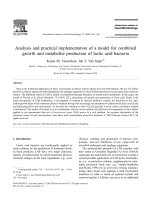
interaction volume Ve that minimizes charging[3],[16], as shown in Figure A.1.
3 2
4
1
Ve
5
6
Key
1 electron interaction volume Ve within which there is a conductive pathway for current flow that yields a stable surface
potential
2 volume of specimen within which the detected Auger electrons are generated
3 vacuum
4 insulator
5 conductive layer
6 electrical contact to specimen mount
Figure A.1 — Schematic drawing showing the conduction pathway created through an insulating layer
by a penetrating electron beam (adapted from Reference [45])
10 © ISO 2010 – All rights reserved
ISO 29081:2010(E)
A.3.3.4 Conduction paths — Masks, meshes, coatings and deposits
Another method of providing a pathway to ground is to minimize the distance between the area irradiated by
the incident electron beam and a conductor connected to ground[2],[3]. This can be accomplished by placing a
mask or grid on the specimen surface around the region to be analysed during specimen mounting. It is also
possible to temporarily cover the region to be analysed and coat the remainder of the specimen with a
conducting layer. If the outer surface is not the primary region of interest, the whole specimen may be coated
and a portion of the coating removed by sputtering. By collecting AES spectra near the region of the conductor,
the path (resistance) between the surface being examined and ground is minimized, and surface charging can
sometimes be avoided. Although this approach can lower the resistivity of the specimen (similar to decreasing
the specimen thickness z), some manipulations are also likely to increase the capacitance of the specimen,
thereby also lowering the tendency towards build-up of surface potential.
The advent of FIB or electron-beam-stimulated chemical-vapour deposition is a new way to deposit a metal on
the surface of interest[17]. By depositing Pt “wires” on a printed-circuit board, it has been possible to analyse
materials in regions isolated from ground using AES without the normal charging difficulties.
A.3.4 Reducing the current density, limiting primary-electron dose and using additional
current sources
A.3.4.1 Current density
In some circumstances, it has been found useful to reduce the primary-electron current density on the
specimen[3]. This might be accomplished by defocusing or rastering the electron beam. Cazaux[12] notes that
the rastered focused beam retains some TSEEY difficulties and is not as effective as a defocused beam in
reducing charging. An obvious disadvantage of this approach is that the spatial resolution will be degraded to
a value that may be inconsistent with the analysis needs. In addition, Seah and Spencer[18] showed that, for
some specimen conditions, some aspects of charging were independent of beam-raster size.
A.3.4.2 Total primary-electron dose
The analysis of total secondary-electron emission yield (TSEEY) in A.5.3 notes conditions for different dose-
or time-dependent effects on the surface potential[12]. Seah and Spencer[18] observed the predicted type of
total primary-electron dose threshold for subsurface charging that complicates AES analysis. Their data
showed that there were at least two different charging mechanisms. One occurred almost immediately and
was nearly independent of the primary-beam current density. The second effect depended upon the total dose
of primary electrons on the specimen and was, therefore, time dependent. A specimen that first charged
positively might eventually charge negatively as the total dose increases (see also Figure A.2). Further
recommendations on the total dose are given in A.3.5.
It is also important to note that the amount of electron-induced desorption from a surface (and related
specimen damage) is dependent upon the total dose of primary electrons on the specimen. Tables of dose
thresholds for 10 % change in signal have been published by Pantano and co-workers[19],[20].
A.3.4.3 Use of additional current sources (ions, electrons or photons)
The net current to the specimen can be altered by providing some additional current. The use of low-energy
ion beams to neutralize or at least stabilize the surface potential is one of the new and seemingly powerful
advances that are taking place for charge compensation during AES analysis. It is possible to balance the
electron current (and in theory reduce the net current) to the surface by introducing a positive current of low-
energy ions. This approach was discussed by Hofmann[3] in 1992, but has only recently been routinely
available on commercial AES instruments[14],[21]. Low-energy ions (that produce minimal sputtering) have
been shown to be very effective at minimizing surface charging associated with conducting regions in a non-
conductive matrix, as commonly found during analysis of integrated circuits. This method sometimes has a
persistent effect in that the stability lasts after the ions are turned off[14]. Many aspects of low-energy ion-beam
“neutralization” are not well understood and methods may improve as users gain experience. While a low-
energy ion beam will reduce the net specimen current and stabilize a positive surface potential on the
specimen, thereby allowing stable long-term AES analyses, the ions will not appreciably reduce the
© ISO 2010 – All rights reserved 11
ISO 29081:2010(E)
subsurface charge induced by the primary electrons. Nonetheless, this approach has proven to be a useful
method for AES analyses of insulators.
Low-energy electrons might be useful for producing a surface potential closer to zero and, in some
circumstances, have been found effective[3],[22]. The energies of the electrons used appear to vary from a few
eV to as much as 400 eV[23]. Such low-energy electrons could compensate the charge on a positively charged
surface and produce additional secondary electrons on a negatively charged surface[3],[18].
Ion sputtering and irradiation by ultraviolet light can increase the number of charge carriers within a specimen
and near the specimen surface. Any mobile charge can help neutralize charge build-up on a specimen, but
this may have additional consequences for AES analysis and the collection of the desired information.
It is also worth noting that, for some oxides, the presence of oxygen at low pressures (or the use of ozone)
minimizes electron-beam-induced reduction of the oxide, decreases the build-up of carbon from the ambient
gas, and minimizes the accumulation of surface charge[24]. Other gases may similarly decrease charge build-
up (as commonly observed in environmental secondary-electron microscopes)[25],[26], but such effects have
not been adequately studied or reported for AES.
A.3.5 Optimizing the total secondary-electron emission yield
Charge build-up on the surface depends both on the electron current arriving at the specimen and the total
current leaving the specimen (secondary electrons, including Auger and backscattered electrons). The total
secondary-electron yield from a specimen is, therefore, a complex but highly important property of the
specimen, discussed in more detail in Clause A.5. The schematic data shown in Figures A.2, A.3 and A.4 and
the discussion in A.5.3 show that the total secondary-electron yield σ depends on the primary-electron energy,
the primary-beam angle of incidence θ on the surface, the presence of surface contamination, and the total
electron dose. Both beam energy and incidence angle have traditionally been varied to facilitate AES analyses
of bulk insulators. See Reference [23] for a discussion of the role of angle of incidence on TSEEY. Based on
the model and analysis presented in A.5.3, beam energies and incidence angles that produce σ > 1 result in a
positive surface potential which should allow relatively stable analysis conditions. The experimental results of
Seah and Spencer[18] demonstrate that this model is reasonably valid for a range of clean and well-
characterized insulators (at least for low electron doses). In addition to measuring the short-term surface
potentials for various conditions, Seah and Spencer also examined the longer-term stability and frequently
observed a high-dose effect. They were able to summarize the data collected for each material in a relatively
simple diagram that presents useful combinations of primary-beam energy and θ for the specific materials
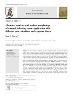
they examined. The low- and high-dose stability diagram for silicon nitride is shown in Figure A.2 and serves
as an example of the considerations relevant for AES analyses of insulating materials.
Data collected by Seah and Spencer[18] include shifts in AES line positions (to give the low-dose curve in
Figure A.2) and the beam energies for which charge accumulation could be observed in secondary-electron
microscopy (SEM) images (high-dose curve in Figure A.2). The authors describe Figure A.2 as a low-dose
and high-dose stability diagram. The figure describes some of the behaviours predicted by the TSEEY model
(see A.5.3). For higher beam energies, charging is observed. The energies for which charging is not present
increase as θ increases. For relatively rapid data collection (that should be typical of many analysis
conditions), Figure A.2 indicates that silicon nitride will not show significant charging for beam voltages below
5,2 kV. As the total electron dose increases, however, charging will occur. At energies of around 2 keV, no
charging effect is observed regardless of dose. The critical energy E and incidence angle for which low-dose
0,6
charging could be observed can be defined by a curve with the form E p c o s θ =N . The higher the value of N,
the higher the energy for which the material will be stable for AES analysis. Seah and Spencer's data suggest
that the form of the equation represents general behaviour of insulating materials but that the particular value
of N will depend on the instrument and the specimen holder in addition to the specimen material and any
surface treatments (see 6.3.4 and A.5.3).
The high-dose region occurs when significant subsurface charge is accumulated in the bulk specimen (see
Figure A.4 and related discussion). The subsurface charge eventually reaches an amount sufficient to change
the TSEEY, the surface charge and thus the surface potential. The measurements summarized in Figure A.2
demonstrate the relationships between beam energy and incidence angle for stable AES analyses. These
measurements also show that charging is a highly complex phenomenon that is not simply explained by a
single TSEEY curve for a material. The secondary-electron yield will vary depending upon the composition of
12 © ISO 2010 – All rights reserved
ISO 29081:2010(E)
the specimen, the experimental configuration and the presence of any surface contamination. It is noted that
carbon has a relatively low secondary-electron yield. Materials highly contaminated by a carbonaceous layer
might be particularly difficult to analyse because it is difficult to obtain a stable surface charge using beam
energy and incidence angle as the primary variables.
Y
80
15
60
4
40
6
20
2 3
0 12 X
0 2 4 6 8 10
Key
X electron-beam energy (keV)
Y angle of incidence, θ (degrees)
1 low-charging zone
2 zone of depth-dependent charging
3 high-charging zone
4 SEM charging data after a large dose
5 line above which charging occurs at a large electron dose
6 line above which shifts occur in the nitrogen Auger peak after a small electron dose
Figure A.2 — Low- and high-dose stability diagram for Si3N4 showing the regions of low charging and
high charging for different combinations of primary-beam energy and angle of incidence θ
(the region between the two will show charging given sufficient electron dose) (from Reference [18])
It should be remembered that alterations of the beam voltage change the relative elemental sensitivity factors
and thus impact quantitative analyses by AES.
Since the surface composition will impact the secondary-electron yield, the presence of surface contaminants
can sometimes have a significant impact on the specimen surface potential[3],[27]. For example, carbon has
been shown to decrease the electron yield and enhance negative surface charge build-up[3],[28],[29]. Geller has
shown that removal of surface carbon (using CO2) on MgO significantly enhanced charge dissipation.
However, specimen cleaning is not a universal solution as, in some circumstances, specimen cleaning by
short durations of ion sputtering has been observed to increase charge build-up.
© ISO 2010 – All rights reserved 13
ISO 29081:2010(E)
A.4 Considerations for highly non-uniform specimens, fibres and particles and the
use of sputter depth profiling
A.4.1 Introduction
This clause briefly discusses special issues or approaches that could apply to highly rough surfaces, fibres,
nanoparticle composites and other non-uniform specimens and the AES analysis during sputter depth profiles
of insulating materials.
A.4.2 Dealing with rough surfaces, particles, fibres and other non-uniform specimens
Much of the analysis above applied to specimens that have uniform composition, and in some cases the
specimens were assumed to be specimens of thick insulating material. These are often not the specimens of
interest for Auger analysis. In general, the use of a focused beam will set up conditions under which the
surface potential on an insulator will vary laterally along the surface. The potential has been described by
Cazaux[12]. Guo et al.[24] have found that AES peaks sometimes split into two parts that can be attributed to
Auger electrons emitted from the centre of the primary beam and those originating from secondary electrons
from the edge of the irradiated zone.
The analysis of finely structured materials is often a high priority for AES analysis. This is a challenging
problem for which there are few general solutions. Situations when local charging prevents the electron beam
from being used to analyse the region of greatest interest are particularly difficult. Although versions of the
approaches described above can be applied, the multiple-flux approaches and ion-beam-thinned specimens
are among the newer methods being used for analysis of these types of specimen. Although there are no
general solutions, many different approaches have been found useful for specific specimens.
Specimens containing small insulating particles or fibres, as well as insulating specimens with rough surfaces,
often exhibit differential charging during AES analyses. Clearly, it is much more difficult to control the local
primary-beam incidence angle for such specimens. However, if the particles or fibres have sufficiently small
diameters and can be mounted in a single layer on a conducting substrate, they can be treated as a thin film
(see A.3.3.3), and minimal charging will be observed. It is often useful to press powders, particles and fibres
into a soft conducting metal such as indium[2] or onto double sticky conducting tape. For rough surfaces, Park
recommends focusing the primary-electron beam on the top of the most prominent protrusion[31].
Some of the newly developing technologies seem particularly useful for examining small features in
specimens containing both conducting and non-conducting regions. Specimens with fine features, including
those buried below the surface, can sometimes be identified and analysed using an FIB and argon-ion cross-
section specimen preparation, in combination with thinning or other charge-compensation
approaches[11],[13],[32]. Because of damage and sputter effects, the use of sputter-based thinning methods
must be applied with caution. When the thin-film specimens are mounted on a low electron-scattering support
such as carbon, the effects of backscattered electrons on lateral resolution in AES are minimized[13],[33],[34].
The use of low-energy positive ions also appears quite effective in allowing analysis of conducting regions in a
non-conducting matrix. Improved lateral resolution is obtained for both imaging and point AES analyses[14],[21].
A.4.3 Sputter depth profiling
The use of AES in combination with ion milling to obtain sputter depth profiles of the near-surface region of
many types of material, including poorly conducting materials, has been one of the major uses of the
technique. One early application of the depth profiling of insulating materials was for weathered or corroded
glasses[35],[36]. Researchers routinely used the range of methods described above to minimize charging when
profiling bulk or thick films of insulating materials. During sputter profiling of glasses, specimens were
commonly tilted away from the normal of the electron beam and low-energy electrons were added to stabilize
the specimen surface potential and AES signals[35]. It might seem that the application of a positive-ion beam
during sputtering in addition to the negative electrons could help stabilize the surface. However, Borchardt et
al.[32] note that ion sputtering can perturb the surface and near-surface charge build-up that would normally
occur during AES analysis of an insulator (described above), and the overall effect on surface potential and
compositional stability is difficult to assess.
14 © ISO 2010 – All rights reserved