ASTM D120-22 Standard Specification for Rubber Insulating Gloves
Bạn đang xem bản rút gọn của tài liệu. Xem và tải ngay bản đầy đủ của tài liệu tại đây (229.21 KB, 9 trang )
This international standard was developed in accordance with internationally recognized principles on standardization established in the Decision on Principles for the
Development of International Standards, Guides and Recommendations issued by the World Trade Organization Technical Barriers to Trade (TBT) Committee.
Designation: D120 − 22
Standard Specification for
Rubber Insulating Gloves1
This standard is issued under the fixed designation D120; the number immediately following the designation indicates the year of
original adoption or, in the case of revision, the year of last revision. A number in parentheses indicates the year of last reapproval. A
superscript epsilon (´) indicates an editorial change since the last revision or reapproval.
This standard has been approved for use by agencies of the U.S. Department of Defense.
1. Scope D297 Test Methods for Rubber Products—Chemical Analy-
sis
1.1 This specification covers manufacturing and testing of
rubber insulating gloves for protection of workers from elec- D412 Test Methods for Vulcanized Rubber and Thermoplas-
trical shock. tic Elastomers—Tension
1.2 Two types of gloves are provided and are designated as D573 Test Method for Rubber—Deterioration in an Air
Type I, non-resistant to ozone, and Type II, resistant to ozone. Oven
1.3 Six classes of gloves, differing in electrical D624 Test Method for Tear Strength of Conventional Vul-
characteristics, are provided and are designated as Class 00, canized Rubber and Thermoplastic Elastomers
Class 0, Class 1, Class 2, Class 3, and Class 4.
D1415 Test Method for Rubber Property—International
1.4 The values stated in SI units are to be regarded as Hardness
standard. The values given in parentheses after SI units are
provided for information only and are not considered standard. D2240 Test Method for Rubber Property—Durometer Hard-
See IEEE/ASTM SI 10. ness
1.5 The following safety hazards caveat pertains only to the F819 Terminology Relating to Electrical Protective Equip-
test method portion, Sections 16, 17, 18, and 19, of this ment for Workers
specification: This standard does not purport to address all of
the safety concerns, if any, associated with its use. It is the IEEE/ASTM SI 10 American National Standard for Metric
responsibility of the user of this standard to establish appro- Practice
priate safety, health, and environmental practices and deter-
mine the applicability of regulatory limitations prior to use. 3. Terminology
For a specific warning statement, see 18.2.
3.1 Definitions:
1.6 This international standard was developed in accor- 3.1.1 color splash—a splash, smear, or streak of contrasting
dance with internationally recognized principles on standard- color evident on the inside or outside surface of the gloves that
ization established in the Decision on Principles for the was deposited during the dipping operation and is vulcanized
Development of International Standards, Guides and Recom- into the glove as part of the homogenous compound.
mendations issued by the World Trade Organization Technical
Barriers to Trade (TBT) Committee. 3.1.2 glove cuff roll—the roll or reinforced edge of an
insulating glove at the cuff.
2. Referenced Documents
2.1 ASTM Standards:2 3.1.3 halogenation treatment—exposure of the entire glove
surface area to a halogen for the purpose of reducing surface
1 This specification is under the jurisdiction of ASTM Committee F18 on friction.
Electrical Protective Equipment for Workers and is the direct responsibility of
Subcommittee F18.15 on Worker Personal Equipment. This standard replaces ANSI 3.1.4 ozone—a very active form of oxygen that may be
Standard J 6.6, which is no longer available. produced by corona, arcing, or ultraviolet rays.
Current edition approved Feb. 1, 2022. Published March 2022. Originally 3.1.5 user—the employer or entity purchasing the equip-
approved in 1921. Last previous edition approved in 2021 as D120 – 21. DOI: ment to be utilized by workers for their protection; in the
10.1520/D0120-22. absence of such an employer or entity, the individual purchas-
ing and utilizing the protective equipment.
2 For referenced ASTM standards, visit the ASTM website, www.astm.org, or
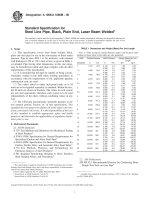
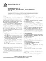
contact ASTM Customer Service at For Annual Book of ASTM 3.1.6 working area—all finger and thumb crotches, the palm
Standardsvolume information, refer to the standard’s Document Summary page on (area between the wrist and the base of the finger and thumb)
the ASTM website. and the area of the finger and thumb facing the palm not
extending beyond the center line of the crotch. See Fig. 1.
3.1.7 For definitions of other terms, refer to Terminology
F819.
Copyright © ASTM International, 100 Barr Harbor Drive, PO Box C700, West Conshohocken, PA 19428-2959. United States
1
D120 − 22
FIG. 1 Working Area of a Rubber Insulating Glove
TABLE 1 Proof-Test/Use Voltage Relationship 4.4 It is common practice and the responsibility of the user
of this type of protective equipment to prepare complete
AC Proof-Test Maximum AC DC Proof-Test Maximum DC Use instructions and regulations to govern the correct and safe use
Class of Glove Voltage, rms, V Use Voltage ac Voltage, avg, V Voltage avg, V of such equipment.
rms, V 5. Classification
00 2 500 500 10 000 750 5.1 Gloves covered under this specification shall be desig-
nated as Type I or Type II; Class 00, Class 0, Class 1, Class 2,
0 5 000 1 000 20 000 1 500 Class 3, or Class 4.
1 10 000 7 500 40 000 11 250 5.1.1 Type I, non-resistant to ozone, made from a high-grade
cis-1,4-polyisoprene rubber compound of natural or synthetic
2 20 000 17 000 50 000 25 500 origin, properly vulcanized.
3 30 000 26 500 60 000 39 750 5.1.2 Type II, ozone-resistant made of any elastomer or
combination of elastomeric compounds.
4 40 000 36 000 70 000 54 000
5.1.3 The class designation shall be based on the electrical
4. Significance and Use properties as shown in Table 2 and Table 3.
4.1 This specification covers the minimum electrical, 6. Ordering Information
chemical, and physical properties guaranteed by the manufac-
turer and the detailed procedures by which such properties are 6.1 Orders for gloves under this specification should include
to be determined. The purchaser has the option to perform or the following information:
have performed any of these tests in order to verify the
guarantee. Claims for failure to meet the specification are 6.1.1 Type,
subject to verification by the manufacturer. 6.1.2 Class,
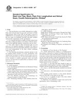
6.1.3 Length, Fig. 2
4.2 Gloves are used for personal protection; therefore, when 6.1.4 Size,
authorizing their use, a margin of safety shall be allowed 6.1.5 Color,
between the maximum voltage on which they are used and the 6.1.6 Cuff design, and
proof-test voltage at which they are tested. The relationship 6.1.7 With or without a halogenation treatment.
between proof-test voltage and the maximum voltage at which
the gloves shall be used is shown in Table 1. 6.2 The listing of types, classes, lengths, sizes, colors, and
cuff designs is not intended to mean that all shall necessarily be
4.3 Work practices vary from user to user and are dependent available from manufacturers; it signifies only that, if made,
upon many factors. These may include, but are not limited to, they shall conform to the details of this specification.
operating system voltages, construction design, work proce-
dure techniques, weather conditions, and so forth. Therefore,
except for the restriction set forth in this specification because
of design limitations, the use and maintenance of this equip-
ment is beyond the scope of this specification.
2
D120 − 22
TABLE 2 AC Voltage Requirement Proof Test CurrentsA
Proof-Test Minimum Maximum Proof-Test Current, mA
Voltage, Breakdown
Class of rms, V 280 mm 360 mm 410 mm 460 mm
Glove Voltage, (11-in.) Glove (14-in.) Glove (16-in.) Glove (18-in.) Glove
rms, V
50 Hz 60 Hz 50 Hz 60 Hz 50 Hz 60 Hz 50 Hz 60 HZ
00 2 500 4 000 6.7 8 10 12 B B B B
0 5 000 6 000 6.7 8 10 12 11.7 14 13.3 16
1 10 000 20 000 ... ... 11.7 14 13.3 16 15 18
2 20 000 30 000 ... ... 13.3 16 15 18 16.7 20
3 30 000 40 000 ... ... 15 18 16.7 20 18.3 22
4 40 000 50 000 ... ... ... ... 18.3 22 20 24
A Proof test current shall be measured to an accuracy of ±1 mA.
B Not applicable.
TABLE 3 DC Voltage Requirements 8.3.1 Standard lengths for Class 00 gloves are 280 mm (11
in.), and 360 mm (14 in.). The permissible variations shall be
Class of Glove Proof-Test Minimum Breakdown 613 mm (61⁄2 in.).
Voltage avg V Voltage avg V
8.3.2 Standard lengths for Class 0 gloves are 280 mm (11
00 10 000 13 000 in.), 360 mm (14 in.), 410 mm (16 in.), and 460 mm (18 in.).
The permissible variations shall be 613 mm (61⁄2 in.).
0 20 000 35 000
8.3.3 Standard lengths for Class 1, 2, and 3 gloves are 360
1 40 000 60 000 mm (14 in.), 410 mm (16 in.), and 460 mm (18 in.). The
permissible variation shall be 613 mm (61⁄2 in.).
2 50 000 70 000
8.3.4 Standard lengths for Class 4 gloves are 410 mm (16
3 60 000 80 000 in.) and 460 mm (18 in.). The permissible variation shall be
613 mm (61⁄2 in.).
4 70 000 90 000
9. Workmanship and Finish
7. Manufacture and Marking
9.1 Gloves shall be free on both inner and outer surface of
7.1 The gloves shall be produced by a seamless process. harmful physical irregularities that can be detected by thorough
test and inspection.
7.2 The gloves shall have a smooth finish and the cuff edges
shall be finished with a roll or a reinforcing strip of rubber, 9.1.1 Harmful physical irregularities may be defined as any
unless otherwise specified. feature that disrupts the uniform, smooth surface contour and
represents a potential hazard to the user, such as pinholes,
7.3 Each glove shall be marked clearly and permanently cracks, blisters, cuts, conductive embedded foreign matter,
with the name of the manufacturer or supplier, ASTM D120, creases, pinch marks, voids (entrapped air), prominent ripples,
type, class, and size. All such marking shall be confined to the and prominent mold marks.
cuff portion of the glove and shall be nonconducting and
applied in such a manner as to not impair the required 9.2 Nonharmful physical irregularities may be defined as
properties of the glove. surface irregularities present on the inner and outer surfaces of
the rubber glove due to imperfections on forms or molds and
7.3.1 Each glove shall be marked with a label that gives the inherent difficulties in the manufacturing process. These irregu-
information specified in 7.3. This label shall be the color larities may appear as mold marks that look like cuts even
specified for each voltage class: Class 00—beige, Class though they are actually a raised ridge of rubber, indentations,
0—red, Class 1—white, Class 2—yellow, Class 3—green, and protuberances, embedded foreign material, or color splashes
Class 4—orange. that are acceptable provided that:
7.4 At the request of the user, the gloves may be given a 9.2.1 The indentations, protuberance or mold marks tend to
halogenation treatment to reduce surface friction. This treat- blend into a smooth slope upon stretching of the material.
ment shall have no detrimental effect on the electrical,
chemical, or physical properties of the gloves. 9.2.2 The rubber thickness at any irregularity conforms to
the thickness requirements.
8. Dimensions and Permissible Variations
9.2.3 Foreign material remains in place when the glove is
8.1 Sample gloves selected in accordance with 13.2 shall folded and stretched with the material surrounding it.
fall within the thickness limits specified in Table 4, when
determined in accordance with 17.1. 9.2.4 Color splashes are no larger than 1 mm in any
direction on the inner surface of the work area.
8.2 Sample gloves selected in accordance with 13.2 shall
conform to standard sizes when determined in accordance with 9.2.4.1 The working area is defined as all finger and thumb
17.2. Standard sizes are 203 mm (8 in.), 216 mm (81⁄2 in.), 229 crotches, the palm (area between the wrist and the base of the
mm (9 in.), 241 mm (91⁄2 in.), 254 mm (10 in.), 267 mm (101⁄2 finger and thumb) and the area of the finger and thumb facing
in.), 279 mm (11 in.), 292 mm (111⁄2 in.), and 305 mm (12 in.). the palm not extending beyond the center line of the crotch.
The permissible variation in size shall be 613 mm (61⁄2 in.). See Fig. 1.
8.3 Sample gloves selected in accordance with 13.2 shall
conform to standard lengths when measured in accordance
with 17.3.
3
D120 − 22
FIG. 2 Length and Contour Measurements on Contour Cuff Gloves
TABLE 4 Thickness Measurements 11. Electrical Requirements
Minimum Thickness Maximum Thickness 11.1 Each glove shall be given a proof test and shall
withstand the 50-Hz or 60–Hz AC proof-test voltage (rms
Class of In Crotch Other Than Crotch value) or the dc proof-test voltage (average value) specified in
Glove Table 2 or Table 3. The proof test shall be performed in
mm in. mm in. mm in. accordance with Section 18. The test voltage shall be applied
00 continuously for 3 min.
0 0.20 0.008 0.25 0.010 0.75 0.030
1 11.1.1 When the ac proof test is used, the 60-Hz proof-test
2 0.46 0.018 0.51 0.020 1.02 0.040 current shall not exceed the values specified in Table 2 at any
3 time during the test period. (Note 1).
4 0.63 0.025 0.76 0.030 1.52 0.060
11.2 Sample gloves selected in accordance with 13.2 shall
1.02 0.040 1.27 0.050 2.29 0.090 not break down at voltages below those specified in Table 2 or
Table 3 when tested in accordance with Section 18.
1.52 0.060 1.90 0.075 2.92 0.115
11.2.1 Gloves that have been subjected to a minimum
2.03 0.080 2.54 0.100 3.56 0.140 breakdown voltage test shall not be used for electric protection.
Proof test current shall be measured to an accuracy of 61 mA.
10. Chemical and Physical Requirements
11.3 Sample gloves selected in accordance with 13.2 shall
10.1 Glove test material taken from sample gloves selected be subjected to a 50-Hz or 60–Hz AC moisture absorption/
in accordance with 13.3 shall conform to physical requirements proof test in accordance with Section 18.
in Table 5 and the accelerated aging in 19.2.6.
11.3.1 The 50-Hz or 60–Hz AC proof test current shall not
10.2 In the event of a dispute, the identification of the rubber exceed the values specified in Table 2 by more than 2 mA.
polymer in Type I gloves shall be performed in accordance
with 19.1. NOTE 1—A proof-test current is an indication of the validity of the
glove make-up, the dielectric constant of the type of material used, the
10.3 Type II glove test material taken from sample gloves thickness, and the total contact area under test.
selected in accordance with 13.3 shall show no visible effects
of ozone when tested in accordance with 18.6. Any visible 12. Guarantee
signs of ozone deterioration of the glove material, such as
checking, cracking, breaks, pitting, and so forth, shall be 12.1 The manufacturer or supplier shall replace, without
considered as evidence of failure to meet the requirements of charge to the purchaser, unused gloves which, at any time
Type II gloves. within a period of nine (9) months from date of initial delivery
of shipment to the purchaser or his designee, fail to pass the
TABLE 5 Physical Requirements tests in this specification. This guarantee will be binding on the
manufacturer or supplier only if the gloves have been properly
Property Type I Type II stored and have not been subjected to more than an original
acceptance test and one retest.
Tensile strength, min, Die C, MPa (psi) 17.2 (2500) 10.3 (1500)
Tensile stress at 200 %, max, MPa (psi) 2.1 (300) 2.1 (300)
Ultimate elongation, min, % 600 500
Tension set, max at 400, % 25 25
Tear resistance, min, kN/m (lbf/in.) 21 (120) 14 (80)
Puncture resistance, min, kN/m (lbf/in.) 18 (100) 18 (100)
Hardness, max, shore A 47 47
4
D120 − 22
12.2 Any acceptance test made by the purchaser, or the been furnished, the manufacturer or supplier may request that
purchaser’s designee, shall be performed within the first two his representative witness the testing of additional gloves from
(2) months of the guarantee period unless otherwise specified. the shipment.
NOTE 2—Proper storage means that gloves are stored right side out, not 14.5 The entire lot or shipment may be rejected at the option
distorted and not stored directly above or in proximity to steam pipes, of the purchaser if two specimens of the first sample and one
radiators, or other sources of artificial heat, or exposed to direct sunlight of the second sample, selected in accordance with 13.3, fail any
or other sources of ozone. It is desirable that the ambient storage of the separate requirements outlined in Section 10.
temperature shall not exceed 35 °C (95 °F).
14.6 The entire lot or shipment of gloves may be rejected at
13. Sampling the option of the purchaser if 25 % of the gloves in the lot or
shipment fail to meet the requirements of Section 8 or 9.
13.1 Each glove in a lot or shipment shall be subjected to
inspection and test to meet the requirements of Sections 7, 14.7 All rejected material shall be returned as directed by
11.1, 9, and 15. the manufacturer, at his or the supplier’s request, without being
defaced by rubber stamp or other permanent marking.
13.2 An original sample of 1 % of the lot or shipment or not However, those gloves punctured when tested in accordance
less than two gloves, whichever is greater, shall be selected at with 11.1, 11.2, and 11.3 shall be stamped, punched, or cut
random from the lot or shipment for the test requirements of prior to being returned to the supplier to indicate that they are
11.2, 11.3 and Section 8. Where a failure occurs in the first unfit for electrical use.
sample, a second sample of the same quantity shall be selected
and tested. 15. Packaging and Package Marking
13.3 An original sample of 0.1 % of the lot or shipment or 15.1 Each pair of gloves shall be packaged in an individual
not less than two gloves, whichever is greater, shall be selected container of sufficient strength to properly protect the gloves
at random from the lot or shipment for the test requirements of from damage in transit. The end of the container shall be
Sections 10.1 and 10.3. marked with the name of the manufacturer or supplier, type,
class, length, size, color, and cuff design.
14. Rejection
TEST METHODS
14.1 Individual gloves shall be rejected if they fail to meet
the requirements of Sections 7, 9 and 11.1 and the minimum 16. Sequence of Testing
thickness requirements of 8.1.
16.1 The following order of procedure is suggested for
14.2 Individual gloves may be rejected at the option of the testing rubber insulating gloves:
purchaser if they fail to meet the requirements of Sections 8
and 15. 16.1.1 Inspection of the surfaces in accordance with Section
9.
14.3 The entire lot or shipment of gloves shall be rejected
under any of the following conditions: 16.1.2 The dimensions in accordance with Section 17.
16.1.3 Electrical proof tests in accordance with 18.4.2 or
14.3.1 If 5 % or more, but not less than two gloves, in a lot 18.5.2.
or shipment fail to meet the requirements of 11.1. 16.1.4 AC moisture absorption/proof test in accordance
with 18.4.4.
14.3.2 If two gloves in the first sample fail to meet the 16.1.5 Breakdown voltage tests in accordance with 18.4.3
requirements of 11.2. or 18.5.3.
16.1.6 Ozone resistance tests in accordance with 18.6.
14.3.3 If one glove in the original sample and one or more 16.1.7 Chemical and physical property tests in accordance
gloves in the second sample fail to meet the requirements of with Section 19.
11.2.
17. Dimension Measurements
14.3.4 If the sample of Type II gloves, using the sampling
methods of 13.3, fails to meet the requirements of 10.3. 17.1 Thickness:
17.1.1 Thickness measurements shall be made at four or
14.3.5 If the proof test current on two gloves in the first more points on the palm side, four or more points on the back
sample do not meet the requirements of 11.3. side, one or more points in the crotch of the thumb and index
finger, and one or more points in the crotches between the
14.3.6 If the proof test current on one glove in the original fingers. See Table 4.
sample and the proof test current on one or more gloves in the 17.1.2 Thickness measurements shall be made on complete
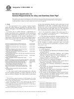
second sample fail to meet the requirements of 11.3. gloves with a micrometer graduated to within 0.025 mm (0.001
in.), having an anvil about 6 mm (0.25 in.) in diameter and a
14.4 The testing shall be terminated and the manufacturer or presser foot of 3.17 mm 6 0.25 mm (0.125 in. 6 0.010 in.) in
supplier notified if, during the course of testing, the gloves in diameter. The presser foot shall exert a total force of 0.83 N 6
a lot or shipment fail to meet the requirements of 10.3, 11.1, 0.03 N (3.0 ozf 6 0.1 ozf).
11.2, or 11.3 as determined by the rejection criteria of 14.3.1,
14.3.2, 14.3.314.3.4, 14.3.5, or 14.3.6. The manufacturer or NOTE 3—A dial-type micrometer graduated in millimetres or inches and
supplier may in such a case require the purchaser to submit
proof that the test procedure and equipment conform to the
appropriate paragraphs of Section 18. When such proof has
5
D120 − 22
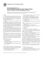
mounted in a manner similar to that shown in Fig. 3 and Fig. 4 is
particularly convenient for making these measurements.
17.1.3 Make sample test specimen thickness measurements
with a similar micrometer, except that the anvil shall be at least
38 mm (1.5 in.) in diameter or, if having a smaller anvil, be
provided with equivalent means of supporting the specimen in
a flat position. In addition, the presser foot shall be 6.3 mm 6
0.3 mm (0.25 in. 6 0.010 in.) in diameter.
17.2 Size shall be the interior circumference of the glove
measured on a line parallel to the finger crotches and passing
through the thumb crotch. The method of determining this
dimension shall be to measure the outside width, W, at this line
with the hand of the glove in a flattened state, subtract twice the
median glove thickness, T, in the hand, and multiply this
difference by a factor of 2:
S 5 2 ~W 2 2T!
where:
S = size of the glove,
W = outside width, and
T = median glove thickness.
17.3 Length:
17.3.1 Length shall be measured with the glove in a relaxed
position and the edge of the cuff perpendicular to the line of
measurement. Length is the distance from the tip of the second
finger to the outside edge of the cuff as shown in Fig. 2 and Fig.
5.
17.3.2 Measure the difference in lengths for contour cuff
gloves with the glove in the same position and along a line
parallel to the length dimensions, as shown in Fig. 2.
FIG. 4 Dial-Type Micrometer for Measuring Glove Thickness at
Fingertips
FIG. 3 Dial-Type Micrometer for Measuring Glove Thickness
6
D120 − 22
FIG. 5 Length Measurement on Standard Cuff Glove
18. Electrical Tests voltage. The test apparatus or each position, or both, should be
protected by an automatic circuit-breaking device designed to
18.1 All electrical tests shall be performed at room tempera- open promptly on the current produced by breakdown of a
ture. The gloves, right side out, shall be filled with tap water specimen under test. This circuit breaking device should be
and immersed in water to a depth in compliance with Table 6 designed to protect the test equipment under any conditions of
for the test voltage to be used. The water level during the test short circuit. The equipment shall be inspected at least annually
shall be the same inside and outside the glove. The water inside to ensure that the general condition of the equipment is
the glove that forms one test electrode shall be connected to acceptable and to verify the characteristics and accuracy of the
one terminal of the voltage source by means of a chain or test voltages. Calibrate the test equipment at least annually
sliding rod that dips into the water. The water in the tank with traceability to NIST (National Institute of Standards and
outside the glove that forms the other electrode shall be Technology).
connected directly to the other terminal of the voltage source.
The water shall be free of air bubbles and air pockets inside or 18.3.1.1 To eliminate damaging ozone and possible flash-
outside the glove, and the exposed portion of the glove above over along the glove cuff, there should be a sufficient flow of
the water line shall be dry. Water used as electrodes shall have air into and around the glove and an exhaust system to
a minimum conductance of 100 µS/cm. adequately remove ozone from the test machine. Consistent
ozone cutting and checking during the test procedure should be
NOTE 4—Both ac and dc voltage proof-test methods are included in this cause to ascertain the adequacy of the exhaust system.
section. It is intended that one method be selected for the electrical tests.
The method selected shall be at the option of the purchaser, and the 18.3.1.2 Glove failure indicators or accessory circuits shall
supplier should be so notified of the selection. be designed to give positive indication of failure and shall
require resetting by the operator before tests can be continued.
18.2 Warning—It is recommended that the test apparatus
be designed to afford the operator full protection in perfor- 18.4 AC Tests:
mance of his duties. Reliable means of de-energizing and 18.4.1 Voltage Supply and Regulation:
grounding the high-voltage circuit shall be provided. It is 18.4.1.1 The desired test voltage may be obtained most
particularly important to incorporate a positive means of readily from a step-up transformer energized from a variable
grounding the high-voltage section of dc test apparatus due to low-voltage source. The transformer and its control equipment
the likely presence of high-voltage capacitance charges at the shall be of such size and design that, with the test specimen in
conclusion of the test. the circuit, the crest factor (ratio of maximum to mean
effective) of the test voltage shall differ by not more than 5 %
18.3 Test Equipment: from that of a sinusoidal wave over the upper half of the range
18.3.1 The test equipment used in the proof, acceptance, of the test voltage.
and dielectric breakdown tests shall be capable of supplying an 18.4.1.2 The accuracy of the voltage measuring circuit shall
essentially stepless and continuously variable voltage to the be within 61 kV of the test voltage. The ac voltage applied to
test specimen. Motor-driven regulating equipment is conve- the test specimen shall be measured with either an ac voltmeter
nient and tends to provide uniform rate-of-rise to the test
TABLE 6 Clearances—Cuff to Water Line A ,B
AC DC
Class of Proof Test Breakdown Proof Test Breakdown
Glove
00 mm in. mm in. mm in. mm in.
0
1 38 11⁄2 38 11⁄2 38 11⁄2 51 2
2
3 38 11⁄2 38 11⁄2 38 11⁄2 51 2
4
38 11⁄2 64 21⁄2 51 2 102 4
64 21⁄2 76 3 76 3 127 5
89 31⁄2 102 4 102 4 152 6
127 5 165 61⁄2 153 6 178 7
A Permissible tolerance clearance – Cuff to water ±13 mm (±1⁄2 in.).
B In those cases where atmospheric conditions make the specified clearances impractical, the clearances may be increased by a maximum of 25 mm (1 in.).
7
D120 − 22
(RMS or average responding) or a peak responding voltmeter 18.5.1.1 The dc test voltage shall be obtained from a dc
calibrated to pk/SQRT2 using one of the following methods: source capable of supplying the required voltage. The peak to
(1) a voltmeter used in conjunction with a calibrated instrument peak ac ripple component of the dc proof-test voltage shall not
transformer connected directly across the high-voltage circuit, exceed 2 % of the average voltage value under no-load
(2) a calibrated electrostatic voltmeter connected directly conditions.
across the high-voltage circuit, or (3) an ac meter connected in
series with appropriate high-voltage type resistors directly 18.5.1.2 Measure the dc proof-test voltage by a method that
across the high-voltage circuit. provides the average value of the voltage applied to the test
specimen. It is recommended that the voltage be measured by
18.4.1.3 The crest factor may be checked by the use of a the use of a dc meter connected in series with appropriate
peak-reading voltmeter connected directly across the high- high-voltage type resistors across the high-voltage circuit. An
voltage circuit; or, if an electrostatic voltmeter or a voltmeter in electrostatic voltmeter of proper range may be used in place of
conjunction with an instrument potential transformer is con- the dc meter-resistor combination. The accuracy of the voltage
nected across the high-voltage circuit, a standard sphere gap measuring circuit shall be within 61 kV of the test voltage.
may be sparked over and the corresponding voltage compared
with the reading of the rms voltmeter. 18.5.2 DC Proof Test:
18.4.1.4 The proof-test current shall be measured by insert- 18.5.2.1 Each glove shall be given a proof test in accor-
ing a milliammeter in series with each individual glove. The dance with the requirements of 11.1. The dc proof-test voltage
reading should be taken near the end of the proof-test period. shall be applied in the same manner as for ac proof tests except
with a rate-of-rise of approximately 3000 V/s.
18.4.2 AC Proof Tests:
18.4.2.1 Each glove shall be given a proof test in accor- 18.5.3 DC Breakdown Test:
dance with the requirements of 11.1. The proof-test voltage
shall be applied initially at a low value and increase at a 18.5.3.1 The dc breakdown tests shall be performed in the
constant rate-of-rise of approximately 1000 V/s until the same way as ac breakdown tests except with a rate-of-rise of
prescribed test voltage level is reached, or failure occurs. The approximately 3000 V/s.
test period starts at the instant that the prescribed testing
voltage is reached. The applied voltage should be reduced to at 18.6 Ozone Resistance Test—The ozone resistance test shall
least half value, unless an electrical failure has occurred, at the be made in accordance with the following method to ensure
end of the test period before opening the test circuit. conformance of Type II gloves with the requirements of 10.3.
18.4.3 AC Breakdown Test:
18.4.3.1 Each sample selected in accordance with 13.2 shall 18.6.1 The ozone resistance test shall be made on a 100 mm
be given a breakdown test as specified in 11.2. The voltage by 150 mm (4-in. by 6-in.) specimen of the glove material
shall be applied at a low value and increase at a constant prepared from a sample suitably conditioned by lying flat for
rate-of-rise of approximately 1000 V/s until the prescribed 24 h. The specimen should be draped over a 25 mm (1-in.)
minimum breakdown voltage is reached or failure occurs. The diameter metal tube of sufficient length to completely underlie
maximum voltage observed prior to failure shall be considered the specimen, while possessing additional length for the
as the breakdown voltage. required mounting supports. The metal tubing shall be electri-
18.4.4 AC Moisture Absorption/Proof Test: cally grounded. The free ends of the specimen shall be clamped
18.4.4.1 Each sample selected in accordance with 13.2 shall beneath the tubing electrode so that an intimate contact is
be given an AC moisture absorption/proof test as specified in established between the specimen and the tubing along the
11.3. Sample gloves that have passed the ac proof test upper half of the cylindrically-shaped electrode surface.
requirement of 18.4.2 shall be placed in the test equipment,
immersed in water in accordance with 18.1 and soaked for 16 18.6.2 A piece of flat aluminum sheet foil, approximately 50
h. Alternately, the gloves may be soaked by submerging mm by 100 mm (2 in. by 4 in.), shall be placed over the draped
completely in water without trapping air and then transferring specimen so as to provide adequate separation distance to
them directly to the test equipment in accordance with 18.1. prevent flashover between the foil and the metal tubing. An
The gloves will be soaked for 16 continuous hours at room electrode wire shall be connected to the aluminum foil.
temperature. Immediately after the soak period, the proof test
voltage shall then be applied initially at a low value and 18.6.3 The outer electrode (metal foil) shall be energized to
increased at a constant rate-of-rise of approximately 1000 V/s 15 kV ac (rms) from a stable 60-Hz source. The 15 kV
until the prescribed test voltage level is reached or failure potential may be derived from a suitably rated potential
occurs. The proof test current shall then be measured and transformer energized from its low-voltage winding through a
recorded. The applied voltage shall then be reduced to at least continuously variable autotransformer. An overcurrent protec-
half value, unless an electrical failure has occurred, before tive device should be incorporated into the low-voltage control
opening the test circuit. circuit in case of an electrical breakdown.
NOTE 5—If an alternate method is used, ensure that the clearance area 18.6.4 The ozone resistance of the specimen should be
is dry to avoid flashover. determined qualitatively, by inspection, after a 1-h exposure
period in the test apparatus at the 15 kV potential. At least two
18.5 DC Tests: specimens from each sample glove selected in accordance with
18.5.1 Voltage Supply and Regulation: 13.2 shall be tested. Two specimens should not be taken from
the same section of the sample glove.
NOTE 6—The rate of ozone degradation is inversely proportional to the
relative humidity of the surrounding air. Empirical data indicate, however,
that visible ozone effects will be evident over a broad range of ambient
humidities under these test conditions.
8
D120 − 22
19. Chemical and Physical Tests shall have an opening 25 mm (1.0 in.) in diameter to provide
a fixed free area through which the specimen can elongate
19.1 Chemical Tests: while being subjected to the pressure of the needle point. The
19.1.1 The composition of the rubber hydrocarbon portion edges of the openings should be rounded to a radius of
of Type I gloves may be determined in accordance with the test approximately 0.8 mm (0.03 in.). The needle shall be made
method in Methods D297. from 5 mm (0.19-in.) diameter Type 304 stainless steel rod.
The rod should be machined at one end to produce a taper with
19.2 Physical Tests: an included angle of 12° with the tip of the tapered end rounded
19.2.1 Physical tests should be performed to determine the to a radius of 0.8 mm (0.03 in.). The needle shall be initially
physical requirements specified in Section 10. The glove positioned perpendicularly to the specimen so that the point
samples should be conditioned by storing in a flat position for contacts the specimen through the small hole in the plate. The
24 h at a room temperature of 23 6 4 °C (73 6 7 °F). needle shall be driven into and through the specimen at a
19.2.2 The tensile strength, tensile stress at 200 % of continuous rate of approximately 8.3 mm/s (20 in./min). The
elongation, and tension set tests shall be performed in accor- maximum force required to perform the puncturing operation
dance with Test Methods D412, except for elongation time. shall be measured to the nearest 2 N (0.5 lbf). The puncture
The test specimen shall conform in dimensions to Die C. The resistance shall be calculated by dividing the puncturing force
elongation in the tension set shall be 400 % with grip separa- by the specimen thickness and recorded in units of newtons per
tion at a rate of 500 mm 6 50 mm (20 in. 6 2)/min. metre (or pounds-force per inch).
19.2.3 The tear resistance test shall be performed in accor-
dance with Test Method D624. The test specimen shall 19.2.5 The durometer test shall be performed in accordance
conform to the dimensions of Die C. with Test Method D1415 or Test Method D2240, using a Type
19.2.4 The puncture resistance test shall be performed to A durometer.
determine the ability of the glove material to withstand
puncture. 19.2.6 The accelerated aging tests shall be performed in
19.2.4.1 A glove specimen shall be cut to fit between the accordance with Test Method D573. After being subjected to a
opposing faces of two flat metal plates having concentric temperature of 70 6 2 °C (158 6 3.6 °F) in circulating air for
openings. The thickness of each test specimen shall be mea- 7 days, the tensile strength and elongation of the specimen
sured at its approximate center using a micrometer having the shall not be less than 80 % of the original.
characteristics described in Test Methods D412. One of the
plates shall have a circular opening 6 mm (0.25 in.) in diameter 20. Keywords
to allow the passage of a stainless steel needle. The other plate
20.1 electrical insulating gloves; lineman; lineman protec-
tive equipment
ASTM International takes no position respecting the validity of any patent rights asserted in connection with any item mentioned
in this standard. Users of this standard are expressly advised that determination of the validity of any such patent rights, and the risk
of infringement of such rights, are entirely their own responsibility.
This standard is subject to revision at any time by the responsible technical committee and must be reviewed every five years and
if not revised, either reapproved or withdrawn. Your comments are invited either for revision of this standard or for additional standards
and should be addressed to ASTM International Headquarters. Your comments will receive careful consideration at a meeting of the
responsible technical committee, which you may attend. If you feel that your comments have not received a fair hearing you should
make your views known to the ASTM Committee on Standards, at the address shown below.
This standard is copyrighted by ASTM International, 100 Barr Harbor Drive, PO Box C700, West Conshohocken, PA 19428-2959,
United States. Individual reprints (single or multiple copies) of this standard may be obtained by contacting ASTM at the above
address or at 610-832-9585 (phone), 610-832-9555 (fax), or (e-mail); or through the ASTM website
(www.astm.org). Permission rights to photocopy the standard may also be secured from the Copyright Clearance Center, 222
Rosewood Drive, Danvers, MA 01923, Tel: (978) 646-2600; />
9