ASTM D150-11 Standard Test Methods for AC Loss Characteristics and Permittivity (Dielectric Constant) of Solid Electrical Insulation
Bạn đang xem bản rút gọn của tài liệu. Xem và tải ngay bản đầy đủ của tài liệu tại đây (595.94 KB, 20 trang )
This international standard was developed in accordance with internationally recognized principles on standardization established in the Decision on Principles for the
Development of International Standards, Guides and Recommendations issued by the World Trade Organization Technical Barriers to Trade (TBT) Committee.
Designation: D150 − 22
Standard Test Methods for
AC Loss Characteristics and Permittivity (Dielectric
Constant) of Solid Electrical Insulation1
This standard is issued under the fixed designation D150; the number immediately following the designation indicates the year of
original adoption or, in the case of revision, the year of last revision. A number in parentheses indicates the year of last reapproval. A
superscript epsilon (´) indicates an editorial change since the last revision or reapproval.
This standard has been approved for use by agencies of the U.S. Department of Defense.
1. Scope* 2. Referenced Documents
2.1 ASTM Standards:4
1.1 These test methods cover the determination of relative D374 Test Methods for Thickness of Solid Electrical Insu-
permittivity, dissipation factor, loss index, power factor, phase lation (Metric) D0374_D0374M
angle, and loss angle of specimens of solid electrical insulating D618 Practice for Conditioning Plastics for Testing
materials when the standards used are lumped impedances. The D1531 Test Methods for Relative Permittivity (Dielectric
frequency range addressed extends from less than 1 Hz to Constant) and Dissipation Factor by Fluid Displacement
several hundred megahertz. Procedures (Withdrawn 2012)5
D1711 Terminology Relating to Electrical Insulation
NOTE 1—In common usage, the word relative is frequently dropped. D5032 Practice for Maintaining Constant Relative Humidity
by Means of Aqueous Glycerin Solutions
1.2 These test methods provide general information on a E104 Practice for Maintaining Constant Relative Humidity
variety of electrodes, apparatus, and measurement techniques. by Means of Aqueous Solutions
A reader interested in issues associated with a specific material
needs to consult ASTM standards or other documents directly 3. Terminology
applicable to the material to be tested.2,3
3.1 Definitions:
1.3 This standard does not purport to address all of the 3.1.1 Use Terminology D1711 for definitions of terms used
safety concerns, if any, associated with its use. It is the in these test methods and associated with electrical insulation
responsibility of the user of this standard to establish appro- materials.
priate safety, health, and environmental practices and deter- 3.2 Definitions of Terms Specific to This Standard:
mine the applicability of regulatory limitations prior to use. 3.2.1 capacitance, C, n—that property of a system of
For specific hazard statements, see 10.2.1. conductors and dielectrics which permits the storage of elec-
trically separated charges when potential differences exist
1.4 This international standard was developed in accor- between the conductors.
dance with internationally recognized principles on standard-
ization established in the Decision on Principles for the 4. Summary of Test Method
Development of International Standards, Guides and Recom-
mendations issued by the World Trade Organization Technical 4.1 Capacitance and ac resistance measurements are made
Barriers to Trade (TBT) Committee. on a specimen. Relative permittivity is the specimen capaci-
tance divided by a calculated value for the vacuum capacitance
1 These test methods are under the jurisdiction of ASTM Committee D09 on (for the same electrode configuration), and is significantly
Electrical and Electronic Insulating Materials and are the direct responsibility of dependent on resolution of error sources. Dissipation factor,
Subcommittee D09.12 on Electrical Tests. generally independent of the specimen geometry, is also
calculated from the measured values.
Current edition approved Sept. 1, 2022. Published October 2022. Originally
approved in 1922. Last previous edition approved in 2018 as D150 – 18. DOI: 4 For referenced ASTM standards, visit the ASTM website, www.astm.org, or
10.1520/D0150-22. contact ASTM Customer Service at For Annual Book of ASTM
Standards volume information, refer to the standard’s Document Summary page on
2 R. Bartnikas, Chapter 2, “Alternating-Current Loss and Permittivity the ASTM website.
Measurements,” Engineering Dielectrics, Vol. IIB, Electrical Properties of Solid
Insulating Materials, Measurement Techniques, R. Bartnikas, Editor, STP 926, 5 The last approved version of this historical standard is referenced on
ASTM, Philadelphia, 1987. www.astm.org.
3 R. Bartnikas, Chapter 1, “Dielectric Loss in Solids,” Engineering Dielectrics,
Vol IIA, Electrical Properties of Solid Insulating Materials: Molecular Structure and
Electrical Behavior, R. Bartnikas and R. M. Eichorn, Editors, STP 783, ASTM
Philadelphia, 1983.
*A Summary of Changes section appears at the end of this standard
Copyright © ASTM International, 100 Barr Harbor Drive, PO Box C700, West Conshohocken, PA 19428-2959. United States
1
D150 − 22
4.2 This method provides (1) guidance for choices of While the initial value of dissipation factor is important, the
electrodes, apparatus, and measurement approaches; and (2) change in dissipation factor with aging is often much more
directions on how to avoid or correct for capacitance errors. significant.
4.2.1 General Measurement Considerations: 5.4 Capacitance is the ratio of a quantity, q, of electricity to
a potential difference, V. A capacitance value is always
Fringing and Stray Capacitance Guarded Electrodes positive. The units are farads when the charge is expressed in
Geometry of Specimens Calculation of Vacuum Capacitance coulombs and the potential in volts:
Edge, Ground, and Gap Corrections
4.2.2 Electrode Systems - Contacting Electrodes
Electrode Materials Metal Foil C 5 q/V (1)
Conducting Paint Fired-On Silver
Sprayed Metal Evaporated Metal 5.5 Dissipation factor ((D), (loss tangent), (tan δ)) is the
Liquid Metal Rigid Metal ratio of the loss index (κ") to the relative permittivity (κ') which
Water is equal to the tangent of its loss angle (δ) or the cotangent of
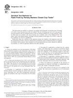
its phase angle (θ) (see Fig. 1 and Fig. 2).
4.2.3 Electrode Systems - Non-Contacting Electrodes
Fixed Electrodes Micrometer Electrodes D 5 κ"/κ' (2)
Fluid Displacement Methods
5.5.1 It is calculated via Eq 3:
4.2.4 Choice of Apparatus and Methods for Measuring
Capacitance and AC Loss D 5 tan δ 5 cotθ 5 Xp/Rp 5 G/ωC p 5 1/ωCpRp (3)
Frequency Direct and Substitution Methods where:
Two-Terminal Measurements Three-Terminal Measurements
Fluid Displacement Methods Accuracy considerations G = equivalent ac conductance,
Xp = parallel reactance,
5. Significance and Use Rp = equivalent ac parallel resistance,
Cp = parallel capacitance, and
5.1 Permittivity—Insulating materials are used in general in ω = 2πf (sinusoidal wave shape assumed).
two distinct ways, (1) to support and insulate components of an
electrical network from each other and from ground, and (2) to The reciprocal of the dissipation factor is the quality factor,
function as the dielectric of a capacitor. For the first use, it is Q, sometimes called the storage factor. The dissipation factor,
generally desirable to have the capacitance of the support as D, of the capacitor is the same for both the series and parallel
small as possible, consistent with acceptable mechanical, representations as follows:
chemical, and heat-resisting properties. A low value of permit-
tivity is thus desirable. For the second use, it is desirable to D 5 ωRsCs 5 1/ωR pCp (4)
have a high value of permittivity, so that the capacitor is able
to be physically as small as possible. Intermediate values of The relationships between series and parallel components
permittivity are sometimes used for grading stresses at the edge are as follows:
or end of a conductor to minimize ac corona. Factors affecting
permittivity are discussed in Appendix X3. Cp 5 Cs/~11D 2! (5)
5.2 AC Loss—For both cases (as electrical insulation and as Rp/Rs 5 ~11D 2!/D2 5 11~1/D2! 5 11Q 2 (6)
capacitor dielectric) the ac loss generally needs to be small,
both in order to reduce the heating of the material and to 5.5.2 Series Representation—While the parallel representa-
minimize its effect on the rest of the network. In high tion of an insulating material having a dielectric loss (Fig. 3) is
frequency applications, a low value of loss index is particularly usually the proper representation, it is always possible and
desirable, since for a given value of loss index, the dielectric occasionally desirable to represent a capacitor at a single
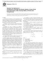
loss increases directly with frequency. In certain dielectric frequency by a capacitance, Cs, in series with a resistance, Rs
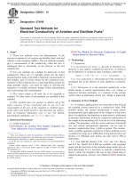
configurations such as are used in terminating bushings and (Fig. 4 and Fig. 2).
cables for test, an increased loss, usually obtained from
increased conductivity, is sometimes introduced to control the 5.6 Loss angle ((phase defect angle), (δ)) is the angle whose
voltage gradient. In comparisons of materials having approxi- tangent is the dissipation factor or arctan κ"/κ' or whose
mately the same permittivity or in the use of any material under cotangent is the phase angle.
such conditions that its permittivity remains essentially
constant, it is potentially useful to consider also dissipation 5.6.1 The relation of phase angle and loss angle is shown in
factor, power factor, phase angle, or loss angle. Factors Fig. 1 and Fig. 2. Loss angle is sometimes called the phase
affecting ac loss are discussed in Appendix X3. defect angle.
5.3 Correlation—When adequate correlating data are FIG. 1 Vector Diagram for Parallel Circuit
available, dissipation factor or power factor are useful to
indicate the characteristics of a material in other respects such
as dielectric breakdown, moisture content, degree of cure, and
deterioration from any cause. However, it is possible that
deterioration due to thermal aging will not affect dissipation
factor unless the material is subsequently exposed to moisture.
2
D150 − 22
PF 5 W/VI 5 G/=G21~ωCp!2 5 sin δ 5 cos θ (8)
When the dissipation factor is less than 0.1, the power factor
differs from the dissipation factor by less than 0.5 %. Their
exact relationship is found from the following:
PF 5 D/=11D2 (9)
D 5 PF/=1 2 ~PF! 2
FIG. 2 Vector Diagram for Series Circuit 5.10 Relative permittivity ((relative dielectric constant)
(SIC) κ'(εr)) is the real part of the relative complex permittivity.
It is also the ratio of the equivalent parallel capacitance, Cp, of
a given configuration of electrodes with a material as a
dielectric to the capacitance, Cυ, of the same configuration of
electrodes with vacuum (or air for most practical purposes) as
the dielectric:
κ' 5 C p/Cv (10)
NOTE 3—In common usage the word “relative” is frequently dropped.
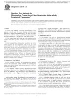
FIG. 3 Parallel Circuit NOTE 4—Experimentally, vacuum must be replaced by the material at
all points where it makes a significant change in capacitance. The
equivalent circuit of the dielectric is assumed to consist of Cp, a
capacitance in parallel with conductance. (See Fig. 3.)
NOTE 5—Cx is taken to be Cp, the equivalent parallel capacitance as
shown in Fig. 3.
FIG. 4 Series Circuit NOTE 6—The series capacitance is larger than the parallel capacitance
by less than 1 % for a dissipation factor of 0.1, and by less than 0.1 % for
a dissipation factor of 0.03. If a measuring circuit yields results in terms
of series components, the parallel capacitance must be calculated from Eq
5 before the corrections and permittivity are calculated.
5.7 Loss index (κ" (εr") is the magnitude of the imaginary NOTE 7—The permittivity of dry air at 23 °C and standard pressure at
part of the relative complex permittivity; it is the product of the 101.3 kPa is 1.000536 (1).6 Its divergence from unity, κ' − 1, is inversely
relative permittivity and dissipation factor. proportional to absolute temperature and directly proportional to atmo-
spheric pressure. The increase in permittivity when the space is saturated
5.7.1 The loss index is expressed as: with water vapor at 23 °C is 0.00025 (2, 3), and varies approximately
linearly with temperature expressed in degrees Celsius, from 10 °C to
κ" 5 κ' D (7) 27 °C. For partial saturation the increase is proportional to the relative
humidity.
5power loss/~E 2 3 f 3 volume 3 constant! 6. General Measurement Considerations
.
6.1 Fringing and Stray Capacitance—These test methods
When the power loss is in watts, the applied voltage is in are based upon measuring the specimen capacitance between
volts per centimeter, the frequency is in hertz, the volume is the electrodes, and measuring or calculating the vacuum capaci-
cubic centimeters to which the voltage is applied, the constant tance (or air capacitance for most practical purposes) in the
has the value of 5.556 × 10⁻¹³. same electrode system. For unguarded two-electrode
measurements, the determination of these two values required
NOTE 2—Loss index is the term agreed upon internationally. In the to compute the permittivity, κx' is complicated by the presence
United States, κ" was formerly called the loss factor. of undesired fringing and stray capacitances which get in-
cluded in the measurement readings. Fringing and stray capaci-
5.8 Phase angle (θ) is the angle whose cotangent is the tances are illustrated by Figs. 5 and 6 for the case of two
dissipation factor, arccot κ"/κ' and is also the angular difference unguarded parallel plate electrodes between which the speci-
in the phase between the sinusoidal alternating voltage applied men is to be placed for measurement. In addition to the desired
to a dielectric and the component of the resulting current direct interelectrode capacitance, Cv, the system as seen at
having the same frequency as the voltage. terminals a-a' includes the following:
5.8.1 The relation of phase angle and loss angle is shown in 6 The boldface numbers in parentheses refer to the list of references appended to
Fig. 1 and Fig. 2. Loss angle is sometimes called the phase these test methods.
defect angle.
5.9 Power factor (PF) is the ratio of the power in watts, W,
dissipated in a material to the product of the effective sinusoi-
dal voltage, V, and current, I, in volt-amperes.
5.9.1 Power factor is expressed as the cosine of the phase
angle θ (or the sine of the loss angle δ).
3
D150 − 22
FIG. 5 Stray Capacitance, Unguarded Electrodes distribution in the guarded area will be identical with that
existing when vacuum is the dielectric, and the ratio of these
FIG. 6 Flux Lines Between Unguarded Electrodes two direct capacitances is the permittivity. Furthermore, the
field between the active electrodes is defined and the vacuum
Ce = fringing or edge capacitance, capacitance can be calculated with the accuracy limited only by
Cg = capacitance to ground of the outside face of each the accuracy with which the dimensions are known. For these
reasons the guarded electrode (three-terminal) method is to be
electrode, used as the referee method unless otherwise agreed upon. Fig.
CL = capacitance between connecting leads, 8 shows a schematic representation of a completely guarded
CLg = capacitance of the leads to ground, and and shielded electrode system. Although the guard is com-
CLe = capacitance between the leads and the electrodes. monly grounded, the arrangement shown permits grounding
either measuring electrode or none of the electrodes to accom-
Only the desired capacitance, Cv, is independent of the modate the particular three-terminal measuring system being
outside environment, all the others being dependent to a degree used. If the guard is connected to ground, or to a guard terminal
on the proximity of other objects. It is necessary to distinguish on the measuring circuit, the measured capacitance is the direct
between two possible measuring conditions to determine the capacitance between the two measuring electrodes. If,
effects of the undesired capacitances. When one measuring however, one of the measuring electrodes is grounded, the
electrode is grounded, as is often the case, all of the capaci- capacitance to ground of the ungrounded electrode and leads is
tances described are in parallel with the desired Cv- with the in parallel with the desired direct capacitance. To eliminate this
exception of the ground capacitance of the grounded electrode source of error, surround the ungrounded electrode with a
and its lead. If Cv is placed within a chamber with walls at shield connected to guard as shown in Fig. 8. In addition to
guard potential, and the leads to the chamber are guarded, the guarded methods, which are not always convenient or practical
capacitance to ground no longer appears, and the capacitance and which are limited to frequencies less than a few megahertz,
seen at a-a' includes Cv and Ce only. For a given electrode techniques using special cells and procedures have been
arrangement, the edge capacitance, Ce, can be calculated with devised that yield, with two-terminal measurements, accuracies
reasonable accuracy when the dielectric is air. When a speci- comparable to those obtained with guarded measurements.
men is placed between the electrodes, the value of the edge Such methods described here include shielded micrometer
capacitance can change requiring the use of an edge capaci- electrodes (7.3.2) and fluid displacement methods (7.3.3).
tance correction using the information from Table 1. Empirical
corrections have been derived for various conditions, and these 6.3 Geometry of Specimens—For determining the permittiv-
are given in Table 1 (for the case of thin electrodes such as ity and dissipation factor of a material, sheet specimens are
foil). In routine work, where best accuracy is not required it is preferable. Cylindrical specimens can also be used, but gener-
convenient to use unshielded, two-electrode systems and make ally with lesser accuracy. The source of the greatest uncertainty
the approximate corrections. Since area (and hence Cv) in- in permittivity is in the determination of the dimensions of the
creases of the square diameter while perimeter (and hence Ce) specimen, and particularly that of its thickness. Therefore, the
increases linearly with diameter, the percentage error in per- thickness shall be large enough to allow its measurement with
mittivity due to neglecting the edge correction decreases with the required accuracy. The chosen thickness will depend on the
increasing specimen diameter. However, for exacting measure- method of producing the specimen and the likely variation
ments it is necessary to use guarded electrodes. from point to point. For 1 % accuracy a thickness of 1.5 mm
(0.06 in.) is usually sufficient, although for greater accuracy it
6.2 Guarded Electrodes—The fringing and stray capaci- is desirable to use a thicker specimen. Another source of error,
tance at the edge of the guarded electrode is practically when foil or rigid electrodes are used, is in the unavoidable gap
eliminated by the addition of a guard electrode as shown in Fig. between the electrodes and the specimen. For thin specimens
7 and Fig. 8. If the test specimen and guard electrode extend the error in permittivity can be as much as 25 %. A similar error
beyond the guarded electrode by at least twice the thickness of occurs in dissipation factor, although when foil electrodes are
the specimen and the guard gap is very small, the field applied with a grease, the two errors are not likely to have the
same magnitude. For the most accurate measurements on thin
specimens, use the fluid displacement method (7.3.3). This
method reduces or completely eliminates the need for elec-
trodes on the specimen. The thickness must be determined by
measurements distributed systematically over the area of the
specimen that is used in the electrical measurement and shall
be uniform within 61 % of the average thickness. If the whole
area of the specimen will be covered by the electrodes, and if
the density of the material is known, the average thickness can
be determined by weighing. The diameter chosen for the
specimen shall be such as to provide a specimen capacitance
that can be measured to the desired accuracy. With well-
guarded and screened apparatus there need be no difficulty in
4
D150 − 22
TABLE 1 Calculations of Vacuum Capacitance and Edge Corrections (see 8.5)
NOTE 1—See Table 2 for Identification of Symbols used.
Type of Electrode Direct Inter-Electrode Capacitance Correction for Stray Field at an Edge, pF
in Vacuum, pF Ce = 0
Disk electrodes with guard-ring: A
C v 5ε0 t 5A
0.0088542 t
A5 π4 sd1 1BA gd2
Disk electrodes without guard-ring: where a << t, Ce = (0.0087 – 0.00252 ln t) P
Diameter of the electrodes = diameter of the specimen:
Equal electrodes smaller than the specimen: d 2 1 Ce = (0.0019 κx' – 0.00252 ln t + 0.0068)P
Unequal electrodes: Cv 50.0069541 where: κx' = an approximate value of the specimen permit
Cylindrical electrodes with guard-ring:
t tivity, and a << t.
0.055632 sl1 1BA gd Ce = (0.0041 κx'– 0.00334 ln t + 0.0122)P
where: κx' = an approximate value of the specimen
Cv 5
ln d 2 permittivity, and a << t.
d1
Ce = 0
Cylindrical electrodes without guard-ring: Cv 5 0.055632 l1 t1
A See Appendix X2 for corrections to guard gap. d2 If t1d1 , 10
ln Ce = (0.0038 κx ' – 0.00504 ln t + 0.0136)P
d1 P = π (d1 + t)
where κx' = an approximate value of the specimen
permittivity.
FIG. 8 Three-Terminal Cell for Solids
FIG. 7 Flux Lines Between Guarded Parallel Plate Electrodes factor shall be contributed by the series resistance of the
electrodes and that in the measuring network no large capaci-
measuring specimens having capacitances of 10 pF to a tance shall be connected in parallel with that of the specimen.
resolution of 1 part in 1000. If a thick specimen of low The first of these points favors thick specimens; the second
permittivity is to be tested, it is likely that a diameter of 100 suggests thin specimens of large area. Micrometer electrode
mm or more will be needed to obtain the desired capacitance methods (7.3.2) can be used to eliminate the effects of series
accuracy. In the measurement of small values of dissipation resistance. Use a guarded specimen holder (Fig. 8) to minimize
factor, the essential points are that no appreciable dissipation extraneous capacitances.
5
D150 − 22
6.4 Calculation of Vacuum Capacitance—The practical electrode system is employed. When equal-size electrodes
shapes for which capacitance can be most accurately calculated smaller than the specimen are used, it is difficult to center them
are flat parallel plates and coaxial cylinders, the equations for unless the specimen is translucent or an aligning fixture is
which are given in Table 1. These equations are based on a employed. For three-terminal measurements, the width of the
uniform field between the measuring electrodes, with no guard electrode shall be at least twice the thickness of the
fringing at the edges. Capacitance calculated on this basis is specimen (6, 8). The gap width shall be as small as practical
known as the direct interelectrode capacitance. (0.5 mm is possible). For measurement of dissipation factor at
the higher frequencies, electrodes of this type are likely to be
6.5 Edge, Ground, and Gap Corrections—The equations for unsatisfactory because of their series resistance. Use microm-
calculating edge capacitance, given in Table 1, are empirical, eter electrodes for the measurements.
based on published work (4) (see 8.5). They are expressed in
terms of picofarads per centimetre of perimeter and are thus 7.2 Electrode Materials:
independent of the shape of the electrodes. It is recognized that
they are dimensionally incorrect, but they are found to give 7.2.1 Metal Foil—Lead or tin foil from 0.0075 mm to
better approximations to the true edge capacitance than any 0.025 mm thick applied with a minimum quantity of refined
other equations that have been proposed. Ground capacitance petrolatum, silicone grease, silicone oil, or other suitable
cannot be calculated by any equations presently known. When low-loss adhesive is generally used as the electrode material.
measurements must be made that include capacitance to Aluminum foil has also been used, but it is not recommended
ground, it is recommended that the value be determined because of its stiffness and the probability of high contact
experimentally for the particular setup used. The difference resistance due to the oxidized surface. Lead foil is also likely
between the capacitance measured in the two-terminal arrange- to give trouble because of its stiffness. Apply such electrodes
ment and the capacitance calculated from the permittivity and under a smoothing pressure sufficient to eliminate all wrinkles
the dimensions of the specimen is the ground capacitance plus and to work excess adhesive toward the edge of the foil. One
the edge capacitance. The edge capacitance can be calculated very effective method is to use a narrow roller, and to roll
using one of the equations of Table 1. As long as the same outward on the surface until no visible imprint can be made on
physical arrangement of leads and electrodes is maintained, the the foil. With care the adhesive film can be reduced to 0.0025
ground capacitance will remain constant, and the experimen- mm. As this film is in series with the specimen, it will always
tally determined value can be used as a correction to subse- cause the measured permittivity to be too low and probably the
quently measured values of capacitance. The effective area of dissipation factor to be too high. These errors usually become
a guarded electrode is greater than its actual area by approxi- excessive for specimens of thickness less than 0.125 mm. The
mately half the area of the guard gap (5, 6, 7). Thus, the error in dissipation factor is negligible for such thin specimens
diameter of a circular electrode, each dimension of a rectan- only when the dissipation factor of the film is nearly the same
gular electrode, or the length of a cylindrical electrode is as that of the specimen. When the electrode is to extend to the
increased by the width of this gap. When the ratio of gap width, edge, it shall be made larger than the specimen and then cut to
g, to specimen thickness, t, is appreciable, the increase in the the edge with a small, finely ground blade. A guarded and
effective dimension of the guarded electrode is somewhat less guard electrode can be made from an electrode that covers the
than the gap width. Details of computation for this case are entire surface, by cutting out a narrow strip (0.5 mm is
given in Appendix X2. possible) by means of a compass equipped with a narrow
cutting edge.
7. Electrode Systems7
7.2.2 Conducting Paint—Certain types of high-conductivity
7.1 Contacting Electrodes—It is acceptable for a specimen silver paints, either air-drying or low-temperature-baking
to be provided with its own electrodes, of one of the materials varieties, are commercially available for use as electrode
listed below. For two-terminal measurements, the electrodes material. They are sufficiently porous to permit diffusion of
shall either extend to the edge of the specimen or be smaller moisture through them and thereby allow the test specimen to
than the specimen. In the latter case, it is acceptable for the two condition after application of the electrodes. This is particu-
electrodes to be equal or unequal in size. If they are equal in larly useful in studying humidity effects. The paint has the
size and smaller than the specimen, the edge of the specimen disadvantage of not being ready for use immediately after
must extend beyond the electrodes by at least twice the application. It usually requires an overnight air-drying or
specimen thickness. The choice between these three sizes of low-temperature baking to remove all traces of solvent, which
electrodes will depend on convenience of application of the otherwise has the potential to increase both permittivity and
electrodes, and on the type of measurement adopted. The edge dissipation factor. It is often also not easy to obtain sharply
correction (see Table 1) is smallest for the case of electrodes defined electrode areas when the paint is brushed on, but it is
extending to the edge of the specimen and largest for unequal possible to overcome by spraying the paint and employing
electrodes. When the electrodes extend to the edge of the either clamp-on or pressure-sensitive masks. The conductivity
specimen, these edges must be sharp. Such electrodes must be of silver paint electrodes is often low enough to give trouble at
used, if attached electrodes are used at all, when a micrometer the higher frequencies. It is essential that the solvent of the
paint does not affect the specimen permanently.
7 Additional information on electrode systems can be found in Research Report
RR:D09-1037 available from ASTM Headquarters. 7.2.3 Fired-On Silver—Fired-on silver electrodes are suit-
able only for glass and other ceramics that are able to
withstand, without change, a firing temperature of about
6
D150 − 22
350 °C. Its high conductivity makes such an electrode material FIG. 9 Micrometer-Electroder System
satisfactory for use on low-loss materials such as fused silica,
even at the highest frequencies, and its ability to conform to a frequencies. A built-in vernier capacitor is also provided for
rough surface makes it satisfactory for use with high- use in the susceptance variation method. It accomplishes this
permittivity materials, such as the titanates. by maintaining these inductances and resistances relatively
constant, regardless of whether the test specimen is in or out of
7.2.4 Sprayed Metal—A low-melting-point metal applied the circuit. The specimen, which is either the same size as, or
with a spray gun provides a spongy film for use as electrode smaller than, the electrodes, is clamped between the electrodes.
material which, because of its grainy structure, has roughly the Unless the surfaces of the specimen are lapped or ground very
same electrical conductivity and the same moisture porosity as flat, metal foil or its equivalent must be applied to the specimen
conducting paints. Suitable masks must be used to obtain sharp before it is placed in the electrode system. If electrodes are
edges. It conforms readily to a rough surface, such as cloth, but applied, they also must be smooth and flat. Upon removal of
does not penetrate very small holes in a thin film and produce the specimen, the electrode system can be adjusted to have the
short circuits. Its adhesion to some surfaces is poor, especially same capacitance by moving the micrometer electrodes closer
after exposure to high humidity or water immersion. Advan- together. When the micrometer-electrode system is carefully
tages over conducting paint are freedom from effects of calibrated for capacitance changes, its use eliminates the
solvents, and readiness for use immediately after application. corrections for edge capacitance, ground capacitance, and
connection capacitance. In this respect it is advantageous to use
7.2.5 Evaporated Metal—Evaporated metal used as an elec- it over the entire frequency range. A disadvantage is that the
trode material has the potential to have inadequate conductivity capacitance calibration is not as accurate as that of a conven-
because of its extreme thinness, and must be backed with tional multiplate variable capacitor, and also it is not a direct
electroplated copper or sheet metal. Its adhesion is adequate, reading. At frequencies below 1 MHz, where the effect of
and by itself it is sufficiently porous to moisture. The necessity series inductance and resistance in the leads is negligible, it is
for using a vacuum system in evaporating the metal is a permissible to replace the capacitance calibration of the mi-
disadvantage. crometer electrodes by that of a standard capacitor, either in
parallel with the micrometer-electrode system or in the adja-
7.2.6 Rigid Metal—For smooth, thick, or slightly compress- cent capacitance arm of the bridge. The change in capacitance
ible specimens, it is permissible to use rigid electrodes under with the specimen in and out is measured in terms of this
high pressure, especially for routine work. Electrodes 10 mm in capacitor. A source of minor error in a micrometer-electrode
diameter, under a pressure of 18.0 MPa have been found useful system is that the edge capacitance of the electrodes, which is
for measurements on plastic materials, even those as thin as included in their calibration, is slightly changed by the pres-
0.025 mm. Electrodes 50 mm in diameter, under pressure, have ence of a dielectric having the same diameter as the electrodes.
also been used successfully for thicker materials. However, it is This error can be practically eliminated by making the diameter
difficult to avoid an air film when using solid electrodes, and of the specimen less than that of the electrodes by twice its
the effect of such a film becomes greater as the permittivity of thickness (3). When no electrodes are attached to the specimen,
the material being tested increases and its thickness decreases. surface conductivity has the potential to cause serious errors in
The uncertainty in the determination of thickness also increases dissipation factor measurements of low loss material. When the
as the thickness decreases. It is possible that the dimensions of bridge used for measurement has a guard circuit, it is advan-
a specimen will continue to change for as long as 24 h after the tageous to use guarded micrometer electrodes. The effects of
application of pressure. fringing, and so forth, are almost completely eliminated. When
the electrodes and holder are well made, no capacitance
7.2.7 Water—Water can be used as one electrode for testing calibration is necessary, as it is possible to calculate the
insulated wire and cable when the measurements are made at capacitance from the electrode spacing and the diameter. The
low frequency (up to 1000 Hz, approximately). Care must be micrometer itself will require calibration, however. It is not
taken to ensure that electrical leakage at the ends of the practicable to use electrodes on the specimen when using
specimen is negligible.
7.3 Non-Contacting Electrodes:
7.3.1 Fixed Electrodes—It is possible to measure specimens
of sufficiently low surface conductivity, without applied
electrodes, by inserting them in a prefabricated electrode
system, in which there is an intentional air gap on one or both
sides of the specimen. Assemble the electrode system rigidly
and ensure that it includes a guard electrode. For the same
accuracy, a more accurate determination of the electrode
spacing and the thickness of the specimen is required than if
direct contact electrodes are used. However, these limitations
are likely to be removed if the electrode system is filled with a
liquid (see 7.3.3).
7.3.2 Micrometer Electrodes—The micrometer-electrode
system, as shown in Fig. 9, was developed (9) to eliminate the
errors caused by the series inductance and resistance of the
connecting leads and of the measuring capacitor at high
7
D150 − 22
guarded micrometer electrodes unless the specimen is smaller 8. Choice of Apparatus and Methods for Measuring
in diameter than the guarded electrode. Capacitance and AC Loss
7.3.3 Fluid Displacement Methods—When the immersion 8.1 Frequency Range—Methods for measuring capacitance
medium is a liquid, and no guard is used, the parallel-plate and ac loss can be divided into three groups: null methods,
system preferably shall be constructed so that the insulated resonance methods, and deflection methods. The choice of a
high potential plate is supported between, parallel to, and method for any particular case will depend primarily on the
equidistant from two parallel low-potential or grounded plates, operating frequency. It is permissible for the resistive- or
the latter being the opposite inside walls of the test cell inductive-ratio-arm capacitance bridge in its various forms to
designed to hold the liquid. This construction makes the be used over the frequency range from less than 1 Hz to a few
electrode system essentially self-shielding, but normally re- megahertz. For frequencies below 1 Hz, special methods and
quires duplicate test specimens. Provision must be made for instruments are required. Parallel-T networks are used at the
precise temperature measurement of the liquid (10, 11). Cells higher frequencies from 500 kHz to 30 MHz, since they
shall be constructed of brass and gold plated. The high- partake of some of the characteristics of resonant circuits.
potential electrode shall be removable for cleaning. The faces Resonance methods are used over a frequency range from 50
must be as nearly optically flat and plane parallel as possible. kHz to several hundred megahertz. The deflection method,
A suitable liquid cell for measurements up to 1 MHz is shown using commercial indicating meters, is employed only at
in Fig. 4 of Test Method D1531. Changes in the dimensions of power-line frequencies from 25 Hz to 60 Hz, where the higher
this cell are necessary to provide for testing sheet specimens of voltages required are easily obtained.
various thicknesses or sizes, but such changes shall not reduce
the capacitance of the cell filled with the standard liquid to less 8.2 Direct and Substitution Methods—In any direct method,
than 100 pF. For measurements at frequencies from 1 MHz to the values of capacitance and ac loss are in terms of all the
about 50 MHz, the cell dimensions must be greatly reduced, circuit elements used in the method, and are therefore subject
and the leads must be as short and direct as possible. The to all their errors. It is possible a greater accuracy can be
capacitance of the cell with liquid shall not exceed 30 pF or obtained by a substitution method in which readings are taken
40 pF for measurements at 50 MHz. Experience has shown that with the unknown capacitor, both connected and disconnected.
a capacitance of 10 pF can be used up to 100 MHz without loss The errors in those circuit elements that are unchanged are in
of accuracy. Guarded parallel-plate electrodes have the advan- general eliminated; however, a connection error remains (Note
tage that single specimens can be measured with full accuracy. 10).
Also a prior knowledge of the permittivity of the liquid is not
required as it is possible to measure directly (12). If the cell is 8.3 Two- and Three-Terminal Measurements—The choice
constructed with a micrometer electrode, it is possible to between three-terminal and two-terminal measurements is
measure specimens having widely different thicknesses with generally one between accuracy and convenience. The use of a
high accuracy since the electrodes can be adjusted to a spacing guard electrode on the dielectric specimen nearly eliminates
only slightly greater than the thickness of the specimen. If the the effect of edge and ground capacitance, as explained in 6.2.
permittivity of the fluid approximates that of the specimen, the The provision of a guard terminal eliminates some of the errors
effect of errors in the determination of specimen thicknesses introduced by the circuit elements. On the other hand, the extra
are minimized. The use of a nearly matching liquid and a circuit elements and shielding usually required to provide the
micrometer cell permits high accuracy in measuring even very guard terminal add considerably to the size of the measuring
thin film. equipment, and it is possible to increase many times the
number of adjustments required to obtain the final result.
7.3.3.1 All necessity for determining specimen thickness Guard circuits for resistive-ratio-arm capacitance bridges are
and electrode spacing is eliminated if successive measurements rarely used at frequencies above 1 MHz. Inductive-ratio-arm
are made in two fluids of known permittivity (13, 14, 7). This bridges provide a guard terminal without requiring extra
method is not restricted to any frequency range; however, it is circuits or adjustments. Parallel-T networks and resonant
best to limit use of liquid immersion methods to frequencies for circuits are not provided with guard circuits. In the deflection
which the dissipation factor of the liquid is less than 0.01 method a guard can be provided merely by extra shielding. The
(preferably less than 0.0001 for low-loss specimens). use of a two-terminal micrometer-electrode system provides
many of the advantages of three-terminal measurements by
7.3.3.2 When using the two-fluid method it is important that nearly eliminating the effect of edge and ground capacitances
both measurements be made on the same area of the specimen but has the potential to increase the number of observations or
as the thickness will not always be the same at all points. To balancing adjustments. Its use also eliminates the errors caused
ensure that the same area is tested both times and to facilitate by series inductance and resistance in the connecting leads at
the handling of thin films, specimen holders are convenient. the higher frequencies. It is permissible to use over the entire
The holder can be a U-shaped piece that will slide into grooves frequency range to several hundred megahertz. When a guard
in the electrode cell. It is also necessary to control the is used, the possibility exists that the measured dissipation
temperature to at least 0.1 °C, which is possible by providing factor will be less than the true value. This is caused by
the cell with cooling coils (14). resistance in the guard circuit at points between the guard point
8
D150 − 22
of the measuring circuit and the guard electrode. This has the 8.5.5 When two-terminal specimens are measured in any
potential to arise from high contact resistance, lead resistance, other manner, the calculation of edge capacitance and deter-
or from high resistance in the guard electrode itself. In extreme mination of ground capacitance will involve considerable error,
cases, the dissipation factor will appear to be negative. This since each has the potential to be from 2 % to 40 % of the
condition is most likely to exist when the dissipation factor specimen capacitance. With the present knowledge of these
without the guard is higher than normal due to surface leakage. capacitances, there is the potential for an error of 10 % in
Any point capacitively coupled to the measuring electrodes and calculating the edge capacitance and an error of 25 % in
resistively coupled to the guard point can be a source of evaluating the ground capacitance. Hence the total error
difficulty. The common guard resistance produces an equiva- involved can range from several tenths of 1 % to 10 % or more.
lent negative dissipation factor proportional to ChCl Rg, where However, when neither electrode is grounded, the ground
Ch and Cl are guard-to-electrode capacitances and Rg is the capacitance error is minimized (6.1).
guard resistance (15).
8.5.6 With micrometer electrodes, it is possible to measure
8.4 Fluid Displacement Methods—The fluid displacement dissipation factor of the order of 0.03 to within 60.0003 and a
method has the potential to be employed using either three- dissipation factor of the order of 0.0002 to within 60.00005 of
terminal or self-shielded, two-terminal cells. With the three- the true values. The range of dissipation factor is normally
terminal cell, it is possible to determine directly the permittiv- 0.0001 to 0.1 but it is possible for it to extend above 0.1.
ity of the fluids used. The self-shielded, two-terminal cell Between 10 MHz and 20 MHz it is possible to detect a
provides many of the advantages of the three-terminal cell by dissipation factor of 0.00002. Permittivity values from 2 to 5
nearly eliminating the effects of edge and ground capacitance, are able to be determined to 62 %. The accuracy is limited by
and it has the potential to be used with measuring circuits the accuracy of the measurements required in the calculation of
having no provision for a guard. If it is equipped with an direct interelectrode vacuum capacitance and by errors in the
integral micrometer electrode, the effects on the capacitance of micrometer-electrode system.
series inductance in the connective leads at the higher frequen-
cies will potentially be eliminated. 9. Sampling
8.5 Accuracy—The methods outlined in 8.1 contemplate an 9.1 See materials specifications for instructions on sam-
accuracy in the determination of permittivity of 61 % and of pling.
dissipation factor of 6(5 % + 0.0005). These accuracies de-
pend upon at least three factors: the accuracy of the observa- 10. Procedure
tions for capacitance and dissipation factor, the accuracy of the
corrections to these quantities caused by the electrode arrange- 10.1 Preparation of Specimens:
ment used, and the accuracy of the calculation of the direct 10.1.1 General—Cut or mold the test specimens to a suit-
interelectrode vacuum capacitance. Under favorable conditions able shape and thickness determined by the material specifi-
and at the lower frequencies, it is possible to measure capaci- cation being followed or by the accuracy of measurement
tance with an accuracy of 6(0.1 % + 0.02 pF) and dissipation required, the test method, and the frequency at which the
factor with an accuracy of 6(2 % + 0.00005). At the higher measurements are to be made. Measure the thickness in
frequencies these limits have the potential to increase for accordance with the standard method required by the material
capacitance to 6(0.5 % + 0.1 pF) and for dissipation factor to being tested. If there is no standard for a particular material,
6(2 % + 0.0002). then measure thickness in accordance with Test Methods D374.
The actual points of measurement shall be uniformly distrib-
8.5.1 Measurements of dielectric specimens provided with a uted over the area to be covered by the measuring electrodes.
guard electrode are subject only to the error in capacitance and Apply suitable measuring electrodes to the specimens (Section
in the calculation of the direct interelectrode vacuum capaci- 7) (unless the fluid displacement method will be used), the
tance. The error caused by an excessively wide a gap between choice as to size and number depending mainly on whether
the guarded and the guard electrodes will generally amount to three-terminal or two-terminal measurements are to be made
several tenths percent, and the correction can be calculated to and, if the latter, whether or not a micrometer-electrode system
a few percent. will be used (7.3). The material chosen for the specimen
electrodes will depend both on convenience of application and
8.5.2 The error in measuring the thickness of the specimen on whether or not the specimen must be conditioned at high
can amount to a few tenths percent for an average thickness of temperature and high relative humidity (Section 7). Obtain the
2 mm, on the assumption that it can be measured to dimensions of the electrodes (of the smaller if they are
60.005 mm. unequal) preferably by a traveling microscope, or by measur-
ing with a steel scale graduated to 0.25 mm and a microscope
8.5.3 The diameter of a circular specimen can be measured of sufficient power to allow the scale to be read to the nearest
to an accuracy of 60.1 %, but enters as the square. Combining 0.05 mm. Measure the diameter of a circular electrode, or the
these errors, the direct interelectrode vacuum capacitance can dimensions of a rectangular electrode, at several points to
be determined to an accuracy of 60.5 %. obtain an average.
10.1.2 Micrometer Electrodes—It is acceptable for the area
8.5.4 Specimens with contact electrodes, measured with of the specimen to be equal to or less than the area of the
micrometer electrodes, have no corrections other than that for electrodes, but no part of the specimen shall extend beyond the
direct interelectrode capacitance, provided they are sufficiently electrode edges. The edges of the specimens shall be smooth
smaller in diameter than the micrometer electrodes.
9
D150 − 22
and perpendicular to the plane of the sheet and shall also be possible for a person to contact during the test. Provide means
sharply defined so that the dimensions in the plane of the sheet for use at the completion of any test to ground any parts which
is able to be determined to the nearest 0.025 mm. It is were at high voltage during the test or have the potential for
acceptable for the thickness to have any value from 0.025 mm acquiring an induced charge during the test or retaining a
or less to about 6 mm or greater, depending upon the maximum charge even after disconnection of the voltage source. Thor-
usable plate spacing of the parallel-plate electrode system. The oughly instruct all operators as to the correct procedures for
specimens shall be as flat and uniform in thickness as possible, performing tests safely. When making high voltage tests,
and free of voids, inclusions of foreign matter, wrinkles, or any particularly in compressed gas or in oil, it is possible for the
other defects. It has been found that it is more convenient and energy released at breakdown to be sufficient to result in fire,
accurate to test very thin specimens by using a composite of explosion, or rupture of the test chamber. Design test
several or a large number of thicknesses. The average thickness equipment, test chambers, and test specimens so as to minimize
of each specimen shall be determined as nearly as possible to the possibility of such occurrences and to eliminate the
within 60.0025 mm. In certain cases, notably for thin films possibility of personal injury. If the potential for fire exists,
and the like but usually excluding porous materials, it will be have fire suppression equipment available.
preferable to determine the average thickness by calculation
from the known or measured density of the material, the area NOTE 8—The method used to connect the specimen to the measuring
of the specimen face, and the mass of the specimen (or circuit is very important, especially for two-terminal measurements. The
specimens, when tested in multiple thicknesses of the sheet), connection method by critical spacing, formerly recommended in Test
obtained by accurate weighing on an analytical balance. Methods D150 for parallel substitution measurements can cause a
negative error of 0.5 pF. A similar error occurs when two-terminal
10.1.3 Fluid Displacement—When the immersion medium specimens are measured in a cell used as a guard. Since no method for
is a liquid, it is acceptable for the specimen to be larger than the eliminating this error is presently known, when an error of this magnitude
electrodes if the permittivity of the standard liquid is within must be avoided, an alternative method must be used, that is, micrometer
about 1 % of that of the specimen (see Test Method D1531). electrodes, fluid immersion cell, or three-terminal specimen with guarded
Also, duplicate specimens will normally be required for a cell leads.
of the type described in 7.3.3, although it is possible to test a
single specimen at a time in such cells. In any case, the NOTE 9—Detailed instructions for making the measurements needed to
thickness of the specimen preferably shall not be less than obtain capacitance and dissipation factor and for making any necessary
about 80 % of the electrode spacing, this being particularly corrections due to the measuring circuit are given in the instruction books
important when the dissipation factor of the material being supplied with commercial equipment. The following paragraphs are
tested is less than about 0.001. intended to furnish the additional instruction required.
10.1.4 Cleaning—Since it has been found that in the case of 10.2.2 Fixed Electrodes—Adjust the plate spacing accu-
certain materials when tested without electrodes the results are rately to a value suitable for the specimen to be tested. For
affected erratically by the presence of conducting contaminants low-loss materials in particular, the plate spacing and specimen
on the surfaces of the specimens, clean the test specimens by a thickness shall be such that the specimen will occupy not less
suitable solvent or other means (as prescribed in the material than about 80 % of the electrode gap. For tests in air, plate
specification) and allow to dry thoroughly before test (16). This spacings less than about 0.1 mm are not recommended. When
is particularly important when tests are to be made in air at low the electrode spacing is not adjustable to a suitable value,
frequencies (60 Hz to 10 000 Hz), but is less important for specimens of the proper thickness must be prepared. Measure
measurements at radio frequencies. Cleaning of specimens will the capacitance and dissipation factor of the cell, and then
also reduce the tendency to contaminate the immersion me- carefully insert and center the specimen between the electrodes
dium in the case of tests performed using a liquid medium. of the micrometer electrodes or test cell. Repeat the measure-
Refer to the ASTM standard or other document specifying this ments. For maximum accuracy determine ∆C and ∆D directly,
test for cleaning methods appropriate to the material being if possible with the measuring equipment used. Record the test
tested. After cleaning, handle the specimens only with tweezers temperature.
and store in individual envelopes to preclude further contami-
nation before testing. 10.2.3 Micrometer Electrodes—Micrometer electrodes are
commonly used with the electrodes making contact with the
10.2 Measurement—Place the test specimen with its at- specimen or its attached electrodes. To make a measurement
tached electrodes in a suitable measuring cell, and measure its first clamp the specimen between the micrometer electrodes,
capacitance and ac loss by a method having the required and balance or tune the network used for measurement. Then
sensitivity and accuracy. For routine work when the highest remove the specimen, and reset the electrodes to restore the
accuracy is not required, or when neither terminal of the total capacitance in the circuit or bridge arm to its original
specimen is grounded, it is not necessary to place the solid value by moving the micrometer electrodes closer together.
specimen in a test cell.
10.2.4 Fluid Displacement Methods—When a single liquid
10.2.1 Warning—Lethal voltages are a potential hazard is used, fill the cell and measure the capacitance and dissipation
during the performance of this test. It is essential that the test factor. Carefully insert the specimen (or specimens if the
apparatus, and all associated equipment electrically connected two-specimen cell is used) and center it. Repeat the measure-
to it, be properly designed and installed for safe operation. ments. For maximum accuracy determine ∆C and ∆D directly,
Solidly ground all electrically conductive parts which it is if possible with the measuring equipment used. Record the test
temperature to the nearest 0.01 °C. Remove specimens
promptly from the liquid to prevent swelling, and refill the cell
10
D150 − 22
to the proper level before proceeding to test additional speci- can be obtained from either set of readings (most accurately from the set
mens. Equations for calculation of results are given in Table 2. with the higher κf').
Test Method D1531 describes in detail the application of this
method to the measurement of polyethylene. When a guarded 10.3 Calculation of Permittivity, Dissipation Factor, and
cell of ruggedized construction, with provision for precise Loss Index—The measuring circuits used will give, for the
temperature control, such as recommended in Method B of Test specimen being measured at a given frequency, a value of
Method D1531 is available, greater accuracy is possible by capacitance and of ac loss expressed as Q, dissipation factor, or
measuring the specimen in two fluids. This method also series or parallel resistance. When the permittivity is to be
eliminates the need to know the specimen dimensions. The calculated from the observed capacitance values, these values
procedure is the same as before except for the use of two fluids must be converted to parallel capacitance, if not so expressed,
having different permittivities (13, 14, 7). It is convenient to by the use of Eq 5. The equations given in Table 3 can be used
use air as the first fluid since this avoids the necessity for in calculating the capacitance of the specimen when microm-
cleaning the specimen between measurements. The use of a eter electrodes are used. The equations given in Table 2 for the
guarded cell permits the determination of the permittivity of different electrode systems can be used in calculating permit-
the liquid or liquids used. When either the one- or two-fluid tivity and dissipation factor. When the parallel substitution
method is used, greatest accuracy is possible when the permit- method is used, the dissipation factor readings must be
tivity of one liquid most nearly matches that of the specimen. multiplied by the ratio of the total circuit capacitance to the
NOTE 10—When the two-fluid method is used, the dissipation factor
TABLE 2 Calculation of Permittivity and Dissipation Factor, Noncontacting Electrodes
Permittivity Dissipation Factor Identification of Symbols
Micrometer electrodes in air (with guard ring): Dx = Dc + Mκx' ∆D
∆C = capacitance change when specimen is inserted (+ when
1
κx'5 ∆C t0 capacitance increases),
12 C1 t C1 = capacitance with specimen in place,
∆D = increase in dissipation factor when specimen is inserted,
Dc = dissipation factor with specimen in place.
Df = dissipation factor, fluid,
or, if t0 is adjusted to a new value, t0', such that t0 = parallel-plate spacing, mm,
∆C = 0
t = average thickness of specimen, mm,
M = t0/t – 1,
Cf = κf'Cv capacitance with fluid alone,
t ε0 = permittivity of a vacuum (0.0088542 pF/mm),
κx'5 t2st0 2t0'd A = area of the electrodes, mm2 (the smaller if the two are
unequal),
Plane electrodes—fluid displacement: κf' = permittivity of fluid at test temperature (= 1.00066 for air
Dx = Dc + ∆ DM at 23 °C, 50 % RH),
κf' F G sCf 1∆Cds11D c2d Cv = vacuum capacitance of area considered (ε0 A/t0, pF),
κx'5 2 · Cf 1MfCf 2sC f 1∆Cds11Dc2dg d0 = OD of inner electrode,
11Dx
d1 = ID of specimen,
F G sC f 1∆Cds11Dc2d d2 = OD of specimen, and
· Cf 1MfCf 2sCf 1∆Cds11Dc 2dg d3 = ID of outer electrode
g = guard gap, mm
When the dissipation factor of the specimen is less than about 0.1, the following d1,2,or 3 = diameter, mm (see sketches)
equations can be used:
Cv = Vacuum capacitance
B = 1 - 2δ (see Appendix X2.1.3)
(ed. note: ALSO eliminate the 9*9 after B (two places) and
κf' Dx 5Dc 1M κx' ∆D the footnote reference to Appendix X2).
κf'
κx'5 ∆C t0 Ce = edge capacitance
12 κ f' Cv 1∆C t ln = natural logarithm
κx' = specimen permittivity (approximate value for Table 1
CYLINDRICAL ELECTRODES (WITH GUARD RINGS)—FLUID DISPLACEMENT. calculations)
log d3 p = perimeter of measuring (low voltage) electrode, mm
d0 21
κF' l = length of measuring (low voltage) electrode, mm
κx'5 ∆C logd3⁄d0 log d 2
d1
12 C1 logd 2/d1 5 6 Dx 5Dc 1∆D κx' NOTE—C and D in these equations are the values for the cell and
κf'
have the potential to require calculations from the readings of the
measuring circuit (as when using parallel substitution). Refer to Note
9.
Two-fluid method—plane electrodes (with guard ring):
2sDx11d κ x'5κf 1'1 ∆C1 C2 fsDf2211d κf2'2κf1'g
∆C1 C2 2∆C2 C1 NOTE—In the equation for the two-fluid method, subscripts 1 and 2
refer to the first and second fluids, respectively.
F S D G Dx 5sDx211d κx'
ε0 A2 DC22 Df2 1 Dj2 NOTE—Values of C in the two-fluid equations are the equivalent
tx C2 Cf2 κf2' series values.
tx 5 fC 2 Cf2 ∆C1 2C1Cf1 ∆C2g sDf2211d ε0 A2 κf1' κ f2' A2 = effective area of guarded electrode with specimen in liquid,
= (d + Bg) 2 π ⁄4 (See Appendix X2 for corrections to guard gap).
fκf2' sDf2211d2κf1'g C1C 2Cf1Cf2
11
D150 − 22
TABLE 3 Calculation of Capacitance—Micrometer Electrodes
Parallel Capacitance Definitions of Symbols
Cp = C' − Cr + Cvr C' = calibration capacitance of the micrometer electrodes at the spacing to which the electrodes are reset,
Cv = vacuum capacitance for the area between the micrometer electrodes, which was occupied by the specimen, calculated
using Table 1,
r
Cr = calibration capacitance of the micrometer electrodes at the spacing r, and
r = thickness of specimen and attached electrodes.
The true thickness and area of the specimen must be used in calculating the permittivity. This double calculation of the vacuum capacitance can be avoided with
only small error (0.2 to 0.5 % due to fringing at the electrode edge), when the specimen has the same diameter as the electrodes, by using the following procedure
and equation:
Cp = C' − Cv + Cvt Cv = calibration capacitance of the micrometer electrodes at the spacing t,
Cvt = vacuum capacitance of the specimen area, and
t = thickness of specimen
capacitance of the specimen or cell. Q and series or parallel 11.1.4 Conditioning of the specimen, and test conditions,
resistance also require calculation from the observed values. 11.1.5 Method of measurement and measurement circuit,
Permittivity is: 11.1.6 Applied voltage, effective voltage gradient, and
frequency, and
κx' 5 Cp/Cv (11) 11.1.7 Values of parallel capacitance, dissipation factor or
power factor, permittivity, loss index, and estimated accuracy.
Expressions for the vacuum capacitance (6.4) for flat parallel
plates and coaxial cylinders are given in Table 1. When the ac 12. Precision and Bias
loss is expressed as series resistance or parallel resistance or
conductance, calculate the dissipation factor using the relations 12.1 Precision—It is not practicable to make a statement
given in Eq 3 and 4 (see 5.5). Loss index is the product of about the precision of any one test method set forth herein
dissipation factor and permittivity (see 5.7). since precision is influenced by the material being tested and
the choice of apparatus used for the measurement. Users of
10.4 Corrections—The leads used to connect the specimen these test methods for specific materials are encouraged to seek
to the measuring circuit have both inductance and resistance statements of precision in standards applicable to specific
which, at high frequencies, increase the measured capacitance materials (see also Section 8).
and dissipation factor. When extra capacitances have been
included in the measurements, such as edge capacitance, and 12.2 Bias—No statement about the bias of any one or all of
ground capacitance, which have the potential to occur in these test methods can be made.
two-terminal measurements, the observed parallel capacitance
will be increased and the observed dissipation factor will be 13. Keywords
decreased. Corrections for these effects are given in Appendix
X1 and Table 1. 13.1 ac loss; capacitance: parallel, series, fringing, stray;
conductance; contacting electrodes; dielectric; dielectric con-
11. Report stant; dissipation factor; electrical insulating material; elec-
trode; fluid displacement; frequency; fringing capacitance;
11.1 Report the following information: guarded electrode; Hz; loss angle; loss factor; loss tangent;
11.1.1 Description of the material tested, that is, the name, non-contacting electrodes; permittivity; phase angle; phase
grade, color, manufacturer, and other pertinent data, defect angle; power factor; Q; quality factor; reactance:
11.1.2 Shape and dimensions of the test specimen, parallel, series; relative permittivity; resistance: parallel, series;
11.1.3 Type and dimensions of the electrodes and measuring tan (delta); thickness
cell,
APPENDIXES
(Nonmandatory Information)
X1. CORRECTIONS FOR SERIES INDUCTANCE AND RESISTANCE AND STRAY CAPACITANCES
X1.1 The increase in capacitance due to the inductance of where:
the leads and of dissipation factor due to the resistance of the
leads is calculated as follows: Cp = true capacitance of the capacitor being measured,
Ls = series inductance of the leads,
∆C 5 ω2LsC 2 p (X1.1) Rs = series resistance of the leads, and
ω = 2π times the frequency, Hz.
∆D 5 R sωCp
NOTE X1.1—L and R can be calculated for the leads used, from
12
D150 − 22
measurements of a physically small capacitor, made both at the measuring X1.3 The expression for dissipation factor assumes that the
equipment terminals and at the far end of the leads. C is the capacitance extra capacitances are free from loss. This is essentially true for
measured at the terminals, ∆C is the difference between the two capaci- ground capacitance except at low frequencies, and also for
tance readings, and R is calculated from the measured values of C and D. edge capacitance when the electrodes extend to the edge of the
specimen, since nearly all of the flux lines are in air. The
X1.2 While it is desirable to have these leads as short as permittivity and loss index are calculated as follows:
possible, it is difficult to reduce their inductance and resistance
below 0.1 µH and 0.05 Ω at 1 MHz. The high-frequency κ' 5 Cp/Cv 5 @Cm 2 ~Ce1Cg!#/Cv (X1.3)
resistance increases with the square root of the frequency.
Hence these corrections become increasingly important above κ" 5 CmDm/Cv
1 MHz. When extra capacitances have been included in the
measurements, such as edge capacitance, Ce, and ground X1.4 When one or both of the electrodes are smaller than
capacitance, Cg, which may occur in two-terminal the specimen, the edge capacitance has two components. The
measurements, the observed parallel capacitance will be in- capacitance associated with the flux lines that pass through the
creased and the observed dissipation factor will be decreased. surrounding dielectric has a dissipation factor which, for
Designating these observed quantities by the subscript, m, the isotropic materials, is the same as that of the body of the
corrected values are calculated as follows: dielectric. There is no loss in the capacitance associated with
the flux lines through the air. Since it is not practicable to
Cp 5 Cm 2 ~Ce1Cg! (X1.2) separate the capacitances, the usual practice is to consider the
measured dissipation factor to be the true dissipation factor.
D 5 CmDm/Cp
5CmDm/@Cm 2 ~Ce1Cg!#
X2. EFFECTIVE AREA OF GUARDED ELECTRODE
X2.1 A guarded electrode has a gap between the measuring X2.1.4.1 Ratio g/t
electrode and the guard electrode. That gap has definite X2.1.4.2 The ratio a/g
dimensions which define a gap area. X2.1.4.3 The ratio κ'/κ'g
X2.1.1 The effective area of a guarded electrode is greater X2.2 Exact equations for calculating 2δ/g for certain ratios
than its actual area. In most guarded electrode systems, the of κ'/κg' and a/g (17) are shown in Eq X2.1-X2.3:
increase is approximately 50 % of the guard-gap area.
X2.3 The fraction of the guard gap to be added to the overall
X2.1.2 To obtain the effective area of an electrode system electrode dimension before calculating the effective electrode
using a guarded electrode, increase each of the following area is B = 1 − 2δ ⁄g. Taking into account (b) and (c) in
dimensions by the width of the air gap, and use these increased X2.1.2(17), B may be calculated from the empirical equation in
dimensions in the formula for the area: Eq X2.4.
A is a function of the ratio a/g. When a/g = 0 (thin electrodes),
(a) the diameter of a circular measuring electrode, A = 1. When a/g is one or greater than one (thick electrodes),
(b) each dimension of a rectangular measuring electrode, A approaches the limit 0.8106 (exactly 8/π2). Intermediate
(c) the length of a cylindrical measuring electrode. values of A can be read from Fig. X2.1.
X2.1.3 For those cases in which the ratio of the gap width, X2.4 The ratio of ln B from Eq X2.2 to ln B Eq X2.1 is very
g, to the electrode separation, t, (approximately the thickness of nearly 1.23 for g/t ≤ 10. Therefore, the necessity for evaluating
the specimen) is appreciable, the increase in the dimension of Eq X2.2 can be eliminated by writing Eq X2.4 as shown in Eq
the guarded electrode is less than the gap width by a quantity X2.5.
identified as the guard-gap correction. The guard-gap correc-
tion symbol is: 2δ. X2.5 Values of B calculated from Eq X2.5 will differ from
the exact values by a maximum of 0.01. For a 0.25 mm guard
X2.1.4 The guard-gap correction is affected by g, the gap this maximum error would give a 0.0025 mm error in
guard-gap width; t, the electrode separation distance which electrode diameter or electrode dimension. For a 25 mm
approximates the thickness of the specimen; a, the thickness of electrode this would be an error of 0.02 % in area.
the guarded measuring electrode; l/κ', the permittivity of the
medium between the high-voltage and low-voltage electrodes;
and κ'g, the permittivity of the medium in the gap. The effective
factors are:
g2
S D F S D G 2δ 2g 2t
g 5 π tan21
2t 2 πg ln 11 2t (X2.1)
where:
13
D150 − 22
κ' 5 κg', a/g→`
2δ 5 2t sœ p 2 1d 2 (X2.2)
g πg 2œp
where:
πg lnp p 2 1
51
2t 2 2œp
κ' 5 κg', a/g→0
S D 2δ 4tπg
g 5 πg lncosh 4t (X2.3)
where:
κ'..κg', a/g any value
H F S D G J B 5 antiln
lnB s κ ' . . κ g ' d κ' (X2.4)
κ'1 lnBsκ'.κg'd 2 1 κ g'
AlnBsκ' 5 κg', a/g→0d
H F S D G J B 5 antiln
lnB s κ ' . . κ g ' d κ' (X2.5)
κ'1 lnBsκ'..κg'd 2 1 κg'
1.23 3 AlnBsκ' 5 κ g', a/g→`d
14
D150 − 22
FIG. X2.1 A versus a/g
X3. FACTORS AFFECTING PERMITTIVITY AND LOSS CHARACTERISTICS
X3.1 Frequency used or to measure them at several frequencies suitably placed,
if the material is to be used over a frequency range.
X3.1.1 Insulating materials are used over the entire electro-
magnetic spectrum, from direct current to radar frequencies of X3.1.2 The changes in permittivity and loss index with
at least 3 × 10¹⁰ Hz. There are only a very few materials, such frequency are produced by the dielectric polarizations which
as polystyrene, polyethylene, and fused silica, whose permit- exist in the material. The two most important are dipole
tivity and loss index are even approximately constant over this polarization due to polar molecules and interfacial polarization
frequency range. It is necessary either to measure permittivity caused by inhomogeneities in the material. Permittivity and
and loss index at the frequency at which the material will be loss index vary with frequency in the manner shown in Fig.
15
D150 − 22
X3.1 (18). Starting at the highest frequency where the permit- temperature, the values of loss index and dissipation factor
tivity is determined by an atomic or electronic polarization, arising therefrom will increase in a similar manner and will
each succeeding polarization, dipole or interfacial, adds its produce a larger positive temperature coefficient.
contribution to permittivity with the result that the permittivity
has its maximum value at zero frequency. Each polarization X3.3 Voltage
furnishes a maximum of both loss index and dissipation factor.
The frequency at which loss index is a maximum is called the X3.3.1 All dielectric polarizations except interfacial are
relaxation frequency for that polarization. It is also the fre- nearly independent of the existing potential gradient until such
quency at which the permittivity is increasing at the greatest a value is reached that ionization occurs in voids in the material
rate and at which half its change for that polarization has or on its surface, or that breakdown occurs. In interfacial
occurred. A knowledge of the effects of these polarizations will polarization the number of free ions may increase with voltage
frequently help to determine the frequencies at which measure- and change both the magnitude of the polarization and its
ments should be made. relaxation frequency. The dc conductance is similarly affected.
X3.1.3 Any dc conductance in the dielectric caused by free X3.4 Humidity
ions or electrons, while having no direct effect on permittivity,
will produce a dissipation factor that varies inversely with X3.4.1 The major electrical effect of humidity on an insu-
frequency, and that becomes infinite at zero frequency (dotted lating material is to increase greatly the magnitude of its
line in Fig. X3.1). interfacial polarization, thus increasing both its permittivity
and loss index and also its dc conductance. These effects of
X3.2 Temperature humidity are caused by absorption of water into the volume of
the material and by the formation of an ionized water film on
X3.2.1 The major electrical effect of temperature on an its surface. The latter forms in a matter of minutes, while the
insulating material is to increase the relaxation frequencies of former may require days and sometimes months to attain
its polarizations. They increase exponentially with temperature equilibrium, particularly for thick and relatively impervious
at rates such that a tenfold increase in relaxation frequency may materials (16).
be produced by temperature increments ranging from 6 °C to
50 °C. The temperature coefficient of permittivity at the lower X3.5 Water Immersion
frequencies would always be positive except for the fact that
the temperature coefficients of permittivity resulting from X3.5.1 The effect of water immersion on an insulating
many atomic and electronic polarizations are negative. The material approximates that of exposure to 100 % relative
temperature coefficient will then be negative at high humidity. Water is absorbed into the volume of the material,
frequencies, become zero at some intermediate frequency and usually at a greater rate than occurs under a relative humidity
positive as the relaxation frequency of the dipole or interfacial of 100 %. However, the total amount of water absorbed when
polarization is approached. equilibrium is finally established is essentially the same under
the two conditions. If there are water-soluble substances in the
X3.2.2 The temperature coefficient of loss index and dissi- material, they will leach out much faster under water immer-
pation factor may be either positive or negative, depending on sion than under 100 % relative humidity without condensation.
the relation of the measuring to the relaxation frequency. It will If the water used for immersion is not pure, its impurities may
be positive for frequencies higher than the relaxation frequency be carried into the material. When the material is removed from
and negative for lower frequencies. Since the relaxation the water for measurement, the water film formed on its surface
frequency of interfacial polarization is usually below 1 Hz, the will be thicker and more conducting than that produced by a
corresponding temperature coefficient of loss index and dissi- 100 % relative humidity without condensation, and will require
pation factor will be positive at all usual measuring frequen- some time to attain equilibrium.
cies. Since the dc conductance of a dielectric usually increases
exponentially with decrease of the reciprocal of absolute X3.6 Weathering
X3.6.1 Weathering, being a natural phenomenon, includes
the effects of varying temperature and humidity, of falling rain,
severe winds, impurities in the atmosphere, and the ultraviolet
light and heat of the sun. Under such conditions the surface of
an insulating material may be permanently changed, physically
by roughening and cracking, and chemically by the loss of the
more soluble components and by the reactions of the salts,
acids, and other impurities deposited on the surface. Any water
film formed on the surface will be thicker and more
conducting, and water will penetrate more easily into the
volume of the material.
FIG. X3.1 Typical Polarizations (17) X3.7 Deterioration
X3.7.1 Under operating conditions of voltage and
temperature, an insulating material may deteriorate in electric
16
D150 − 22
strength because of the absorption of moisture, physical immersion, as indicated in the paragraphs above, that it is
changes of its surface, chemical changes in its composition, usually necessary to specify the past history of a specimen and
and the effects of ionization both on its surface and on the its test conditions regarding these factors. Unless measure-
surfaces of internal voids. In general, both its permittivity and ments are to be made at room temperature (20 °C to 30 °C) and
its dissipation factor will be increased, and these increases will unspecified relative humidity, the specimen should be condi-
be greater the lower the measuring frequency. With a proper tioned in accordance with Practice D618. The procedure
understanding of the effects outlined in X3.1 – X3.6, the chosen should be that which most nearly matches operating
observed changes in any electrical property, particularly dissi- conditions. When data are required covering a wide range of
pation factor, can be made a measure of deterioration and temperature and relative humidity, it will be necessary to use
hence of decrease in dielectric strength. intermediate values and possibly to condition to equilibrium.
X3.8 Conditioning X3.8.2 Methods of maintaining specified relative humidities
are described in Practices D5032 and E104.
X3.8.1 The electrical characteristics of many insulating
materials are so dependent on temperature, humidity, and water
X4. CIRCUIT DIAGRAMS OF TYPICAL MEASURING CIRCUITS
X4.1 The simplified circuits and equations presented in
Figs. X4.1-X4.9 are for general information only. The instruc-
tion book accompanying a particular piece of equipment
should be consulted for the exact diagram, equations, and
method of measurement to be used.
Equations Method of Balance
Cx = (R1/ R2)Cs Vary C1 and R2 with S1 in position M to obtain minimum de-
Dx = ω R1C1 flection in Detector D. Repeat with S1 in position G by varying
CF and RF. Repeat the above until the detector shows no
change in balance by switching S1 to M or G.
NOTE 1—This type of bridge is especially useful for high-voltage measurements at power frequencies as almost all of the applied voltage appears across
the standard capacitor, Cs, and the specimen, Cx. The balancing circuits and detector are very nearly at ground potential.
FIG. X4.1 High-Voltage Schering Bridge
17
D150 − 22
Equations Method of Balance
Cx = (R1/R2)Cs Set ratio of R1 to R2 (range) and vary Cs and C1 to ob-
Dx = ω C1R1 tain balance.
FIG. X4.2 Low-Voltage Schering Bridge, Direct Method
Equations Method of Balance
Vary C1 and Cs, without and with the specimen connected,
Cx = ∆Cs to obtain balance. Symbols used for the initial balance, with
∆Cs = Cs' − Cs the ungrounded lead to the unknown disconnected, are
Dx = (C s'/∆Cs)∆ C1ωR1 primed.
∆C1 = C1 − C1'
FIG. X4.3 Low-Voltage Schering Bridge, Parallel Substitution Method
Equations Method of Balance
Cx = (L1/L2)Cs Set ratio of L1 to L2 (range) and adjust C s and Gs to obtain
Gx = (L1/L2)Gs balance.
Dx = (Gs/ω Cs)
FIG. X4.4 Inductive-Ratio-Arm (Transformer) Circuit
Equations Method of Balance
Balance without and rebalance with unknown
Cx = Cs' − Cs = ∆Cs connected, using C s and C4. Symbols used for
Gx = (R5ω 2C1C 2/ Cs)(C4 − C4') the initial balance are primed.
= ∆Gx
Dx = Gx/ωCx = ∆Gx/ω∆Cs
FIG. X4.5 Parallel-T Network, Parallel Substitution Method
18
D150 − 22
Equations Method of Balance
Adjust to resonance, without and with the specimen, not-
Cx = ∆Cs ing I, maximum V and C s. With a standard I, V on the
∆Cs = Cs1 − Cs 2 VTVM can be calibrated in terms of Q, since Q = V/IR.
Qx = (∆Cs/Cs1)(Q 1Q2/∆Q) Subscripts 1 and 2 denote first and second balance
∆Q = Q1 − Q2 respectively.
FIG. X4.6 Resonant-Rise (Q-Meter) Method
Equations Method of Balance
Cx = ∆Cv
∆Cv = Cv' − Cv Adjust C1 so maximum resonance V' is just
under full scale. Note exact V' and capaci-
(Cv1 − Cv 2)
Dx = [(C'v1 − C'v2)/2Cx]·(V' − V) ⁄V tance Cv'. Adjust Cv so that Va ( = 0.707 V')
is first on one side of the resonance V' and
or
Dx = [(Cv1 − Cv 2) − (C'v1 − C' v2)]/2Cx then on the other. Record Cv1 and Cv2. Re-
peat last process with Cx connected, noting
FIG. X4.7 Susceptance-Variation Method Cv1 and Cv2 x, Cv and V.
Equations Method
Cx = (I/ωV) × Using proper scale multiplier, read indications with unknown
connected.
œ1 2 s cos θd2
Cos θx = W/VI
D x 5 cos θ/œ 1 2 s cos θd2
NOTE 1—This method is for use at power frequencies. Instrument corrections should be applied and an unusually sensitive wattmeter is required due
to small losses. Errors from stray fields should be eliminated by shielding. Accuracy depends on combined instrument errors and is best at full scale.
FIG. X4.8 Voltmeter-Wattmeter-Ammeter Method
Equations Method of Balance
Cx = C1 Adjust C1 and C2 to obtain null.
1
Rx5 ωC2
Dx 5 C2
C1
Assumption: The amplitudes of V1, V2 and V3
are equal.
NOTE 1—This circuit requires a source providing at least two outputs, one in quadrature phase relationship with the others. A third phase, 180 deg from
the reference, if not available directly from the source, can be achieved by means of an inverting, unity-gain operation amplifier. This circuit is useful
from frequencies as low as 0.001 Hz (with proper detector) to as high as 10 kHz (with appropriate corrections for phase errors). Accuracy to within 0.1 %
of Cx is easily attained using a fully shielded (three-terminal) system. Shield is not shown.
FIG. X4.9 Ultra-Low-Frequency Bridge Using Multiphase Source.
19
D150 − 22
REFERENCES
(1) Hector, L. G. and Woernley, D. L., “The Dielectric Constants of Eight Section,Ibid., Vol 12, March 1937, pp. 6–18.
Gases”, Physical Review , PHRVA, Vol 69, February 1964, pp. (10) Coutlee, K. G.,“Liquid Displacement Test Cell for Dielectric Con-
101–105.
stant and Dissipation Factor up to 100 Mc,” presented at Conference
(2) Ford, L. H., “The Effect of Humidity on the Calibration of Precision on Electrical Insulation (NRC), October 1959, and reviewed in
Air Capacitors”, Proceedings, PIEEA, Institution of Electrical Engi- Insulation, INULA, November, 1959, p. 26.
neers (London), Vol 96, Part III, January 1949, pp. 13–16. (11) Maryott, A. A., and Smith, E. R., “Table of Dielectric Constants of
Pure Liquids,” NBS Circular No. 514, 1951.
(3) Essen, L. and Freome, K. O., “Dielectric Constant and Refractive (12) Hartshorn, L., Parry, J. V. L., and Essen, L., “The Measurement of
Index of Air and Its Principal Constituents at 24,000 Mc/s”, Nature, the Dielectric Constant of Standard Liquids,” Proceedings, PPSBA,
NTRWA, Vol 167, March 31, p. 512. Physical Soc. (London), Vol 68B, July, 1955, pp. 422–446.
(13) Harris, W. P., and Scott, A. H., “Precise Measurement of the
(4) Scott, A. H., and Curtis, H. L., “Edge Correction in the Determination Dielectric Constant by the Two-fluid Technique,” 1962 Annual
of Dielectric Constant,” Journal of Research, JNBAA, Nat. Bureau Report, Conference on Electrical Insulation, NAS-NAC, p. 51.
Standards, Vol 22, June 1939, pp. 747–775. (14) Endicott, H. S., and McGowan, E. J., “Measurement of Permittivity
and Dissipation Factor Without Attached Electrodes,” 1960 Annual
(5) Amey, W. G., and Hamburger, F., Jr., “A Method for Evaluating the Report, Conference on Electrical Insulation, NAS-NAC.
Surface and Volume Resistance Characteristics of Solid Dielectric (15) Harris, W. P., “Apparent Negative Impedances and their Effect on
Materials,” Proceedings, ASTEA, Am. Soc. Testing Mats., Vol 49, Three-terminal Dielectric Loss Measurements,” 1965 Annual
1949, pp. 1079–1091. Report, Conference on Electrical Insulation, NAS-NRC Publication
1356.
(6) Field, R. F., “Errors Occurring in the Measurement of Dielectric (16) Field, R. F., “The Formation of Ionized Water Films on Dielectrics
Constant,” Proceedings, ASTEA, Am. Soc. Testing Mats., Vol 54, Under Conditions of High Humidity,” Journal Applied Physics,
1954, pp. 456–478. JAPIA, Vol 17, May 1946 , pp. 318–325.
(17) Lauritzen, J. I., “The Effective Area of a Guarded Electrode,” 1963
(7) Endicott, H. S.,“Guard Gap Corrections for Guarded-Electrical Mea- Annual Report, Conference on Electrical Insulation, NAS-NRC
surements and Exact Equations for the Two-Fluid Method of Mea- Publication 1141.
suring Permittivity and Loss,” Journal of Testing and Evaluation, (18) Murphy, E. J., and Morgan, S. O., “The Dielectric Properties of
JTEVA, Vol 4, No. 3, May 1976, pp. 188–195. Insulating Materials,” Bell System Technical Journal, BSTJA, Vol
16, October 1937, pp. 493–512.
(8) Moon, C., and Sparks, C. M., “Standards for Low Values of Direct
Capacitance,” Journal of Research, JNBAA, Nat. Bureau Standards,
Vol 41, November 1948, pp. 497–507.
(9) Hartshorn, L., and Ward, W. H., “The Measurement of the Permittivity
and Power Factor of Dielectrics at Frequencies from 104 to 108 Cycles
per Second,” Proceedings, PIEEA, Institution of Electrical Engineers
(London), Vol 79, 1936, pp. 597–609; or Proceedings of the Wireless
SUMMARY OF CHANGES
Committee D09 has identified the location of selected changes to this standard since the last issue (D150 – 18)
that may impact the use of this standard. (Approved Sept. 1, 2022.)
(1) Moved 5.4 – 5.10 from Section 3 to Section 5.
ASTM International takes no position respecting the validity of any patent rights asserted in connection with any item mentioned
in this standard. Users of this standard are expressly advised that determination of the validity of any such patent rights, and the risk
of infringement of such rights, are entirely their own responsibility.
This standard is subject to revision at any time by the responsible technical committee and must be reviewed every five years and
if not revised, either reapproved or withdrawn. Your comments are invited either for revision of this standard or for additional standards
and should be addressed to ASTM International Headquarters. Your comments will receive careful consideration at a meeting of the
responsible technical committee, which you may attend. If you feel that your comments have not received a fair hearing you should
make your views known to the ASTM Committee on Standards, at the address shown below.
This standard is copyrighted by ASTM International, 100 Barr Harbor Drive, PO Box C700, West Conshohocken, PA 19428-2959,
United States. Individual reprints (single or multiple copies) of this standard may be obtained by contacting ASTM at the above
address or at 610-832-9585 (phone), 610-832-9555 (fax), or (e-mail); or through the ASTM website
(www.astm.org). Permission rights to photocopy the standard may also be secured from the Copyright Clearance Center, 222
Rosewood Drive, Danvers, MA 01923, Tel: (978) 646-2600; />
20