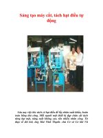
Máy cắt tuốt dây điện tự động (Automatic wire cutting and stripping machine)
Bạn đang xem bản rút gọn của tài liệu. Xem và tải ngay bản đầy đủ của tài liệu tại đây (1.98 MB, 41 trang )
PREFACE
In this demonstration, we will present the design, operating principle, and special
features of the wire stripper that we have developed. We will also explain how this wire
stripper can provide superior benefits over traditional methods and create advancements
in wire stripping technology.
We would like to sincerely thank the teachers for supporting our group in the
process of doing PBL4. We look forward to receiving comments from teachers after
reading the explanations.
1
ASSURE
I hereby commit that the content of the project "Automatic wire stripping
machine model" is the research work of our group. References and statistical data used
for research purposes of this product are completely honest and have clear origins. If
they are wrong, I will take full responsibility.
Students perform:
2
TABLE OF CONTENTS
PREFACE ......................................................................................................................1
ASSURE .........................................................................................................................2
TABLE OF CONTENTS ..............................................................................................3
INTRODUCTION .........................................................................................................6
CHAPTER 1: OVERVIEW OF METHODS OF CUTTING AND STRIPPING
ELECTRICAL WIRES ................................................................................................7
1.1 Popular methods of stripping and cutting electrical wires today: ..................7
1.1.1 Manual wire cutting and stripping method...................................................7
1.1.2 Automatic wire cutting and stripping ............................................................7
1.2 Introducing several types of wire stripping machines on the market: ...........8
1.2.1 KS-09I automatic wire stripping machine [1]...............................................8
1.2.2 Schleuniger EcoStrip 9380 automatic wire stripping machine [2] ..............9
1.3 Overview of wire stripping cutting machine:..................................................11
1.3.1 Main structure of electric wire cutting machine: .......................................11
1.3.1.1 Engine ....................................................................................................11
1.3.1.2 Roller .....................................................................................................11
1.3.1.3 Example of adjusting height and width..............................................12
1.3.1.4 Machine frame ......................................................................................12
1.3.1.5 Shaft coupling .......................................................................................13
1.3.1.6 Wire stripping and cutting pliers........................................................13
1.3.2 General operating principles of current wire stripping machines: ............14
CHAPTER 2: CALCULATION AND DESIGN OF MECHANICAL PARTS ....15
2.1 Design plan for rope pulling parts....................................................................15
2.1.1 Two-axis plan of co-rotation........................................................................15
2.1.1.1 Option 1: Use a pair of cylindrical gears............................................15
2.1.1.2 Option 2: Use two pairs of cylindrical gears ......................................15
2.1.2 Single-axis plan ............................................................................................16
2.1.2.1 Option 1: Direct drive ..........................................................................16
2.1.2.2 Option 2: Use flat belts and ladder belts ............................................16
2.2 Design of wire stripping cutting parts..............................................................17
2.2.1 Option 1: One fixed blade and one blade perform cutting movements......17
2.2.2 Option 2: Both blades perform the same cutting motion............................17
3
2.3 Transmission plan for the machine: ................................................................ 17
2.3.1 DC Motor......................................................................................................17
2.3.2 AC Motor (AC Motor)..................................................................................18
2.3.3 Stepping Motor ............................................................................................. 18
2.3.4 DC servo motor.............................................................................................18
2.4 Distance adjustment structure. ........................................................................ 18
2.4.1 Lead screw-nut transmission ....................................................................... 18
2.4.2 Ball screw-ball nut transmission ................................................................. 18
2.4.3 Adjusting screw ............................................................................................ 19
2.5 Choose a machine design option with the following technical parameters: 19
CHAPTER 3: CALCULATION AND DESIGN OF CONTROL PARTS ............ 20
3.1 Calculations for choosing an engine.................................................................20
3.1.1 Calculate the zipper and required clamping force: .................................... 20
3.1.2 Transmission design .................................................................................... 21
3.1.2.1 Choose engine ....................................................................................... 21
3.1.2.2 Calculate active axis ............................................................................. 21
3.1.2.3 Torque acting on the shaft...................................................................22
3.1.2.4 Calculate bending moments at dangerous points..............................23
3.1.2.5 Test shaft according to safety factor...................................................24
3.1.2.6 Select active shaft bearings..................................................................25
3.1.2.7 Select cutting motor ............................................................................. 26
3.1.3 Choose the controller and motor for the machine: .................................... 26
3.2 Components contained in the machine:...........................................................26
3.2.1 ARDUINO UNO R3.....................................................................................26
3.2.2 NEMA 17 STEPPER MOTOR....................................................................27
3.2.3 MG996R SERVO ......................................................................................... 28
3.2.4 LCD 16x2 AND I2C ..................................................................................... 29
3.2.5 TB6560 DRIVER CIRCUIT CONTROLS STEPPER MOTOR................30
3.3 Flowchart............................................................................................................31
3.4 AutoCad Design ................................................................................................. 32
3.5 Solidwords Design..............................................................................................33
3.5.1 Electronic drawing ....................................................................................... 33
3.5.2 Detailed drawing .......................................................................................... 34
3.5.3 AS - Build drawing.......................................................................................35
3.5.4 Exploded – view drawing ............................................................................. 36
4
3.5.5 3D model design ...........................................................................................36
CHAPTER 4: CONCLUSION ...................................................................................38
4.1 Results achieved .................................................................................................38
4.2 Restrictions .........................................................................................................38
REFERENCES ............................................................................................................39
5
INTRODUCTION
Today, industry and life are almost inseparable from electrical wires. In the
process of using electricity, we cannot avoid having to connect wires. And then you
need to remove enough insulation. Every day, at automobile factories and industries
related to electronic equipment, hundreds of sets of electrical wires of many different
types must be used. Most electrical wires are manufactured and packaged in rolls of a
certain size. When necessary, we need to cut the two ends of the wire at the appropriate
distance to serve the usage requirements of each different purpose. If you cut and strip
wire by hand, productivity is low, product quality is not guaranteed, causing a waste of
labor and production time. Therefore, the creation of automatic wire stripping machines
is very necessary to improve the accuracy and efficiency of wire stripping, helping to
ensure safety and reliability in the process of wire stripping, installation, and
maintenance of the system. system. power system. With the development of technology,
wire-cutting and stripping machines are increasingly improved in terms of features and
performance, meeting the increasing needs of the electrical and electronics industry.
6
CHAPTER 1: OVERVIEW OF METHODS OF CUTTING AND
STRIPPING ELECTRICAL WIRES
1.1 Popular methods of stripping and cutting electrical wires today:
1.1.1 Manual wire cutting and stripping method
The method of using specialized pliers to cut and strip electrical wires is a
common method for professional electricians. With this method, there are usually the
following steps:
Step 1: Place the wire you want to strip into the pliers. If you want the strip to be
longer, remove the red pin and push in more wire.
Step 2: Squeeze the pliers hard, the cutting blade will automatically separate the
wire sheath for you with the smaller wires (the gut of the wire above, for example).
Doing the same will not cause your wire to break. In addition, pliers can also be used to
cut electrical wires with very sharp and neat cuts.
Advantage:
Cost-effective, flexible and convenient, especially in small and simple jobs.
Disadvantage:
It is time-consuming, labor-intensive, error-prone, and ineffective on a large
scale. When working with complex wires or in large-scale applications, it is often
recommended to use automatic wire cutters and strippers to ensure the best performance
and safety.
Figure 1.1. Cutting and stripping electrical wires with pliers
1.1.2 Automatic wire cutting and stripping
The method of cutting and stripping electrical wires using a specialized machine
is known to be a commonly used method in industrial production. Machines are used to
remove the outer insulation layer of electrical wires. With this type of machine, cutting
both ends becomes faster, more accurate, and much easier. This method can
accommodate many different sizes, helping to save a lot of time and labor.
Advantages:
✓ Suitable for all sizes of electrical wires.
✓ The working speed of the wire stripper is very fast and highly accurate.
✓ The machine's wire stripping speed can be adjusted according to user
requirements.
7
✓ The blade of the wire stripper works very effectively thanks to rotating at high
speed.
✓ The length of the wire stripper layer can also be adjusted depending on
requirements.
✓ The working principle of the wire stripper is easy, safe, accurate, and extremely
durable.
✓ To meet user needs, there are 2 types of manual machines on the market:
handheld machines and fixed machines.
✓ The finished product of the wire stripper is both aesthetically pleasing and clean
without affecting the wire core.
Disadvantage:
• During the working process, the machine still makes noise.
• The cost of an electric wire stripper is still higher than other types of strippers.
Figure 1.2. Kodera Casting C377A and KS-W612 automatic wire stripping machines
1.2 Introducing several types of wire stripping machines on the market:
1.2.1 KS-09I automatic wire stripping machine [1]
Advantages:
✓ Performs half-threshing, full-threshing and middle-threshing functions.
✓ Supports 3-layer stripping, stripping length of each layer can be set differently.
✓ The machine is driven by 4 strong rollers, capable of increasing the maximum
capacity of 10.0mm2.
✓ The sturdy steel blade cuts well and effectively.
✓ The wire/cable conductor is designed to push up when stripping the wire end so
that the wire end stripping length can reach 70mm.
✓ The KS-09I electric wire stripper operates extremely easily, cutting to precise
positions, achieving high productivity and operating for a long time.
8
Figure 2: KS-09I automatic wire stripping machine
Wire size 0.1 – 10.0 mm2
Maximum cable diameter Φ10 mm
Cutting length 0-99999 mm
Threshing length Wire end 0-50mm, wire end 0-70mm
Accuracy ± (0.002mm × Stripping length)
Cutting precision ± (0.002mm × Cutting length)
Speed 3000-7000 pcs/hour
Display English LCD touch screen
Special functions Can strip 3 layers with different strip length for each layer
How to move 4 moving rollers
Blade material hard Vonfram steel
Wattage 220W
Electricity supply 220V/50Hz ; 110V/60Hz
Weight machine 36 kg
Size 390 x 350 x 255mm
1.2.2 Schleuniger EcoStrip 9380 automatic wire stripping machine [2]
Advantages:
✓ Three-in-one device: Schleuniger EcoStrip 9380 wire stripper with unique 3-
position design of the wire feeding system enhances customer customization and
can be set for normal mode, mode rolling or short mode - depending on
application.
✓ Easy to use: The Schleuniger EcoStrip 9380 is easily operated via the 5.7" color
touch screen and Schleuniger S.ON software.
9
✓ High precision.
✓ Cut length.
✓ Plucking Many layers.
Figure 1.3. Schleuniger EcoStrip 9380 automatic wire stripping machine
Maximum outer shell diameter 8 mm
Maximum wire cross-section 0.05 – 8 mm2
Cutter width 1 x 12 mm
Multilayer cable Yes
Maximum cutting length 1,000,000 mm
Left threshing length 46 mm
Right threshing length 152 mm
Option to cut wire short 46 mm (18 mm from cable sheath after stripping)
Connect
Standard: Ethernet for PC, USB Optional: SMI
Electricity supply (I/O‘s), Prefeeder, Wire marker (HS), Inkjet
Dimensions (L × W × H) printing, Stacker / Coiler
Weight 100 – 240VAC
435 x 397 x 360 mm
25 kg
10
1.3 Overview of wire stripping cutting machine:
1.3.1 Main structure of electric wire cutting machine:
Most types of automatic wire-stripping machines today have the same general
structure. As follows:
1.3.1.1 Engine
This motor is often attached to the belt shafts through the rotating shaft to transmit
motion to the rollers, conveyor belts, rollers, and pulleys.
Depending on the thinking of the designers/manufacturers, the motion
mechanism will be equipped with servo motors and stepper motors for control.
Figure 1.4. Step motor
Figure 1.5. Servo motor
1.3.1.2 Roller
A roller is an item used to guide, support, or transport products.
Commonly used roller types:
• Stainless steel roller
• Galvanized rollers.
• Rubber-coated roller
• Steel roller...
11
The load of each roller depends on the load of the product passing through it,
thereby determining the type of manufacturing material, roller tube thickness, whether
to use cast or welded tubes, and roller shaft parameters, use appropriate bearings.
These types of rollers often have high durability and simple structures including
ball bearings, roller shells, roller shafts, and some accompanying components. The roller
is installed on the shaft with a ball bearing, the outer ring of the ball bearing is tightly
attached to the roller, and the inner ring of the ball bearing is attached to the shaft.
The rollers mainly work on the outer surface, so their outer surface is machined
with a certain roughness so as not to affect the roller's working process.
Rubber roller V groove roller Cylindrical roller
Figure 1.6. Roller
1.3.1.3 Example of adjusting height and width
The screw is used to adjust the knife or roll opening.
Figure 1.7. Example of adjusting height and width
1.3.1.4 Machine frame
The chassis is the main structure of the device and is responsible for bearing the
load and supporting other structures and components. It secures the components of the
device along with other parts such as motors, batteries, controllers, and systems.
12
The chassis helps protect important components inside the device from impact
and damage from the external environment. It can be designed to withstand impacts and
forces from various road conditions, minimizing the risk of damage and ensuring the
safety of users and other critical components.
The chassis plays an important role in creating stability and balance for the
device. It is designed to ensure that gravity is distributed evenly and properly, helping
the user maintain stability and control the device with ease.
Figure 1.8. Machine frame
1.3.1.5 Shaft coupling
A screw coupling is a mechanical part that connects and transmits torque between
two moving component shafts, usually connecting 2 shafts or connecting from a motor
to a chain to operate a certain system.
Figure 1.9. Shaft coupling
1.3.1.6 Wire stripping and cutting pliers
There are many different types of wire cutters such as V blade, C blade, and flat
blade to serve different wire cutting purposes.
13
Or we can also use pliers to cut and strip the wire.
Wire cutting and stripping pliers Wire cutting and stripping blades
1.3.2 General operating principles of current wire stripping machines:
The wire taken from the wire supply part is threaded through the wire guide part
and inserted.
wire puller. The electric wire will be clamped tightly between two wire pulleys
with appropriate clamping force and adjusted by a screw-nut mechanism.
From the data the overall length of the wire as well as the length of the part that
needs to be stripped.
The operator provides information from the keyboard to the control software,
which will calculate the number of pulses needed to supply the stepper motor. The pulse
parameters will be sent to the processor, which will then provide pulses for the stepper
motor to operate. The stepper motor uses transmissions to make the pulley rotate, pulling
the wire to the required length.
In manual data entry mode, the user enters the following parameters:
• Cord length.
• Wire size.
• Length of plucking section at each end.
• Quantity to cut.
After the data has been validated (wire length to be stripped and line If the wire
is within the allowable range of the machine), press the START button to start the
machine. To ensure safety when using or fixing machine process errors, you can press
the STOP buttons to stop all machine processes. The cycle can also stop when the
number of products has been completed.
14
CHAPTER 2: CALCULATION AND DESIGN OF MECHANICAL
PARTS
2.1 Design plan for rope pulling parts
2.1.1 Two-axis plan of co-rotation
In order to drive the two axes to rotate together with the requirement that the
distance between the two axes can be adjusted, we can have options:
Use a cylindrical gear transmission.
2.1.1.1 Option 1: Use a pair of cylindrical gears
Figure 2.1. The system drives a pair of cylindrical gears
Advantage:
+ Simple structure.
Disadvantage:
+ The alignment height of the teeth decreases when we increase the axial
distance.
+ Narrow adjustment range. To increase the adjustment interval, we must use
gears with large modules.
2.1.1.2 Option 2: Use two pairs of cylindrical gears
15
Figure 2.2. The system drives two pairs of cylindrical gears
Advantage:
+ When the adjustment interval is small, the matching height is not changed much
+ Avoid having to use gears with large modules.
Disadvantage:
+ Increase manufacturing costs.
2.1.2 Single-axis plan
2.1.2.1 Option 1: Direct drive
Figure 2.3. Direct drive system
Advantage:
+ Simple structure, easy to arrange.
+ Turn price.
Disadvantage:
+ Difficult to adjust at low speeds.
2.1.2.2 Option 2: Use flat belts and ladder belts
Figure 2.4. Drive system using flat belt and ladder belt
16
Advantage:
+ Can drive between axes far apart.
+ Work quietly, without noise.
+ Thanks to the elastic properties of the belt, vibrations generated by loads are
avoided.
+ Change the effect on the structure.
+ Thanks to the slippage of the belt, it is recommended to prevent overload
occurring on the engine.
+ Simple structure and operation.
Disadvantage:
+ The size of the belt transmitter is large compared to other transmitters: chains,
gears.
+ The gear ratio changes due to slippage between the belt and the wheel.
+ The load acting on the shaft and drive is large (usually 2-3 times higher than
that of the transmission
+ gear) due to the initial belt tension.
+ Low belt transmission service life
2.2 Design of wire stripping cutting parts
2.2.1 Option 1: One fixed blade and one blade perform cutting movements
In this embodiment, one blade is held in place. The other blade is linked into a
cluster that can move translationally. Translational motion is formed by a mechanism
that turns rotation into translational motion, such as nut screw mechanism, tooth-gear
rod ... When the stepper motor rotates, through the tooth belt transmission, the
translational movement blade performs cutting, stripping the shell.
Advantage:
+ Simple structure, easy to process and assemble.
+ Low cost.
Disadvantage:
+ The cutting force is uneven, but with soft materials, the effect of this factor
negligible.
2.2.2 Option 2: Both blades perform the same cutting motion
In this case, similar to option 1, here we use 1 shaft connection and in the tamarind screw
transmission, to say that 2 screws are directed in opposite directions to each other. The
translational and opposite movements of the 2 blades are formed by a mechanism that
converts rotation into translational motion, such as a nut screw mechanism, due to
opposite teeth.
Advantage:
+ Simple structure, easy to process and assemble.
+ Low cost.
Disadvantage:
+ Uniform cutting force.
2.3 Transmission plan for the machine:
2.3.1 DC Motor
Advantage:
Large starting torque, easy-to-control speed, and direction, low price.
Disadvantage:
17
• Narrow control speed range.
• Must have its power circuit.
2.3.2 AC Motor (AC Motor)
Advantage:
✓ Powered directly from the AC grid.
✓ Diverse and very rich in types, low price.
Disadvantage:
• There must be an isolation circuit between the control part and the actuator to
ensure safety and a small starting torque.
• Complicated speed control circuit, often using an inverter.
2.3.3 Stepping Motor
Advantage:
✓ Accurate position and speed control, no feedback circuit required.
✓ Easy to control speed and direction.
✓ Cheap price.
Disadvantage:
• Small torque.
• There is no feedback so it may cause errors.
2.3.4 DC servo motor
Advantage:
✓ Torque on control shaft.
✓ Precise speed control thanks to the feedback system.
Disadvantage:
• The price is expensive.
• Do not work in open circuit mode.
• Difficult to control.
2.4 Distance adjustment structure.
2.4.1 Lead screw-nut transmission
Advantage:
Cheap price, easy to manufacture.
Disadvantage:
• High contact stress, high friction, low efficiency.
• It is difficult to eliminate the gap between the lead screw and the nut.
2.4.2 Ball screw-ball nut transmission
Advantage:
✓ The structure to eliminate gaps and create initial tension is available.
✓ Small friction, high performance.
Disadvantage:
High cost, difficult to manufacture.
18
2.4.3 Adjusting screw
Advantage:
Cheap price, easy to manufacture, simple customization and adjustment.
Disadvantage:
Large gap.
2.5 Choose a machine design option with the following technical parameters:
From the characteristics and requirements of the project, we have come up with
the following options for our cutting machine model:
❖ The design option for the wire drawing unit is to choose a direct-drive rotary shaft
type.
❖ The design plan for the wire stripping cutting unit selects one fixed blade and one
blade to perform the cutting motion.
❖ For the design of the transmission part in this project, we choose to use a stepper
motor.
❖ Design plan for the distance adjustment mechanism with not too high
requirements of the model, we choose the adjustment mechanism with adjusting
screw.
19
CHAPTER 3: CALCULATION AND DESIGN OF CONTROL PARTS
Function: As mentioned above, the central control circuit has the function of
signal control and mechanical control, controlling the motor to rotate smoothly and
paradoxically so that the machine can pull the wire forward and backward. again,
rhythmically.
➢ Input: is a command to input signals from the keyboard.
➢ Output: are the pulses given to the circuit control facility.
In this program, we will focus on calculations, appropriate equipment, and design
drawings for control systems.
3.1 Calculations for choosing an engine
We choose a wire with a length of 50m, and a cut wire with a defined width of
10mm2. Look up standard TCVN 6610-3- type of conductor that cannot be pressed
tightly (NC). We have a mass of wire of 116.3 Kg/km.
50m of electric wire has a mass of:
• The total mass of the coil (including the wire and the drum) 6 (Kg)
• Total coil weight:
50 ∗ 116,3
m = 1000 = 5,82(kg)
• The total weight of the coil (including wire and drum): 6 (Kg) => P = 60(N)
Calculate the energy in the drive
• The friction coefficient in transmission f = 0.15
Fms = P ∗ f = 9(N)
3.1.1 Calculate the zipper and required clamping force:
• Force Required to pull the rope:
Fkd = Fms. k1.k2
In there:
k1 is the experimental coefficient of the wire-pulling part. Get k1 = 1,2
k2 is the actual coefficient under load. Get k2 = 1,2
Fkd = 9 × 1,2 × 1,2 = 12,96(N)
• To make the rope pulley workable, the compression load Fn is:
In there: K × Fkd
Fn = f
K: is the contact safety factor.
For power transmitters, K = 1.2÷1.5 For transmitters in measuring instruments,
K = 3÷5.
f: is the friction coefficient between the pulley surfaces.
• For rubber surface pairs:
Rubber: f = 1,16
• Substituting into the formula we have:
20