HIGH PERFORMANCE MICROPROCESSOR-BASED TEMPERATUREHUMIDITY RECORDER WITH REMOTE SENSOR
Bạn đang xem bản rút gọn của tài liệu. Xem và tải ngay bản đầy đủ của tài liệu tại đây (1.01 MB, 64 trang )
9 3 User’s Guide
8 4
765
T H35 T2
E
M
P
E
R
A
T
U
R
E
H
U
M
I
D
I
T
Y
RH
7 4 °F °C
Shop online at
omega.com
e-mail:
For latest product manuals:
omegamanual.info
CT485B-110V-G-AL,
CT485B-220V-G-AL,
CT485B-110V-W-AL,
CT485B-220V-W-AL
High Performance
Microprocessor-Based Temperature
and Humidity Recorder
OMEGAnet® Online Service Internet e-mail
omega.com
U.S.A.: Servicing North America:
ISO 9001 Certified One Omega Drive, P.O. Box 4047
Stamford, CT 06907-0047
Canada: TEL: (203) 359-1660
FAX: (203) 359-7700
e-mail:
976 Bergar
Laval (Quebec) H7L 5A1, Canada
TEL: (514) 856-6928
FAX: (514) 856-6886
e-mail:
For immediate technical or application assistance:
U.S.A. and Canada: Sales Service: 1-800-826-6342/1-800-TC-OMEGA®
Customer Service: 1-800-622-2378/1-800-622-BEST®
Engineering Service: 1-800-872-9436/1-800-USA-WHEN®
Mexico: En Espan˜ ol: (001) 203-359-7803
e-mail:
FAX: (001) 203-359-7807
Czech Republic: Servicing Europe:
Frystatska 184, 733 01 Karviná, Czech Republic
TEL: +420 (0)59 6311899
FAX: +420 (0)59 6311114
Germany/Austria: Toll Free: 0800-1-66342
e-mail:
United Kingdom:
Daimlerstrasse 26, D-75392 Deckenpfronn, Germany
ISO 9002 Certified TEL: +49 (0)7056 9398-0
FAX: +49 (0)7056 9398-29
Toll Free in Germany: 0800 639 7678
e-mail:
One Omega Drive, River Bend Technology Centre
Northbank, Irlam, Manchester
M44 5BD United Kingdom
TEL: +44 (0)161 777 6611
FAX: +44 (0)161 777 6622
Toll Free in United Kingdom: 0800-488-488
e-mail:
It is the policy of OMEGA Engineering, Inc. to comply with all worldwide safety and EMC/EMI
regulations that apply. OMEGA is constantly pursuing certification of its products to the European New
Approach Directives. OMEGA will add the CE mark to every appropriate device upon certification.
The information contained in this document is believed to be correct, but OMEGA accepts no liability for any
errors it contains, and reserves the right to alter specifications without notice.
WARNING: These products are not designed for use in, and should not be used for, human applications.
TABLE OF High Performance Microprocessor-Based
CONTENTS Temperature/Humidity Recorder with Remote Sensor
Page
Chapter 1 Introduction ....................................................................... 1-1
1.1 Parts of the Recorder - Front and Side Views .................................. 1-2
1.2 Parts of the Recorder - Rear View ...................................................... 1-4
Chapter 2 Setting Up the Recorder ..................................................... 2-1
2.1 Placing the Recorder on the Bench Top ............................................ 2-1
2.2 Mounting the Recorder on the Wall .................................................. 2-3
2.3 Using Batteries ...................................................................................... 2-4
2.3.1 Installing Batteries ................................................................... 2-4
2.3.2 Connecting ac power .............................................................. 2-5
2.4 Installing the Chart Paper ................................................................... 2-6
2.5 Installing and Removing Pens ........................................................... 2-8
2.5.1 Installing the Pens ................................................................... 2-8
2.5.2 Removing the Pens ................................................................ 2-10
2.6 Installing the Temperature/Humidity Sensor ............................... 2-11
2.6.1 Using the Short Cable ........................................................... 2-11
2.6.2 Using the Remote Sensor Cable .......................................... 2-12
2.6.3 Using the Sensor Clip ........................................................... 2-13
Chapter 3 Powering Up the Recorder ................................................. 3-1
3.1 Turning on the Recorder ..................................................................... 3-1
3.2 Recording the Code Numbers ............................................................ 3-1
3.3 Comparing Code Numbers ................................................................ 3-2
3.4 Final Display Mode .............................................................................. 3-3
Chapter 4 Alarm Operation ............................................................... 4-1
4.1 Alarm Description ............................................................................... 4-1
4.2 Checking Alarm Limits ....................................................................... 4-1
4.3 Unlocking/Locking the Control Panel Door ................................... 4-2
4.3.1 Unlocking the Control Panel Door ....................................... 4-2
4.3.2 Locking the Control Panel Door ........................................... 4-2
4.4 Setting/Changing Alarm Limits ........................................................ 4-3
4.5 Turning the Alarm Off ......................................................................... 4-4
4.6 Disabling the Alarm ............................................................................ 4-5
Chapter 5 Calibrating the Recorder .................................................... 5-1
5.1 Factory Calibration Information ........................................................ 5-1
5.2 Changing Calibration Codes .............................................................. 5-1
5.3 Calibrating Humidity Readings ......................................................... 5-4
5.3.1 Humidity Calibration at 33% Humidity .............................. 5-6
5.3.2 Humidity Calibration at 75% Humidity .............................. 5-7
5.4 Calibrating Temperature Readings .................................................... 5-8
i
TABLE OF High Performance Microprocessor-Based
CONTENTS Temperature/Humidity Recorder with Remote Sensor
Page
Chapter 6 Using the Cal-Lock Kit ........................................................ 6-1
Chapter 7 Using the Voltage Input Adapter (Optional) ........................ 7-1
Chapter 8 Maintaining the Recorder .................................................. 8-1
8.1 General Considerations ....................................................................... 8-1
8.2 Light Bulb, Display Backlighting and Push Button Information .... 8-2
8.3 Case Care................................................................................................ 8-3
8.4 Storage of Chart Paper ........................................................................ 8-3
8.5 Power Failure Mode (Chart Paper Indication) ................................ 8-3
Chapter 9 Troubleshooting the Recorder ............................................ 9-1
Chapter 10 Technical Details ............................................................ 10-1
Chapter
10.1 Sensors and Measurement ................................................................ 10-1
10.2 Pen Arm Drive .................................................................................... 10-1
10.3 Chart Paper Drive Mechanism ......................................................... 10-2
10.4 Power Supply Supervision ............................................................... 10-2
11 Specifications ................................................................ 11-1
Chapter 12 Sensor Design for CE Conformity .....................................12-1
Index ....................................................................................................... I
ii
1 Introduction
This Electronic Temperature and Humidity Chart Recorder with Remote Sensor
is an advanced micro computer controlled measuring and recording instrument.
The recorder affords precision rapid response, memory and display of peak
readings, remote sensing, recording flexibility and simplicity of operation. This
compact, portable instrument offers advanced features previously unavailable in
its price range.
Features include:
• Continuous Update of Ambient °C or °F Temperature and Relative
Humidity
• Rapid Response to Changes in Ambient Temperature and Humidity
• Remote Mount Sensor
• Digital Plots in 1° or 1% Increments
• Memory and Display of Peak Readings
• 1, 7 or 32 Day Charts
• Battery or ac Power Operation With Automatic Battery Power Backup
• Chart Indication for ac Power Failure/ac Power Return
• Audible Alarm with Relay Contact
• Low Battery Indicator
• Portable
• Wall Mount or Benchtop Mount
• Optional Analog Voltage Input Adapter to record an external 20 to 1200mV
dc signal using the temperature pen
• Chart Lighting and display backlighting with use of ac adaptor
• Control Panel Lock
• Decorative Foot Cover for wall mounting
These features provide precise documentation, flexibility in application and ease
of use, all made possible through the incorporation of advanced electronics.
1-1
1 Introduction
1.1 Parts of the Recorder - Front and Side Views
13
15 T 2
1 E 20
M
15 P H35 T2 14
E
R 3
A
T 4 16
U
R 2
E
H
U
M
I
D
I
T
Y
5
I °C HIGH SET LOW RH 6
1
7 4 °F °C 12
17 7 11
7 18 18
8 0 °F 32
9 CHART TYPE
ALARM
PWR
10 19
FRONT VIEW SIDE VIEW
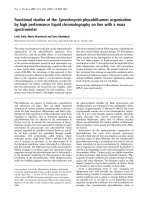
Figure 1-1. Front and Side Views of the Recorder
Item Description Function
1 Chart Paper Knob (magnetic) Holds chart paper in place.
2 Light Bulbs
Lights up the paper in a dark room. Note that the bulbs function only
3 Pen Cap Posts when the recorder is powered by the 9Vdc adapter.
4 Time Set Arrow
5 Chart Paper (double sided) Holds the loose pen caps.
Helps align the time on the new chart paper with the actual time.
Charts are available for 1, 7, and 32 day recording times in both °C
and °F. See the inside back cover for a detailed list of paper
available.
1-2
Introduction 1
Item Description Function
Allows the unit to be powered from ac power using the ac adaptor
6 ac Power Jack (110Vac stepped down to 9Vdc) supplied.
7 Power Switch Turns unit ON (|) or OFF (O).
8 °C/°F Mode Switch
Selects °C or °F chart operation. Note the following :
9 1/7/32 Day Mode Switch When switching from °C to °F, ONLY the humidity pen will move. The
humidity zero point and scaling are different on C° and °F paper, causing the
10 Alarm Display Buttons humidity pen to move when switching from °C to °F. The temperature zero
(HIGH, SET, LOW) point and scaling are the same on °C and °F paper (only the units change).
Therefore, the temperature pen will not move.
11 LCD Display
Selects chart type, 1, 7, or 32 day operation.
12 Display Selection Switch
These buttons are accessible behind the control panel door.
13 Temperature/Humidity Sensor High and Low buttons:
1. Selects and changes calibration codes.
14 Sensor Holder (clip) 2. Chooses the high/low alarm limit (for either °F, °C or %RH).
15 Pen Arm and Holder (2 each) 3. Selects and changes the alarm limits.
16 Latch Button 4. Checks alarm limits in operating mode.
17 Control Panel Door Lock 5. Low button only: when pressed during power up, disables the
18 Decorative Foot Cover
alarm function.
19 Control Panel Door
Set button:
20 Light Bulb/Display Backlighting 1. Activates calibration mode when pressed during power up.
Push Button 2. Enters calibration codes in memory.
3. Activates alarm limits.
4. Enters alarm limits in memory.
5. Disables the sounding of the alarm (and activation of the relay)
for 10 seconds.
Displays temperature and humidity values (depending on the setting of
Display Selection Switch.
Allows the user to select display of the current relative humidity, or
ambient temperature in either °C or °F. Refer also to item #10.
Houses the electronic sensors which measure ambient temperature and
relative humidity.
Holds the temperature/humidity sensor to the side of the recorder.
Holds and moves the temperature and humidity pens.
Releases and secures the recorder’s door.
Locks or unlocks the control panel door.
Stays in place for wall-mounting the recorder. The cover must be
removed for upright bench-top use (otherwise the recorder topples over)!
Covers the alarm display buttons (High, Set, and Low), power switch,
1/7/32 day mode switch, and °F/°C mode switch.
Turns the light bulbs and LCD Backlighting on and off
1-3
1 Introduction
1.2 Parts of the Recorder - Rear View
21
22
H35 T2
23
24
25
Item Description Foot Cover Removed
21 “Keyhole” Slot Mounting Holes Figure 1-2. Rear View
22 Carrying Slot
23 Product Label Function
24 Alarm/Relay Contacts
Allows the recorder to be mounted on the wall.
25 Battery Compartment Allows the user to carry the recorder conveniently.
Product information label.
Allows the user to hook up an external, dry contact alarm to the
recorder.
Holds 4 “D” size batteries which provide power if the ac adaptor is
not used, or provide power backup in case of ac power failure.
1-4
2 Setting Up the Recorder
Now that you have learned about the different parts of the recorder, you can set
it up.
Determine whether you want the recorder wall mounted or sitting on a bench
top.
2.1 Placing the Recorder on the Bench Top
Figure 2-1 shows the removal of the decorative foot cover.
1. Place the recorder on its back (so it is face up).
2. Remove the clip-on foot cover by lifting up on the cover and releasing it from
the stabilizing arm at the bottom of the recorder. This exposes the rubber feet
and stabilizing arm. The rubber feet protect the bench top surface.
! CAUTION
DO NOT ATTEMPT TO SET THE RECORDER UPRIGHT ON
THE BENCH WHEN THE CLIP-ON FOOT COVER IS IN
PLACE. THE RECORDER WILL TOPPLE OVER.
Cutaway View
Clip
Figure 2-1. Foot Cover Removal
2-1
2 Setting Up the Recorder
3. Swing out the stabilizing arm and extend it towards you. Figure 2-2 shows
how to swing out the stabilizing arm. Make sure the slot in the stabilizing arm
extends out the rear of the recorder.
Swing
Figure 2-2. Swiveling Stabilizing Arm
NOTE
When the recorder is in normal operating position (the door
is closed and the control panel door is closed), the stabilizing
arm should be pushed to middle position (the bumps on the
arm will click in place under the recorder). Refer to Figure
2-3a.
Before opening the chart door, pull the stabilizing arm out to
its full extension position to provide full stability. Refer to
Figure 2-3b. After closing the door, return the arm to its
middle position. Refer to Figure 2-3a.
Note that the arm extends towards the front or rear of the
case. If the unit is placed on a bench top snug against the
wall, extend the stabilizing arm fully to the front of the unit.
Refer to Figure 2-3b.
Figure 2-3a. Stabilizing Arm use Figure 2-3b. Stabilizing Arm in Extended
for Bench Top Use (normal position) Position (position when you open door)
2-2
Setting Up the Recorder 2
2.2 Mounting the Recorder on the Wall
To mount the recorder on the wall, first locate the wall mounting holes using the
template provided in the wall mounting kit. Leave the decorative foot cover
(Figure 1-1, item #18) in place*. After drilling the holes, insert the wall anchors
and put in the screws, leaving 1⁄8 inch (3 mm) between the screw heads and the
wall. Hang the recorder by positioning the two (2) “keyholes” in the rear cover
over the screw heads.
NOTE
The ac adaptor has a 6 foot (2 meter) cable.
* If the decorative foot cover is not in place, go through the following steps to
reinstall the cover (if desired):
1. Place the recorder on the table (so it is front face up).
2. Roughly position the foot cover so the clips are in line with the stabilizing
arm. Gently “stretch” the clips out and position over the arm as shown in
Figure 2-4a.
3. Once the clips are in place, gently slide down until the foot cover is even
with the front of the recorder as shown in Figure 2-4b.
T H35 T2
E
M Cutaway View
P Clip
E
R
A
T
U
R
E
H
U
M
I
D
I
T
Y
RH Figure 2-4b. Installing the Foot Cover (Side View)
°C 2-3
°F
Clips
Figure 2-4a. Installing the Foot Cover
(Top View)
2 Setting Up the Recorder
2.3 Using Batteries
The recorder operates on either four “D” size batteries or on ac power. 110Vac
and 220Vac adaptors are available.
NOTE
In the event of ac power failure, the unit will switch over to
battery power automatically.
Keep a fresh set of batteries in the unit in case of power
outage, when it will be especially important to have a record
of ambient temperature and humidity.
2.3.1 Installing Batteries
You may power the recorder with four “D” size batteries. For adequate
performance and battery life, use alkaline batteries. The recorder operates full
time on battery power alone for up to one month when using fresh alkaline
batteries. When replacing batteries, we recommend that you use Duracell
MN1300 “D” size batteries for long life and for best performance at low
temperatures.
To install the batteries (refer to Figure 2-5):
+ –+ –+ –+ –
Bench Top Set-Up Battery Orientation
To Open
Figure 2-5. Battery Compartment and Battery Orientation
2-4
Setting Up the Recorder 2
1. Open the control panel door.
2. Turn the power switch to the OFF or “O” position.
3. Place the recorder on a soft surface front face down. Locate the battery
compartment at the bottom.
4. Open the battery compartment door by pressing down firmly on the tabs
located along the top edge.
5. Remove the battery door.
6. Install the batteries, oriented as shown in Figure 2-5, in the battery
compartment.
7. To replace the battery door, first place the bottom edge of the door into the
positioning slots in the compartment.
8. Push down on the door to snap the tabs in place.
The recorder continuously monitors the battery voltage. A “LO BAT”
indication in the upper left-hand corner of the main LCD (refer to Figure 2-6)
indicates that only one to two weeks of reliable battery operation remain, and
that the batteries need replacing within this time frame. Also, if the unit is
operating under battery power and the battery voltage is too low to permit
reliable operation, the system shuts down and displays “---” in the LCD. The
system may be restarted by changing the batteries or by the re-initiation of ac
power. If ac power fails, the circuitry will attempt to automatically switch to
battery backup. If viable battery power is available, the system will operate on
battery power until the batteries fail or ac power returns. When ac power
returns, the recorder will automatically reset itself (refer to Section 8.5).
LO BAT RH
°C
°F
System Shut-Down
Figure 2-6. Battery Warnings
2.3.2 Connecting ac Power
The recorder can be ac powered using the 9Vdc, 1Amp ac adaptor supplied. The
ac power jack is located on the right side of the unit (refer to Figure 1-1, item #6.).
Make sure the power switch on the control panel (refer to Figure 1-1, item #7) is
in the OFF or “O” position when plugging in the ac adaptor. The adaptor cable
is 6 feet (2 meters) long.
2-5
2 Setting Up the Recorder
2.4 Installing the Chart Paper
The recorder accepts six different types of chart paper. Charts are available for
1, 7 and 32 day recording times in both Fahrenheit or Celsius versions. Although
chart paper replacing is very simple, you must take care to set the appropriate
front panel switches for the paper being used. Set the chart type and °C/°F
switches (refer to Figure 2-7) to the following positions for these six (6) modes of
operation.
Chart Type Switch (Days) C/F Switch Paper Type
1 F 1-day, Fahrenheit paper
1 C 1-day, Celsius paper
7 F 7-day, Fahrenheit paper
7 C 7-day, Celsius paper
32 F 32-day, Fahrenheit paper
32 C 32-day, Celsius paper
HIGH SET LOW
I °C 1 RH
0 °F 7 °C
32 °F
ALARM
PWR CHART TYPE
Figure 2-7. Chart Switches
You may obtain specialized paper as well. Refer to the inside back cover for the
complete list.
2-6
Setting Up the Recorder 2
To change the chart paper:
1a. Table Mounted Recorder:
To balance the recorder, fully extend the stabilizing arm at the bottom of the
recorder. Refer to Figure 2-8. Continue to Step 2.
Figure 2-8. Stabilizing Arm Fully Extended
1b. Wall Mounted Recorder:
You can also leave the recorder on the wall if it is easily accessible.
2. Open the door and hold it open with left hand.
3. Remove the magnetic chart paper knob (Figure 2-9, item #2) and any used
chart paper.
4. Place the new chart paper (Figure 2-9, item #1) on the spindle and rotate it
until the current time on the chart paper is aligned with the time arrow on the
chart base of the recorder. See Figure 2-9 detail.
5. When the chart paper is correctly oriented, replace the magnetic knob
(Figure 2-9, item #2), being careful not to alter the position of the chart paper.
6. Make sure that the “Chart Type” switch, located behind the control panel door,
is in the correct position relative to the chart paper used.
NOTE
If the switch is in the wrong position, the chart paper will not
rotate at the correct speed causing the chart time not to be
synchronized with the current time.
2-7
2 Setting Up the Recorder
1
H35 T2 2
HIGH SET LOW
1 °C 1 RH
0 °F 7 °C
32 °F
ALARM
PWR CHART TYPE
7 PM ੭ 7:00 PM
NOTE: ROTATE CHART PAPER
UNTIL PRESENT TIME
LINES UP WITH ARROW.
Figure 2-9. Changing Chart Paper and Setting the Time
2.5 Installing and Removing Pens
2.5.1 Installing the Pens
The recorder uses two different colored pens to record information. The red
(upper) pen records temperature. The blue (lower) pen records relative
humidity. Pen life varies with use and climate. Under normal operating
conditions, pens last at least one month. We recommend that you install a fresh
set of pens after every month of use.
To install pens:
1. Make sure the power switch on the front panel is in the OFF or “O” position.
The front panel is located under the control panel door. The recorder door
should be closed too.
NOTE
The control panel door opens easily by gently gripping the
recessed area at the right side and slowly pulling down.
2. Examine the location of the pen arms through the window in the recorder door.
a. If the pen arms are offset as shown in Figure 2-10, continue to Step 3:
Temperature Temperature
Pen Pen
OR Humidity
Pen
Humidity
Pen
Figure 2-10. Offset Alignment of Pens (for ease of pen installation)
2-8
Setting Up the Recorder 2
b. If the pen arms are vertically aligned as shown in Figure 2-11, do the
following and then proceed to Step 3.
Temperature
Pen
Humidity
Pen
Figure 2-11. Vertical Alignment of Pens (pens can’t be inserted)
(The pen arms must be offset sufficiently to allow for clearance before insertion
or removal is attempted. The pens must be moved electrically.)
• Make sure the recorder door is closed and a piece of chart paper is
installed on the spindle on the chart base.
• Turn the unit back on by moving the power switch to “|” and wait for
the pens to be far enough apart to remove a used pen one at a time or
to insert a new pen one at a time.
CAUTION
! DO NOT ATTEMPT TO OFFSET THE PENS
MANUALLY (BY HAND). THE DRIVE MECHANISM
COULD BE DAMAGED. DO NOT ATTEMPT TO
CHANGE THE PENS WHILE THEY ARE IN MOTION.
• Turn off the unit (PWR switch position in “O” position) to stop the pen
movement.
3. Open the recorder door by applying downward pressure on the latch button
(refer to Figure 1-1, item #16).
4. Remove the pens from the package and the cap from each pen.
We recommend that you put the pen caps on special posts located on the chart
base of the recorder near the light bulbs. Figure 2-12 shows the location of the
posts.
T H35 T2
E
M Pen Cap Posts
P
E
R
A
T
U
R
E
H
U
M
I
D
I
T
Y
Figure 2-12. Post Location for Pen Caps
2-9
2 Setting Up the Recorder
5. Insert the blue pen fully into the lower (humidity) holder and the red pen fully
into the upper (temperature) holder.
If you installed the pens correctly, you will hear a click as they position
themselves in the holders. Figure 2-13 shows how to insert the pens.
6. Close the recorder door.
Figure 2-13. Pen Installation
2.5.2 Removing the Pens
1. Check to see that the pens are offset as shown in Figure 2-10. Otherwise, you
can damage the arm and drive mechanism if you try to remove them.
CAUTION
! DO NOT ATTEMPT TO OFFSET THE PENS MANUALLY (BY
HAND). THE DRIVE MECHANISM COULD BE DAMAGED.
DO NOT ATTEMPT TO CHANGE THE PENS WHILE THEY
ARE IN MOTION.
2. Perform Step 2b in Section 2.5.1 to offset the pens.
3. With a screwdriver in one hand, push on the rectangular area of the pen
shown in Figure 2-14. Using the other hand, release the pen from the spring
clip attached to the pen holder.
Figure 2-14. Pen Removal
2-10
Setting Up the Recorder 2
4. At the same time, slide the pen out from the pen holder.
5. Install new pens following Section 2.5.1, Steps 3 through 6.
2.6 Installing the Temperature/Humidity Sensor
The temperature/humidity sensor can either be directly attached to the recorder
using its own attached short cable or be extended by using the 6 ft remote sensor
cable.
2.6.1 Using the Short Cable
1. Place the handle part of the sensor in to the sensor clip on the side of the
recorder as shown in Figure 2-15.
T H35 T2
E
M H35 T2
P
E H35 T2
R
A
T
U
R
E
H
U
M
I
D
I
T
Y
SIDE VIEW
RH
°C
°F
Figure 2-15. Attaching the Sensor (left picture), Correct Position (center),
Incorrect Position (right)
2. Install the connector into the socket at the side of the recorder. Make sure the
sensor cable is untwisted.
3. Slide the sensor up so that the sensor vents are well above the top of the case.
Refer to the center picture in Figure 2-15.
2-11
2 Setting Up the Recorder
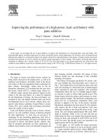
2.6.2 Using the Remote Sensor Cable
1. Connect the end of the cable with the arrow to the short cable on the sensor.
Line up the two arrows as shown in Figure 2-16 before mating the two cables.
2. Connect the other end of the remote sensor cable (without the arrow) to the
socket at the side of the recorder.
T
E
M
P
E
R
A
T
U
R
E
H35 T2
RH
°C
°F
Figure 2-16. Using the Remote Sensor Cable
NOTE
For accurate temperature and humidity readings, only one
length of remote sensor cable may be used.
2-12