9 distance measuring equipment
Bạn đang xem bản rút gọn của tài liệu. Xem và tải ngay bản đầy đủ của tài liệu tại đây (1.75 MB, 51 trang )
1/9/2021 DISTANCE MEASURING EQUIPMENT | McGraw-Hill Education - Access Engineering
( (/)
Search AccessEngineering here...
Within this book
Browse AccessEngineering content by... Show less
Course
Subject Industry
Books (/search?query=&f%5B0%5D=content_type%3ABooks&f%5B1%5D=book_component%3ATitles) Other ()
Airport Ground Navigation
Systems
Dr. Arjun Singh
(/content/bookI/S9B7N8:090778000770047405494)59
Publication Date & Copyright: 2012 McGraw-Hill Education Private Lim-
ited
Show more
Table of Contents Figures (20) Tables (1)
View: Table of Contents Tools
9. DISTANCE MEASURING
EQUIPMENT
Introduction
DME measures the distance with respect to a ground transponder beacon by
the length of time elapsing between the transmission of a pulse 'interrogation'
signal from the aircraft and the reception of a similar pulse 'reply' from the
beacon. Traffic 'To and From' several beacons is channeled by a combination
of frequency and pulse-pair coding wherein each signal consists of a pulse-pair
of distinctive spacing. The aircraft component is referred to as interrogator and
the ground component as transponder. Circuits are designed in such a way
that they recognize only pulse-pairs whose leading edges are separated by the
proper time interval (of the order of 10 to 25 μs). Data is presented of the ex-
tent to such pulse-pairs can be used to permit several transponder beacons,
within overlapping service areas, to operate on common interrogation and
common reply frequencies when serving a multiplicity of interrogator respon-
sors of the automatic searching and tracking type.
The DME should provide for continuous and accurate indication in the cockpit
of the slant range distance of an equipped aircraft from an equipped ground
reference point. The system comprise of two basic components one fitted in
the aircraft, the other installed on the ground. In operation interrogators will in-
terrogate transponders which in turn transmit the replies synchronous with in-
terrogating pulses thereby providing means for accurate measurement of dis-
tance. Capability should exist for displaying information relating to distance
1/51
1/9/2021 DISTANCE MEASURING EQUIPMENT | McGraw-Hill Education - Access Engineering
and rate of change of distance. While the DME operates with only 52 channels,
the experience obtained with this equipment has been used to standardize in-
ternationally the same channeling method to obtain 100 channels.
9.1. HISTORICAL BACKGROUND
The introduction of intercept equipment on-board aircraft early in the Second
World War brought into use for the first time, the extensive application of
equipment that would indicate directly the distance to a point. It was not long
until it was determined that a beacon (transponder) located on the ground
could be used in conjunction with the early airborne radar to furnish the valu-
able navigational information. Transponder beacons were necessary for use in
conjunction with early airborne radar because the very high frequency em-
ployed for intercept purpose, did not permit distance reading at low altitudes
purely through target reflections. The usefulness of distance information fur-
nished by the combination of airborne radar interrogators and ground
transponders led to war time experience for development of distance-direction
system, It was probably the Engineers of the 'WRIGHT FIELD' Laboratories of
the United States Air Force, who foresaw the advantages of a distance direc-
tion system (Polar Navigational System) which frame of the reference is con-
sidered to be the earth. Such a system, they reasoned, will permit to generate
unlimited numbers of fixed flight paths. This group had urged the development
of Distance Measuring Equipment (DME) that could be used in conjunction
with VOR that later on was developed by Civil Aeronautical Administration
(CAA).
In 1949, the ICAO recognized UHF DME in its standards and recommended
practices with the following paragraph appearing under the recommendation
for short distance aids.
'…. It is intended that UHF DME (distance measuring equipment) will become a
basic component of VOR at the earliest date practicable, to be added to all VOR
which has been installed before that date….'
The ICAO document referred to includes a development specification for a
DME operating frequency in the 960 to 1215 MHz range.
9.2. PRINCIPLE OF DME SYSTEM
The basic principle of the distance measuring system is explained with help of
Fig. 9.1. The system consists of airborne equipment known as interrogator-re-
sponder, commonly shortened to interrogator, and ground equipment referred
to as transponder or beacon, but more appropriately called transponder. The
cycle of the events that results in furnishing of an accurate indication of dis-
tance, begins with the modulator in the interrogator equipment. In the modu-
lator, pulses are generated of few microseconds' lengths. The rate at which
these pulses are generated is rather low and seldom exceeds 150 per seconds.
These pulses are generated in pairs. The output of the modulator is applied to
a radio frequency generator that incorporates provisions for operating on num-
ber of different radio frequency channels. The output of the radio frequency
generator, which occurs at a frequency f1, is connected to an antenna. This an-
tenna is common to the airborne receiver, but pulses do not disturb it since this
receiver operates on a frequency fT that is appreciably different from f1. It is ne-
cessary to connect the input circuit of the receiver to the antenna by means of
an efficient filter usually known as a pre-selector.
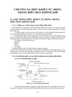
Figure 9.1 Block diagram of an interrogator-responder and a ground
transponder.
2/51
1/9/2021 DISTANCE MEASURING EQUIPMENT | McGraw-Hill Education - Access Engineering
Open in new tab (/mhe-lookup/tab-link/ch09fig01/6076385)
Share (/#copy_link)
On leaving the aircraft antenna, the pulses travel to the ground, where the
transponder antenna picks them up. The transponder antenna has non-direc-
tional characteristics in the horizontal plane, but has a directional pattern in the
vertical plane. The antenna is connected to a receiver pre-selector and then to
a receiver. After detection, the signals are amplified by a video amplifier and
passed through a delay network having a calibrated period and it is passed to a
modulator. The modulator amplifies the pulses from the receiver and im-
presses them on a transmitter operating at a carrier frequency 'fT'. From the
transmitter, the signals are connected to the same antenna used for receiver as
well. From the ground antenna, the signals are transmitted to the aircraft and
passed through the pre-selector to the receiver. From the output of the receiver,
the signals are amplified by a video amplifier and connected to a complex cir-
cuit called the search and tracking unit and is also supplied with energy from
the modulator. The search and tracking unit examines all of the signals re-
ceived and determines which ones have a fixed time-constant with respect to
the transmitted signals.
A number of aircraft may interrogate the same transponder. It is therefore ne-
cessary to determine which of the pulses replies to the specific aircraft inter-
rogator. The modulator has been designed to produce pulses having an inten-
tional jitter so that there is little probability that several aircrafts can continue
to send pulses at exactly the same time. The received pulses are due to its in-
terrogator, the search and tracking unit locks on to these and continuously
measures the time that has elapsed from the time of transmission to the time
of reception. At the same time, the search and tracking circuit causes the num-
ber of pulses being transmitted to be greatly decreased. The operation is per-
formed to reduce the load on the transponder. The time has elapsed from the
time of transmission to the time of reception is converted to distance through
knowledge of the fact that radio waves travel at a speed of 186,000 miles per
second (3 × 10⁸ meters per second), and is indicated directly to the pilot as dis-
tance to the transponder, with accuracies sometimes within 0.10 mile.
The time elapsed between the transmitted pulses and received pulses by the
interrogator is measured to obtain the distance between the aircraft and
transponder. The range time for one nautical mile (NM) is 12.36 μs. Range time
is two way travel time i.e., time from interrogation transmitter till the replies re-
ceived to those interrogations.
9.2.1. Basic System Theory
3/51
1/9/2021 DISTANCE MEASURING EQUIPMENT | McGraw-Hill Education - Access Engineering
In the transmit mode the transponder emits replies to the interrogation pulse
pairs either from an aircraft or from the signal generator, identification pulse
pairs and squitter pluses. The squitter pulse rate is set at 2700 pps when there
are no incoming interrogations from either the aircraft or from the monitor sig-
nal generator. As the incoming interrogations increase or the signal generator
interrogates the transponder, the squitter rate generation as ON correspond-
ingly decreases and a constant duty cycle of 2700 pps is maintained. The
transponder is encoded at the rate of 2700 pps by the Ident signal. The con-
stant duty cycle reduces the surge on the transponder and also conditions the
ground control system of the airborne receiver. The aircraft interrogation pulse
pairs are picked up by the antenna or the signal generator interrogation pulse
pairs, routed through the directional coupler circulator/duplexer to the pre-se-
lector mixer, and are converted to the first IF of 63 MHz and amplified by 63
MHz preamplifier coupled to the main receiver. The receiver converts the 63
MHz signal to the second IF of 10 MHz and the pulse pairs are demodulated.
(a) Decoding
The video pulse pairs are applied to the decoder. The decoder checks the pulse
pairs spacing and if it is a valid interrogation, permits the received signal to be
further processed. Otherwise the signal is rejected. The decoder is controlled
by a 'dead time' gate to prevent interference caused by the reception near-field
and far-field interrogation signal. It varies the pulse spacing of interrogation
spaced too closely e.g. interrogations take a multiple path to the receiver. The
dead time is set to 55 microseconds.
(b) Encoding
Valid interrogations are passed to the encoder, which establishes the priority
between identification, reply transmission, squitter pulses and also sets pulse
pairs spacing. The reply delays period (station delay) and generates pulse pairs
for identification signal. The automatic overload control voltage is also pro-
duced in this unit to desensitize the receiver and the 63 MHz preamplifier, when
the transponder is over interrogated. This unit also ensures the constant duty
cycle of the transponder. The output of the encoder is a combination of identi-
fication, reply, and squitter pulses, and is also applied to the Gaussian pulse
generator.
(c) Gaussian Pulse Generator
The pair of the pulses from the encoder triggers the Gaussian generator to pro-
duce a pair of Gaussian shaped pulses. These are further amplified and ap-
plied for power amplification.
(d) Transmitter RF Exciter
The crystal frequency is multiplied 12 times by three triplers and the output is
applied to the RF input. A small portion of the RF signal from the second tripler
is routed to the local oscillator tripler and output of the local oscillator is
coupled to the pre-selector, mixer as the local oscillator injection signal. The
power output is routed through an RF transformer, the circulator, and antenna
transfer relay to antenna for transmission.
(e) Operational Specification for DME
The civil aviation community uses DME for indication of distance in Nautical
Miles (NM) for a reference location in which a transponder is located to an air-
craft operating within its service range. The transponder will be either used in-
dependently or collocated with different type of navigational aids for:
Medium range operation up to 300 NM along with a VOR of ERP + 23dBw
Terminal area operation up to 100 NM along with a VOR of the ERP
+17dBw
4/51
1/9/2021 DISTANCE MEASURING EQUIPMENT | McGraw-Hill Education - Access Engineering
For approach and landing operation of aircraft, the DME will be collocated
along with either localizer or GP component of ILS.
9.3. AIRBORNE DME TRANSPONDER
After turning 'ON' the warm up or after tuning to a new channel, the equipment
must vary its range looking for a pulse reply that matches its interrogation.
This is called search operation. During this period, the dial will be rotating rap-
idly and will be covered by a mask or 'flag'. The flag notifies the pilot that the
equipment is still in search, or that a tracked signal has been interrupted. In
either case, it precludes display of erroneous distance information. DME sig-
nals are sometimes momentarily interrupted. To prelude the necessity of
searching the full range and returning to the signal, memory capability is incor-
porated in all airborne equipment. The user has the choice of 'static' or 'dy-
namic' memory. Static memory holds the dials at the last reading prior to sig-
nal interruption; dynamic memory causes dials to continuously move at the
distance change rate in force at the moment of interruption. This memory
period is approximately 10 seconds on TVOR channel and 5 seconds on ILS
channels. Setting DME control to override will allow the airborne equipment to
range beyond 50 NM limits on short range channels. Short range facilities
should be in pilot command for the equipment to override in an area where this
condition exists; it would be possible for the system to track either station. The
airborne equipment warns the pilot of possible ambiguity by garbling one or
presenting both station aural identifiers.
In standby, the airborne DME is turn 'ON' but not transmitting and ranging
mechanisms are not constantly searching. This saves unnecessary wear and
tear on the system component, and at the same time allows the pilot to put the
DME in operation without a warm up period. The airborne DME has an auto-
matic capability that places the system in standby when VOR facility without
DME is tuned, or when the reply signal falls below a reliable level. This feature
is called 'signal controlled search'. 'Self-Test' capability to check display accur-
acy is also incorporated which electronically zeros the system ranging circuits.
Echo protection feature is also incorporated which causes the equipment to re-
turn to zero under certain conditions before starting search, and in all cases to
search outbound (reciprocating search)
The timing and logic circuits provide the interrogation generator with the re-
quired signals to produce coded pulses to modulate the transmit signal. The
timing circuits provide the interrogation generator with the information required
to code the pulse. The logic circuits provide the interrogation generator with
the information required to control the pulse interrogation rate. The interroga-
tion pulses from the interrogation generator are applied to the modulator. The
frequency synthesizer generates a signal at of the transmit frequency. This
signal is frequency multiplied and applied to the power amplifier. The power
amplifier increases the signal level of the output from the frequency multiplier
to the required transmits level. The signal is pulse modulated by the action of
the modulator before transmission.
The ground station reply signal is applied to the receiver section where it is het-
erodyned with an injection signal of the same frequency as the transmit signal.
The ground station reply signal frequency is either 63 MHz above or below the
transmit frequency on all channels. Further heterodyning is done in the receiver
to produce a 10.7 MHz intermediate frequency. The reply signal is demodu-
lated, and the detected pulses are applied to the decoder. The decoder separ-
ates the distance replies from the noise and other information transmitted by
the ground station, and applies the distance reply pulses to the computing cir-
cuits. The computing circuits use the information from the limiting circuits and
measure the time elapse between interrogation and reply pulses and convert
this into distance information to derive the distance indicator.
5/51
1/9/2021 DISTANCE MEASURING EQUIPMENT | McGraw-Hill Education - Access Engineering
The transponder in the aircraft is tunable by the pilot to any one of the several
assigned DME channels as the aircraft flies from one DME to another in its
cross country navigation. The process of distance measurement originates in
the airborne unit with the generation and transmission of pulse signal is called
'interrogations'. The airborne transmitter repeatedly initiates and transmits
pulse signals consisting of pulse pairs having 12 μs spacing, a pulse-width of
3.5 μs and a Gaussian or Sine squared shape. These pulse-pairs are recovered
by the transponder beacon receiver whose output triggers the associated
transmitter into transmitting reply pulse pairs. The reply pulse pairs are re-
ceived by the airborne receiver and timing circuit automatically measure the
round trip travel time (the time interval between interrogation and reply pulses)
and convert this time into electrical signals which operates the distance
indicator.
In normal system operation, a given ground beacon may be interrogated simul-
taneously by a number of aircraft. The ground beacon will reply to all aircraft,
and each aircraft will receive all the replies that are transmitted. To permit in-
terference free operation under such conditions, each aircraft's interrogation
pulses occurs at a rate i.e., intentionally permitted to vary in a random manner
over a limited range. In order to determine, which of the many reply pulses are
replies to the given aircraft's interrogation pulse, an entirely automatic time se-
lection process of a stroboscopic nature is employed. Such a process locates
the proper reply pulses by determining which reply indicates a consistent round
trip travel time, as measure from each of the previous interrogation pulses. Be-
cause the interrogation pulses from other aircraft are varying in a random man-
ner with respect to the given aircrafts interrogation pulses. So two airborne
units will become synchronized more than momentarily, hence there is little or
no interference between units.
As discussed above, the process of distance determination originates the
range circuits of the airborne interrogator from one station and transmission of
an interrogation pulse pair. The range circuits go into search condition auto-
matically each time the airborne unit is initially tuned to a ground transponder
beacon or if there is some major interruption in the received signals. In the
search condition, the airborne unit interrogates station at a rate varying
between120 to 150 pulse pair per second. The range circuits can progressively
vary time delay intervals by means of a slide range gate which tests each time
position for the number of successive reply pulses received within certain uni-
form checking period. If no replies are received the range gate is advanced to
test a slightly longer time delay interval, and so on. When at some particular
time delay interval, a sufficient number of recurrent replies are detected, the
search is completed and stopped. The correct reply pulses are the only pulses
which are received in synchronism with the given aircraft's own random inter-
rogation pulse.
The search process is required up to a maximum of 20 seconds from comple-
tion, depending the aircraft distance from the ground station. Thereafter, the
range circuit locks on to the proper pulses and the unit transfer to 'track' opera-
tion. During track operation the display of the range gets automatically and
continuously from window and normal variation in the time delay of the proper
reply pulses. Such variations will occur if the aircrafts distance from the ground
station is changing as a result of its flight path. However, such variations are
necessarily quite slow because of the relationship between the interrogation
rate and the aircraft speed. The rate of interrogation in track operation varies
randomly between 24 and 30 interrogations per seconds.
During that time, the range gate is locked 'ON' to the proper reply pulses, the
time delay setting of the range gate is a proportionate measure of the aircrafts
distance from the ground station. The mechanical position of the control
device that varies the time delay of the range gate position the numerical indic-
ators on the distance indicator by means of electrical control. The time meas-
6/51
1/9/2021 DISTANCE MEASURING EQUIPMENT | McGraw-Hill Education - Access Engineering
uring circuits have a memory provision to maintain the existing distance in-
formation in the event that reply pulses are not received for approximately 10
seconds.
9.3.1. Distance Measurement and System
Timing
The block diagram of the DME transponder is shown in Fig. 9.2. The distance
measurement function can be examined from the system point of view. The
range circuit of the airborne interrogation initiates the distance measuring pro-
cess by formulating and transmitting an interrogation pulse-pair, which is re-
ceived at a ground station antenna. The pulse pairs received by the ground an-
tenna are routed to the receiver of the ground transponder beacon where the
pulses are amplified and detected into video pulse-pairs. They are fed to the
decoder where the pulses are examined for proper coding (spacing and width)
and decoded if such proper coding exists. The output of the decoder then trig-
gers the encoder, which encodes a reply signal with proper pulse spacing. The
output of this unit (pulse pairs) is routed to the pulse shaper where the pulses
are shaped, amplified, and routed to the transmitter section for modulation of
the gated RF. The output RF pulses are radiated into space as replies via the
antenna. The reply pulse are received by the aircraft, decoded by the airborne
receiver, and examined the range circuit for synchronism with the airborne
unit's own random generated interrogation pulse.
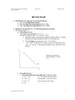
Figure 9.2 Block diagram of DME transponder.
Open in new tab (/mhe-lookup/tab-link/ch09fig02/6076385)
Share (/#copy_link)
The airborne unit actually measures the elapsed time between the transmis-
sion of the interrogation pulse-pair and the receipt of the reply pulse-pair and
converts this time by electrical means into distance indication. In other word,
the distance indication is a measurement of the range time of the pulse pairs.
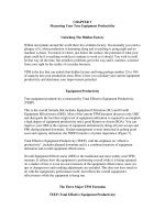
This timing sequence is easily seen by means of the system timing diagram of
Fig. 9.3. Timing starts in the range circuits of the airborne unit with the first
pulse of the interrogation pulse-pair. After a time delay, depending upon the
distance between the aircraft and the ground station, the interrogation pulses
are received at the antenna of the ground transponder beacon. The interroga-
tion pulses are decoded and the reply is encoded and transmitted after a pre-
set time delay (the reply delay of the ground station). This reply delay has dura-
tion of 50 microseconds which the airborne range circuits automatically ac-
7/51
1/9/2021 DISTANCE MEASURING EQUIPMENT | McGraw-Hill Education - Access Engineering
count for. Thus, the total time elapsed for any interrogation response cycle is
the sum of reply pulse spacing, the two way transit time (range time), and the
reply delay as shown in Fig. 9.3.
Figure 9.3 System timing diagram.
Open in new tab (/mhe-lookup/tab-link/ch09fig03/6076385)
Share (/#copy_link)
EXAMPLE 1
The total time elapsed between an aircraft interrogation and receipt of a
reply to that interrogation is 185.6 μs. What is the distance between the air-
craft and ground transponder in NM?
The reply delay is adjustable and must be maintained 50 μs for an error in
distance measurement results. An error adjustment is 12.36 μs, which is an
extra ordinary error and would results in an inherent system error of one
NM. The accuracy of the system distance readings depends upon the ac-
curacy of the reply delay, the airborne time measuring circuits, the airborne
indicators, and the rise time of the pulse used in the system. The transpon-
der beacon transmits at a rate of 1350 pairs per second, which are distance
replies and squitter, with the total distance replies limited to 5400 pulse
pairs per seconds. It should now be clear about DME function of both air-
borne and ground equipment. Each has a specific function in the process
of distance determination.
9.3.2. Basic System Function of DME
a. Airborne Unit
Producing and transmitting a properly coded interrogation signal on
any of the 126 channels assigned to the interrogation function.
Receiving and processing replies transmitted by a transponder
beacon assigned to any one of the 126 channels designated for reply
purposes.
Examining the reply coding and rejection of those signals which do
not possess the proper pulse spacing.
Recognizing the correct replies by a sorting process
8/51
1/9/2021 DISTANCE MEASURING EQUIPMENT | McGraw-Hill Education - Access Engineering
Measuring the elapsed time between an interrogation and its reply
and converting this time measurement to a distance indication.
Recognizing and reproducing, as an audible indicator to the pilot, the
identification signal transmitted by the transponder beacons.
b. Transponder Beacons
Receiving interrogations on one assigned frequency of the 126 fre-
quencies available.
Examining the coding of the interrogation pulses and initiating replies
only to those which possess the proper spacing
Generating coded reply pulse-pairs at appropriate power level on the
assigned reply frequency
Maintaining a 50 μs reply delay for system accuracy
Arranging a signal priority system.
9.4. CHOICE OF OPERATING
FREQUENCY
There are three major considerations that determine which band of frequen-
cies is optimum for use by pulse type DME.
The band chosen must have sufficient bandwidth to permit the efficient
transmission of pulses on the number of channel dedicated by the require-
ments of the aviation application.
The propagation conditions attending the frequencies in the chosen band
must be such that they will permit reliable transmission of information
with use of minimum power.
The band chosen must be such that the available techniques will permit
design of equipment with minimum weight.
In free space the power input to a radio receiver will be
(9.1)
where,
Pt is the transmitted power,
Gt is the gain of the transmitting antenna,
Gr is the gain of the receiving antenna and;
r is the distance between receiver and transmitter
λ is the transmitting wavelength.
There is a minimum power at a radio receiver is able to respond, and to furnish
this power to the receiver, the minimum required transmitter power will be
(9.2)
The DME antennas employed on the ground have an omni-directional pattern in
the horizontal plane and a directive pattern in the vertical plane. For such an ar-
ray having a length L and employing elements spaced less than one
9/51
1/9/2021 DISTANCE MEASURING EQUIPMENT | McGraw-Hill Education - Access Engineering
wavelength apart, the gain, to a first approximation, will be
(9.3)
Substituting Equation (9.3) in Equation (9.2), the minimum power required will
be
(9.4)
From Equation (9.4), it appears that it is possible to maintain the minimum
power required at all frequencies at exactly the same value merely by changing
the length of the receiving array. The beam width becomes narrow as the array
is lengthened. The angle in the vertical plane eventually reaches such a small
value that a large overhead cone of no signal is introduced, thereby no service
will be supplied to the aircraft other than those at long distances. A linear array
of about 7 feet has been found to be the most practical length for any fre-
quency that would be suitable for distance measurement use.
The aircraft antenna will always be limited by aerodynamic considerations,
which are determined by physical size. Therefore, it is not unreasonable to as-
sume that Gt at all frequencies will be approximately same. The simplified form
is
(9.5)
f is transmitting frequency in MHz. K is constant derived from Equation (9.4).
Considering the frequencies suitable for DME and setting the minimum power
at 10,000 MHz at zero dB, the Table 9.1 shows the power required at various
frequencies.
Table 9.1 Minimum required power versus frequency
Frequency in MHz 10,000 5,000 3,000 1000 500 200
Pt (min) in dB 0 –3 –5.2 –10 –13 –17
Open in new tab (/mhe-lookup/tab-link/ch09table01/6076385)
Download data (/mhe-lookup/download-link/ch09table01/6076385)
Share (/#copy_link)
It indicates that equipment operating at a 200 MHz would require 17-dB of 10/51
power less than that operating at 10,000 MHz. This power difference is very
significant, particularly since the power available from airborne equipment is
limited. In Equation (9.5) the calculations are based on free space conditions,
but this condition does not prevail in actual operating conditions. For long dis-
tance, quasi-optical path, however the attenuation will increase with frequency.
Therefore, the most advantageous frequency for DME operation would be be-
low about 1500 MHz.
In consideration of equipment design, it is possible to produce equipment
within the range of about 200 to 1500 MHz with approximately the same tech-
nique. Connection to the antenna may be made through solid dielectric lines.
At frequencies above 1500 MHz it becomes necessary to use magnetrons as
frequency generators, and connection to the antenna is made through wave-
/>
1/9/2021 DISTANCE MEASURING EQUIPMENT | McGraw-Hill Education - Access Engineering
guides. Because of the differing techniques above and below 1500 MHz, equip-
ment designed for higher frequency band has approximately twice the weight
that of in the lower band. Therefore, the equipment factor favors frequencies
lower than 1500 MHz for DME use.
It is now necessary to contrast frequencies at 200 MHz with those at 1000
MHz. Accuracy of DME demands short pulses. It has been shown that the half-
power bandwidth for the square pulse of 't' microseconds (μs) is
(9.6) 11/51
Δf will be in MHz if 't' is expressed in μs. Pulse lengths of the order of 2 μs will
require a channel width of 1 MHz together with some guard space. Operating
conditions demand at least 20 radio frequency channels; therefore, a minimum
spacing of about 25 MHz is required. There may have been some advantages
in the use of frequencies in band midway between 500 to 1000 MHz. However,
these advantages are minor and allocation prior to consideration of DME ser-
vice did not permit the later section of such a band. The band selected for in-
ternational standardization was 960 to 1215 MHz. This band is probably some-
what higher in frequency than the optimum, but considering the many ramifica-
tions involved in international agreements on matters of frequency, this choice
represents a fair approximation to the optimum.
9.4.1. Number of Channels
Modern aircrafts fly at altitudes as high as 45,000 feet and at this height the ra-
dio of horizon is 310 NM. An aircraft flying at this altitude, can receive radio
signals from UHF station located in an area of 250,000 squares NM centered
about the projection on the ground of the position of the aircraft. It is imprac-
tical, however to space facilities at a distance of 560 NM because coverage
must also be provided when aircrafts are at low altitudes. To provide coverage
to a distance of 50 NM to aircraft at altitudes as low as 1300 feet, it is pro-
posed to locate facilities with average spacing between them of 100 NM. A
spacing of 100 NM between stations means that in general, there will be one
station for each 10,000 square miles of area. To provide satisfactory service,
therefore a minimum of 25 non-interfering DME operating channels must be
provided.
Service is often dictated by the requirements of approach and landing zones,
which are considered to have a diameter of 30 NM or an area of approximately
700 square miles. The number of such areas, within a circle of 310 NM radius,
is a function of the density of air operation. If the entire area of 25,000 square
miles were filled with approach areas as many as 360 stations operating on as
many non-interfering channels would be required for DME service. These chan-
nels may be provided by either two methods or their combination or combina-
tion of them. One method for providing operating channels is to use clear radio
frequency channel. Since there are 255 MHz available in the distance-measur-
ing band, 200 clear channels could be provided with spacing of approximately
1.25 MHz per channel. Such spacing was proposed at one of the meetings of
the RTCA held in 1948 and time-to-time ICAO has reviewed the DME specifica-
tions with consent of contracting states.
The other method of providing operating channels is by use of a technique
known as pulse-multiplex. With this method double pulses are employed. Each
channel (both interrogation and replies) employs a different length of time
between the pulses of the pair. A demodulator is used to separate the interrog-
ation intended for one beacon from those intended for another beacon operat-
ing on the same radio frequency. A similar device is used to separate the
replies coming from a desired beacon from those transmitted by an unwanted
/>
1/9/2021 DISTANCE MEASURING EQUIPMENT | McGraw-Hill Education - Access Engineering
beacon operating on the same radio channel. In the system suggested by ICAO
for development only 20 radio frequency channels were employed to produce
100 operating channels. The pulse multiplex system however is not recom-
mended due to complicated design of equipment.
9.4.2. Types of DME 12/51
It can be classified based on RF power deliver to antenna and facility
performance.
9.4.2.1. Based on RF Power
(a) Low Power DME (LPDME)
LPDME is a component of ILS capability for precision and non-precision ap-
proaches that measure the distance from the aircraft to the runway. It generally
has a range of 40 NM from the airport. It aids not only in the approach but also
in allowing pilots to remain position oriented around the airport. This orienta-
tion is especially valuable in high terrain locations, and helps airplanes to avoid
obstacles or restricted areas. LPDME equipment in aircraft sends a pulse sig-
nal to the ground based LPDME, which responds with an answer pulse signal.
The ground based LPDME is a transponder; it answers a querying pulse. The
receiver in the aircraft measures the time delay between the sent and received
pulses and calculates the slant range distance. There is no azimuth informa-
tion, only distance. LPDME and DME (high power) differ only in the amplifica-
tion of the signal from the ground based unit. The LPDME is primarily used for
ILS in-lieu of marker beacons. Besides the advantage of helping pilots remain
position oriented during the entire approach. LPDME is often cheaper than us-
ing 'Marker Beacons' because of the real estate requirements. Marker Beacons
must be at a set distance and be located along the line of ILS approach.
(b) High Power DME (HPDME)
Aircrafts use DME to determine their distance from a land based transponder
by sending and receiving pulse pairs, i.e., two pulses of fixed duration and sep-
aration. The ground stations are typically collocated with VORs/DVOR. A typ-
ical DME ground transponder system for enroute navigation will have a 1 KW
peak pulse output on the assigned UHF channel. It has generally a range of 200
NM from the facility site or airports.
9.4.2.2. Facility Performance
(a) DME/W
This system is serving operational needs of en-route/terminal approach
(TMA)/navigation, where W stands for wide spectrum characteristics. This
DME is first generation equipment and have higher range of error as compare
to current IACO SARPs.
(b) DME/N
This system is serving operational needs of en-route/terminal approach
(TMA)/navigation, where N stands for narrow spectrum characteristics. This
DME is second generation equipment and have less range of error compared
to DME/W.
(c) DME/P
This system is the basic element of MLS, where P stands for precise distance
measurement. The spectrum characteristics are those of DME/N. This DME is
third generation equipment and less range error than DME/N. At present this
equipment will be used for the Performance Based Navigation (PBN) as well in
addition to MLS or ILS.
/>
1/9/2021 DISTANCE MEASURING EQUIPMENT | McGraw-Hill Education - Access Engineering
9.5. EFFECT OF BUNCHING ON DIS-
TANCE MEASUREMENT
When a large number of aircrafts are interrogating a transponder on the same
frequency, it is inevitable that some pulses will be emitted so that in combina-
tion of a number of false signals are formed. There is no way, a demoder can
determine that the first pulse, it is receiving, is from one aircraft and the second
from another. When the spacing between these is equivalent to and for which
the delay line has been adjusted, a reply will be generated. These replies are of
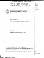
no use to either of the interrogating aircraft. This phenomenon is shown in Fig.
9.4 to how a spurious response may be generated by the presence of a pair of
pulses B with a spacing of 21 μs. Pulse pairs B start 14 μs after second pulse A
to produce a spurious pair.
Figure 9.4 Shows of bunching effect on DME.
Open in new tab (/mhe-lookup/tab-link/ch09fig04/6076385) 13/51
Share (/#copy_link)
The ratio of the number of total interrogations to true interrogations is given by
(9.7)
In Equation (9.7), ns is the total number of interrogations, n is the number of
true interrogation pairs and is equal to the average interrogation rate times, the
total number of aircraft interrogating the beacon, W is the width of the pulses
in seconds, and M is the number of modes per interrogation in radio frequency.
From the specification of the International Civil Aviation Organization (ICAO), M
= 10.
For the ratio (ns/n) for varying numbers of aircrafts that are interrogating a
transponder designed to the specification. It is assumed that the rate of inter-
rogation during searching period is 150 double pulses, and that the rate of in-
terrogation during the time that the airborne equipment is locked to the reply is
30 double pulses per second. It is further assumed that 90% of the aircrafts
have their equipment locked to the replies and only 10% are searching. The
width of the pulses is 2.5 μs. Under the foregoing assumption, what is the aver-
age rate of the double pulses per second per aircraft?
Therefore
Hence, the average rate 42 double pulses per second per aircraft are con-
sidered for further assumptions. Since each radio frequency interrogation
channel is employed with 10 pulse modes, the total number of aircraft that are
demanding service within range of a transponder is 10 times the ratio of total
authentic interrogation. It is observed that for 25 aircraft the number of total
/>
1/9/2021 DISTANCE MEASURING EQUIPMENT | McGraw-Hill Education - Access Engineering
challenges received is 2.13 times the number of bonafide interrogations, it
means that there is a total of 250 aircraft within the range of the transponder in
question but only 25 are expecting service from it. The remaining 225 aircraft
are demanding service from other transponders but are using operating chan-
nel based on identical radio frequency channels for interrogating.
If the spurious pulses increase as a function of the number of aircraft bonafide
interrogation to the transponder, the ratio of the number of false interrogations
would increase. For example, for 50 aircraft, the number of bonafide interroga-
tions will be 50 × 42, but the transponder will be called on to produce 3.26
times this number of replies. The number of interrogations for 100 aircraft will
be 100 × 42 pulse pairs but the number of total interrogations will be 5.52
times this product. The data brings out the fact that the additional operating
channels secured through pulse multiplex operation are not obtained without
sacrifice.
The data were computed on the assumption that in all cases the desired peak
power is 2.5 kilowatts. It can be seen that in clear channel operation, an in-
crease of approximately 26 Watts is required if it is decided to provide service
to 100 rather than to 50 aircraft, but with pulse multiplex operation, an increase
of about 320 Watts is required for similar increase in service. The transponder
reply efficiency is defined as the ratio of the number of true replies to true inter-
rogations; but it is also approximately equal to the total number of replies to
the total number of interrogations and is given by
(9.8) 14/51
where, td is the transponder dead time. The reply efficiency also represents the
probability of any interrogation affecting a reply.
It can be seen that with 50 aircraft, the efficiency is about 52%, i.e., there is ap-
proximately an equal chance that a reply will or will not be made. For 100 air-
craft interrogating the beacon, the efficiency drops to about 24%. The replies
received from a single ground transponder will consist of a number are in re-
sponse to the desired interrogation, a number in response to the interrogations
by other aircraft, and a number generated by bunching. All of these replies are
received in the airborne receiver and passed to the demoder, which in turn gen-
erates false pulses by bunching. There is a gate that accepts pulses for only a
given period of time. The total number of replies per second at the output of
the receiver demoder times the length of the gate gives the number of un-
desired replies that will adversely affect the operation of the equipment.
It will be seen that with 25 aircraft interrogating each of 10 beacons (total of
250 aircraft) and with all 10 beacons within radio line-of-sight and on the same
radio frequency channel, there will be 0.175 false replies per interrogation. With
120 aircraft interrogating each beacon, there will be two false replies per each
interrogation. To explain further, if an aircraft operates an interrogator with this
pulse multiplex system in a high density ground transponder area where there
are 25 aircrafts each interrogating one of 10 transponders, then for each 100
double pulse signal sent out, there will be on the average 78 desired replies, 17
undesired replies and 5 blanks.
The above discussion has clearly indicated the limitations of pulse multiplex
operation with high-density traffic. Economy of radio-frequency channels is
achieved by limiting the amount of service that can be provided.
9.5.1. Moding and Demoding
/>
1/9/2021 DISTANCE MEASURING EQUIPMENT | McGraw-Hill Education - Access Engineering
In DME, 20 radio frequency channels are used to provide 100 operating chan-
nels by employing cross-band operation i.e., the same radio frequency is used
to interrogate 10 different transponders, each of aircraft replies on a different
radio frequency. It might appear that this system would be sufficient to provide
satisfactory service and indeed this would be true if the number of aircraft in-
terrogating the transponder were small. However each time DME interrogation
is transmitted, all 10 transponders would reply, although only one useful reply
would be received back in the aircraft. It is thus seen that if 50 aircrafts were
interested in information from each of the 10 transponders, and each transpon-
der would have to make 500 replies. It would be necessary for each transpon-
der to have transmitters with large capacities to transmit power that would be
unused by the aircraft. Further, it would be necessary for responder to discard
the unwanted replies from 500 replies. It is clear, therefore, there must be
means further employed for segregating the desired interrogations and replies
from those that serve no useful purpose.
The method employed to segregate the useful replies from the undesired inter-
rogations and replies is the pulse mode. Pulse moding not only keeps the un-
wanted interrogation from reaching the transmitter in the ground transponder
and the unwanted replies from reaching DME, but serves to give an improve-
ment in S/N ratio in the video stages of both airborne and ground equipment.
9.5.2. Type of Moding
There are a variety of pulse moding methods which may be used for this type
of application. However, pulse-space moding is given by the specification of
ICAO. In this system, all interrogations and replies take the form of double
pulses. The space between the pulses of a pair is varied to provide the desired
mode. The interrogation modes of the specification are 14, 21, 28, 35, 42, 49,
56, 63, 70 and 77 μs. For example, the 10 interrogation and 10 replies times
between the leading edges of the pulse forming an interrogation or reply pair. It
is seen that the timings are identical for interrogation and reply, except that the
second set of number is listed in order of diminishing magnitudes, whereas the
first set is listed in order of increasing magnitudes. The method of employing
the modes is such that a widely spaced interrogation mode is employed with a
narrowly spaced reply mode and vice-versa.
9.6. DME EQUIPMENT DESCRIPTION 15/51
The DME system is comprised of a DME ground station and on-board equip-
ment in the aircraft. An interrogator in the aircraft transmits signals to the
ground station. The DME evaluates the interrogation pulses, and if they are
valid, transmits a reply on a different frequency. The interrogator measures the
elapsed time for the round-trip and converts this time to a distance indication
(in NM). An identification signal is transmitted by the DME approximately every
30 seconds; therefore, the pilot can positively identify the selected station.
Each interrogator transmits interrogation pulse pairs at a constant rate and
listens for replies from the ground station. Interrogations and replies have a
time-distance relationship. For the airborne DME to display a distance, several
successive time-distance interrogation replies must be received by the inter-
rogator. When distance is displayed, the system condition is known as 'lock-on'.
Other interrogations will not affect the system, because the time-distance rela-
tionship is not correct. A typical DME can be interrogated simultaneously by a
maximum of 100 aircraft interrogators (within range and tuned to its channel).
9.6.1. DME Operating Principles
/>
1/9/2021 DISTANCE MEASURING EQUIPMENT | McGraw-Hill Education - Access Engineering
The DME system requires a single channel receiver-transmitter combination
(transponder beacon) in conjunction with a special omni-directional antenna as
the ground station, and a multi channel receiver-transmitter combination (inter-
rogator) on board the aircraft. One multi channel airborne receiver-transmitter
(transmitting and receiving coded, pulsed information) provides both the dis-
tance and identification functions. The DME system has 252 operating chan-
nels, with the adjacent channels spaced 1MHz apart. For air-to-ground trans-
mission i.e., interrogation, there are 126 channels within the frequency band of
1025 MHz to 1150 MHz. For ground-to-air transmission i.e., reply, there are 63
channels in the frequency of 962 MHz to 1024 MHz, additional 63 channels in
the frequency band of 1151 MHz to 1213 MHz. The DME system utilizes pulse-
coding techniques in the transmission of its intelligence. The transmissions
are composed of pulse groups with a prearranged spacing between the pulses
of the group. For X-Channels, the interrogation pulses and the transponder
reply pulses are both spaced 12 μs apart. For Y-Channels, the interrogation
pulses are spaced at 36 μs, and the transponder reply pulses are spaced at 30
μs. Both the interrogator and transponder receivers employ pulse decoders,
which are set to pass only pulse pairs of the pre-defined spacing. The purpose
of the two pulse technique is to increase the S/N ratio and to discriminate
against pulse interference, such as might be produced by radar transmission
and other extraneous sources of RF energy on the frequency. The intelligence
supplied to the aircraft by the DME transponder is both identity and distance
information. The identity information is necessary for the pilot to positively
identify the station that has been selected. Identity information is provided to
the aircraft approximately every 30 seconds. The distance information, how-
ever, is provided to the aircraft only upon demand. Each aircraft must interrog-
ate the ground facility by means of the coded interrogation pulse-pairs, before
the transponder beacon can generate and transmit distance information.
The transponder beacon must be interrogated by the aircraft before the ground
facility can transmit usable distance information. Assuming an aircraft has in-
terrogated the ground facility, the interrogation signal is received at the beacon
antenna, and then routed to the receiver through the circulator and preselect-
ors. The signal is amplified, detected, and fed to the decoder for verification of
proper pulse spacing. The signal decoded from the decoder in turn triggers the
encoder and priority logic circuits, which encode a reply with the proper pulse
spacing and delay. The output from this unit is routed to the pulse shaper,
where the encoded replies are shaped into 3.5 μs pulses and amplified. The
shaped pulses modulate the gated RF from the exciter in the transmitter to pro-
duce the RF output pulses. The output pulses are then sent to the antenna and
radiated to the aircraft as reply pulse pairs.
Figure 9.5 Basic block diagram of DME operation.
Open in new tab (/mhe-lookup/tab-link/ch09fig05/6076385)
16/51
1/9/2021 DISTANCE MEASURING EQUIPMENT | McGraw-Hill Education - Access Engineering
Share (/#copy_link)
Three separate signals are transmitted by the beacon as a train of pulse-pairs. 17/51
These signals, in order of priority, are identification, replies to interrogations,
and squitter pulse-pairs (used as fill-in pulses). This priority system prevents
any interference between the three signals in the overall pulse train. The identi-
fication of the ground facility is important to the using aircraft; therefore, it has
been assigned first priority in the priority system. The generation of identifica-
tion intelligence is a function of the encoder. Identification is transmitted peri-
odically in International Morse code with the characters of the code consisting
of a periodic train of pulse pairs. Identification keying occurs approximately
every 30 seconds. When keyed, the priority logic circuit input is disabled; and
the circuits will not accept any decodes from the receiver. The replies to an in-
terrogation signal are second in the order of priority. Their induction into the
pulse train must be controlled (to prevent interference with the identity cycle
and to establish priority over the squitter pulses). This is accomplished by al-
lowing them to enter the pulse train only during a time interval not occupied by
the identity cycle. This is a major portion of the time, since the identity cycle
only occurs approximately every 30 seconds. Once the receiver accepts an in-
terrogation and decodes it, a blanking gate is generated (the so-called dead-
time gate). The dead-time gate is used to inhibit the transponder decoder for
approximately 60 μs. During this period, the decoded interrogation is delayed a
predetermined amount of time and transmitted back as a reply. The total delay
from the time of a received interrogation to transmission of a reply is typically
set for 50 μs. The squitter pulses are third in the order of priority. In the ab-
sence of interrogations or identity information, random squitter pulses are gen-
erated to maintain an average output pulse train of 1000 pulses-pairs per
second (PPS). The purpose of transmitting squitter pulses is to stabilize the
AGC circuits in the aircraft interrogator.
The process of distance measuring originates in the airborne unit with the gen-
eration and transmission of pulse signals called interrogations. The airborne
transmitter repeatedly initiates and transmits pulse signals consisting of pulse-
pairs having 12 μs spacing, a pulse-width of 3.5 μs, and a Gaussian or Sine
squared shape. These pulse-pairs are recovered by the transponder beacon re-
ceiver, whose output triggers the associated transmitter into transmitting reply
pulse-pairs. The reply pulse-pairs are received by the airborne receiver and tim-
ing circuits, which automatically measure round-trip travel time i.e., the time in-
terval between interrogation and reply pulses and convert this time into the
electrical signals that operate the distance meter.
Using the block diagram of the system as in Fig. 9.6, the distance measure-
ment function of the system can be examined. The range circuits of the air-
borne interrogator initiate the distance measuring process which formulates
pulse-pairs and transmits as an interrogation pulse-pair. This interrogation
pulse-pairs is received at a ground station antenna and sent to the receiver
where pulse pairs are amplified and detected as video pulse-pairs. They are
then fed to the decoder, where the pulses are examined for proper coding (spa-
cing and width) and decoded, if such proper coding exists. The output of the
decoder then triggers the encoder, which encodes a reply signal with the
proper pulse spacing. The output of this unit (pulse-pairs) is routed to the pulse
shaper, where the pulses are shaped, amplified, and routed to the transmitting
section for modulation of the gated RF. The output RF pulses are then radiated
into space (as replies) via the antenna. The reply pulses are received by the air-
craft, decoded by the airborne receiver, and examined by the range circuits for
synchronism with the airborne unit's own randomly generated interrogation
pulses.
Figure 9.6 Block diagram of ground DME transponder.
/>
1/9/2021 DISTANCE MEASURING EQUIPMENT | McGraw-Hill Education - Access Engineering
Open in new tab (/mhe-lookup/tab-link/ch09fig06/6076385) 18/51
Share (/#copy_link)
The airborne unit measures the elapsed time between the transmission of the
interrogation pulse- pair and the receipt of the reply pulse-pair. It then, converts
this time into a distance indication. In other words, the distance indication is a
measurement of the range time of the pulse-pairs. This timing sequence is
easily seen by means of the system timing diagram discussed in the previous
section. Timing starts with the first pulse of the interrogation pulse-pair. After a
time delay, depending upon the distance between the aircraft and the ground
station, the interrogation pulses are received at the antenna of the ground
transponder beacon. The interrogation pulses are decoded, and the reply is en-
coded and transmitted after a preset time delay i.e., the reply delay of the
ground station. This reply delay has duration of 50 μs, for which the airborne
range circuits automatically account. Thus, the total time lapse for any inter-
rogation response cycle is the sum of reply pulse spacing, the two-way transit
time (range time), and the reply delay.
9.6.2. Theory of Operation
The simplified block diagram of the DME is presented in Fig. 9.7. The transpon-
der portion of the DME consists of the Directional Coupler (DC), Circulator, First
Mixer, IF Amplifier, Preselector, Power Amplifier, and RF Generator as well as
the Decoder, Keyer, and Transmitter Video. Aircraft interrogations are picked-up
by the antenna and routed through the DC to the Circulator. Additional interrog-
ations from the Diode Modulator are injected into the DC. The responses to
these interrogations are sampled at the monitor antenna and are used to mon-
itor the reply delay and reply efficiency. The DC provides a sample of the
transponder reply to the monitor detector. The monitor detector provides a
sample of the transmitted reply to the test unit for power output measurement.
The circulator provides isolation between the transmitted and received signals,
since a common antenna is used for both. Signals applied to any of the ports
will experience the least insertion loss or minimum resistance when travelling
to the adjacent port in a clockwise direction. Signals travelling in a counter-
clockwise direction will be attenuated by at least 20-dB. Interrogations arriving
from the DC are directed to the preselector.
Figure 9.7 (a) Block diagram of operational DME.
/>
1/9/2021 DISTANCE MEASURING EQUIPMENT | McGraw-Hill Education - Access Engineering
Open in new tab (/mhe-lookup/tab-link/ch09fig07a/6076385) 19/51
Share (/#copy_link)
The pre-selector is a narrow-band, three-pole, mechanically tuned filter that dis-
criminates against undesired frequencies and provides additional attenuation
of transmitter energy. From the pre-selector, the received interrogation is direc-
ted to the first mixer. The Local Oscillator (LO) injection supplied by the RF gen-
erator is sent to the first mixer. This signal is separated by 63 MHz from the re-
ceived interrogation signal. The two signals are mixed and the resultant 63
MHz Intermediate Frequency (IF) is sent to the IF Amplifier.
The IF Amplifier is a logarithmic amplifier that provides a simple means of
compressing the large dynamic range of the input signal into a linear, non-limit-
ing output. Its circuit also provide short and long distance echo suppression,
narrow-pulse rejection, and CW suppression. It provides video pulses to the de-
coder. The decoder is comprised of several shift registers and gates. The video
pulses from the IF amplifier are sent to two separate paths (delayed and un-
delayed) for a coincidence comparison. If the pulse-pairs are spaced correctly,
a decoded output pulse is produced. The decoder also produces a dead-time
gate which inhibits the decoder until decodes, which represent an aircraft inter-
rogation, have been delayed, encoded, and transmitted back as replies. The de-
coder includes a noise generator that produces squitter pulses. Squitter pulses
are generated to maintain an average output pulse train of 1000 PPS. The de-
code signals are sent to the transmitter video. By the time signals reach this
point, the transmission has been established to conform to the following order
of precedence:
Identity pulse groups;
Decoded replies; and
Squitter pulse pairs;
Figure 9.7 (b) Block diagram of operational DME.
/>
1/9/2021 DISTANCE MEASURING EQUIPMENT | McGraw-Hill Education - Access Engineering
Open in new tab (/mhe-lookup/tab-link/ch09fig07b/6076385) 20/51
Share (/#copy_link)
The transmitter video contains a microprocessor that performs a variety of
tasks. Its primary function is to continually adjust reply delay to its selected
value. Information required to measure the reply delay is obtained from the
Monitor A via the TX power detector. Under normal conditions, the DME will re-
ceive identity keying from a collocated VOR or ILS. If this keying signal is
present, it will be gated through the Keyer to the transmitter video. If there is no
external keying for forty seconds, or if the signal is continuous for more than
five seconds, the external keying signal will be blocked, and an internal keying
signal will be generated by the Keyer. The code group is selected by means of
rocker switches installed on the Keyer. The DME Power Amplifier (PA) delivers
125 W peak at its output. This translates to a minimum 100 W output at the an-
tenna of the station allowing for normal losses in the connecting cables, DC,
etc. The output power is attainable on any DME channel from 962 MHz to 1213
MHz is 100 W for collocated and 1 KW for enroute facilities.
The PA consists of the Modulator and the RF Amplifier. The input from the
transmitter video consists of two rectangular pulses. The modulator portion of
the PA controls the position, shape, and amplitude of these pulses used to
modulate the RF amplifier portion. Additional circuitry is included in the modu-
lator, which is controlled by the microprocessor during the process of adjusting
system delay (Search Mode). During the search mode, a control signal from the
Microprocessor Unit (MPU) is applied to gating circuits, which inhibit the power
amplifier and enable the video-shaped pulses for the monitor half-amplitude
finder (HAF) to be passed to the monitor. The MPU uses these HAF output
pulses to measure and set system delay. This insures that no replies to aircraft
interrogations will be transmitted until proper system delay control has been
established (Track Mode). The input to PA is a nominal 450 mW CW signal
from the RF generator. The PA utilizes at least four amplifier stages to produce
shaped RF pulses a 125 Watts peak level minimum.
The excitation for the PA is provided by the RF generator, which uses a phase-
locked loop to generate highly stable RF energy. The output frequency can be
set to any one of the 252 channels in the 962 MHz to 1213 MHz band by the
use of internal programming switches. The monitor portion of the DME con-
sists of two major sections: the signal generator i.e., for interrogating the
transponder and the monitor properly to evaluate the reply parameters. The
signal generator consists of the Video, Diode Modulator, RF generator, and Cal-
ibrated attenuator. In normal operation, the signal generator interrogates the
transponder 100 times per second at a fixed output level. This signal level sim-
ulates a close in aircraft and is used to monitor reply delay. When the test unit
is set to measure reply efficiency, the interrogation pulse repetition frequency
(PRF) is increased to 1000 PPS; and two different RF signal levels are altern-
ately generated. One level is dependent upon the setting of the calibrated at-
tenuator and is used to measure reply efficiency. The second level is main-
/>