THERE ONCE WAS A CLASSICAL THEORY: Introductory Classical Mechanics, with Problems and Solutions pdf
Bạn đang xem bản rút gọn của tài liệu. Xem và tải ngay bản đầy đủ của tài liệu tại đây (5.77 MB, 623 trang )
THERE ONCE WAS A
CLASSICAL THEORY…
Introductory Classical Mechanics,
with Problems and Solutions
David Morin
…Of which quantum disciples were leery.
They said, “Why spend so long
On a theory that’s wrong?”
Well, it works for your everyday query!
Copyright © 2004 by David Morin
All rights reserved
Contents
1 Statics I-1
1.1 Balancing forces . . . . . . . . . . . . . . . . . . . . . . . . . . . . . I-1
1.2 Balancing torques . . . . . . . . . . . . . . . . . . . . . . . . . . . . . I-5
1.3 Exercises . . . . . . . . . . . . . . . . . . . . . . . . . . . . . . . . . I-9
1.4 Problems . . . . . . . . . . . . . . . . . . . . . . . . . . . . . . . . . I-12
1.5 Solutions . . . . . . . . . . . . . . . . . . . . . . . . . . . . . . . . . I-17
2 Using F = ma II-1
2.1 Newton’s Laws . . . . . . . . . . . . . . . . . . . . . . . . . . . . . . II-1
2.2 Free-body diagrams . . . . . . . . . . . . . . . . . . . . . . . . . . . II-4
2.3 Solving differential equations . . . . . . . . . . . . . . . . . . . . . . I I-8
2.4 Projectile motion . . . . . . . . . . . . . . . . . . . . . . . . . . . . . II-12
2.5 Motion in a plane, polar coordinates . . . . . . . . . . . . . . . . . . II-15
2.6 Exercises . . . . . . . . . . . . . . . . . . . . . . . . . . . . . . . . . II-18
2.7 Problems . . . . . . . . . . . . . . . . . . . . . . . . . . . . . . . . . II-24
2.8 Solutions . . . . . . . . . . . . . . . . . . . . . . . . . . . . . . . . . II-28
3 Oscillations III-1
3.1 Linear differential equations . . . . . . . . . . . . . . . . . . . . . . . III-1
3.2 Simple harmonic motion . . . . . . . . . . . . . . . . . . . . . . . . . III-4
3.3 Damped harmonic motion . . . . . . . . . . . . . . . . . . . . . . . . III-6
3.4 Driven (and damped) harmonic motion . . . . . . . . . . . . . . . . III-8
3.5 Coupled oscillators . . . . . . . . . . . . . . . . . . . . . . . . . . . . III-13
3.6 Exercises . . . . . . . . . . . . . . . . . . . . . . . . . . . . . . . . . III-18
3.7 Problems . . . . . . . . . . . . . . . . . . . . . . . . . . . . . . . . . II I-22
3.8 Solutions . . . . . . . . . . . . . . . . . . . . . . . . . . . . . . . . . III-24
4 Conservation of Energy and Momentum IV-1
4.1 Conservation of energy in 1-D . . . . . . . . . . . . . . . . . . . . . . IV-1
4.2 Small Oscillations . . . . . . . . . . . . . . . . . . . . . . . . . . . . . IV-6
4.3 Conservation of energy in 3-D . . . . . . . . . . . . . . . . . . . . . . IV-8
4.3.1 Conservative forces in 3-D . . . . . . . . . . . . . . . . . . . . IV-9
4.4 Gravity . . . . . . . . . . . . . . . . . . . . . . . . . . . . . . . . . . IV-12
4.4.1 Gravity due to a sphere . . . . . . . . . . . . . . . . . . . . . IV-12
4.4.2 Tides . . . . . . . . . . . . . . . . . . . . . . . . . . . . . . . IV-14
1
2 CONTENTS
4.5 Momentum . . . . . . . . . . . . . . . . . . . . . . . . . . . . . . . . IV-17
4.5.1 Conservation of momentum . . . . . . . . . . . . . . . . . . . IV-17
4.5.2 Rocket motion . . . . . . . . . . . . . . . . . . . . . . . . . . IV-19
4.6 The CM frame . . . . . . . . . . . . . . . . . . . . . . . . . . . . . . IV-20
4.6.1 Definition . . . . . . . . . . . . . . . . . . . . . . . . . . . . . IV-20
4.6.2 Kinetic energy . . . . . . . . . . . . . . . . . . . . . . . . . . IV-22
4.7 Collisions . . . . . . . . . . . . . . . . . . . . . . . . . . . . . . . . . IV-23
4.7.1 1-D motion . . . . . . . . . . . . . . . . . . . . . . . . . . . . IV-23
4.7.2 2-D motion . . . . . . . . . . . . . . . . . . . . . . . . . . . . IV-25
4.8 Inherently inelastic processes . . . . . . . . . . . . . . . . . . . . . . IV-26
4.9 Exercises . . . . . . . . . . . . . . . . . . . . . . . . . . . . . . . . . IV-30
4.10 Problems . . . . . . . . . . . . . . . . . . . . . . . . . . . . . . . . . IV-41
4.11 Solutions . . . . . . . . . . . . . . . . . . . . . . . . . . . . . . . . . IV-47
5 The Lagrangian Method V-1
5.1 The Euler-Lagrange equations . . . . . . . . . . . . . . . . . . . . . . V-1
5.2 The principle of stationary action . . . . . . . . . . . . . . . . . . . . V-4
5.3 Forces of constraint . . . . . . . . . . . . . . . . . . . . . . . . . . . . V-10
5.4 Change of coordinates . . . . . . . . . . . . . . . . . . . . . . . . . . V-12
5.5 Conservation Laws . . . . . . . . . . . . . . . . . . . . . . . . . . . . V-15
5.5.1 Cyclic coordinates . . . . . . . . . . . . . . . . . . . . . . . . V-15
5.5.2 Energy conservation . . . . . . . . . . . . . . . . . . . . . . . V-16
5.6 Noether’s Theorem . . . . . . . . . . . . . . . . . . . . . . . . . . . . V-18
5.7 Small oscillations . . . . . . . . . . . . . . . . . . . . . . . . . . . . . V-21
5.8 Other applications . . . . . . . . . . . . . . . . . . . . . . . . . . . . V-24
5.9 Exercises . . . . . . . . . . . . . . . . . . . . . . . . . . . . . . . . . V-27
5.10 Problems . . . . . . . . . . . . . . . . . . . . . . . . . . . . . . . . . V-29
5.11 Solutions . . . . . . . . . . . . . . . . . . . . . . . . . . . . . . . . . V-34
6 Central Forces VI-1
6.1 Conservation of angular momentum . . . . . . . . . . . . . . . . . . VI-1
6.2 The effective potential . . . . . . . . . . . . . . . . . . . . . . . . . . VI-3
6.3 Solving the equations of motion . . . . . . . . . . . . . . . . . . . . . VI-5
6.3.1 Finding r(t) and θ(t) . . . . . . . . . . . . . . . . . . . . . . . VI-5
6.3.2 Finding r(θ) . . . . . . . . . . . . . . . . . . . . . . . . . . . VI-6
6.4 Gravity, Kepler’s Laws . . . . . . . . . . . . . . . . . . . . . . . . . . VI-6
6.4.1 Calculation of r(θ) . . . . . . . . . . . . . . . . . . . . . . . . VI-6
6.4.2 The orbits . . . . . . . . . . . . . . . . . . . . . . . . . . . . . VI-8
6.4.3 Proof of conic orbits . . . . . . . . . . . . . . . . . . . . . . . VI-10
6.4.4 Kepler’s Laws . . . . . . . . . . . . . . . . . . . . . . . . . . . VI-11
6.4.5 Reduced mass . . . . . . . . . . . . . . . . . . . . . . . . . . . VI-13
6.5 Exercises . . . . . . . . . . . . . . . . . . . . . . . . . . . . . . . . . VI-16
6.6 Problems . . . . . . . . . . . . . . . . . . . . . . . . . . . . . . . . . VI-18
6.7 Solutions . . . . . . . . . . . . . . . . . . . . . . . . . . . . . . . . . VI-20
CONTENTS 3
7 Angular Momentum, Part I (Constant
ˆ
L) VII-1
7.1 Pancake object in x-y plane . . . . . . . . . . . . . . . . . . . . . . . VII-2
7.1.1 Rotation about the z-axis . . . . . . . . . . . . . . . . . . . . VII-3
7.1.2 General motion in x-y plane . . . . . . . . . . . . . . . . . . . VII-4
7.1.3 The parallel-axis theorem . . . . . . . . . . . . . . . . . . . . VII-5
7.1.4 The perpendicular-axis theorem . . . . . . . . . . . . . . . . . VII-6
7.2 Non-planar objects . . . . . . . . . . . . . . . . . . . . . . . . . . . . VII-7
7.3 Calculating moments of inertia . . . . . . . . . . . . . . . . . . . . . VII-9
7.3.1 Lots of examples . . . . . . . . . . . . . . . . . . . . . . . . . VI I-9
7.3.2 A neat trick . . . . . . . . . . . . . . . . . . . . . . . . . . . . VII-11
7.4 Torque . . . . . . . . . . . . . . . . . . . . . . . . . . . . . . . . . . . VII-12
7.4.1 Point mass, fixed origin . . . . . . . . . . . . . . . . . . . . . VII-13
7.4.2 Extended mass, fixed origin . . . . . . . . . . . . . . . . . . . VII-13
7.4.3 Extended mass, non-fixed origin . . . . . . . . . . . . . . . . VII-14
7.5 Collisions . . . . . . . . . . . . . . . . . . . . . . . . . . . . . . . . . VII-17
7.6 Angular impulse . . . . . . . . . . . . . . . . . . . . . . . . . . . . . VII-19
7.7 Exercises . . . . . . . . . . . . . . . . . . . . . . . . . . . . . . . . . VII-21
7.8 Problems . . . . . . . . . . . . . . . . . . . . . . . . . . . . . . . . . VII-28
7.9 Solutions . . . . . . . . . . . . . . . . . . . . . . . . . . . . . . . . . VII-34
8 Angular Momentum, Part II (General
ˆ
L) VIII-1
8.1 Preliminaries concerning rotations . . . . . . . . . . . . . . . . . . . VIII-1
8.1.1 The form of general motion . . . . . . . . . . . . . . . . . . . VIII-1
8.1.2 The angular velocity vector . . . . . . . . . . . . . . . . . . . VIII-2
8.2 The inertia tensor . . . . . . . . . . . . . . . . . . . . . . . . . . . . VIII-5
8.2.1 Rotation about an axis through the origin . . . . . . . . . . . VIII-5
8.2.2 General motion . . . . . . . . . . . . . . . . . . . . . . . . . . VIII-9
8.2.3 The parallel-axis theorem . . . . . . . . . . . . . . . . . . . . VIII-10
8.3 Principal axes . . . . . . . . . . . . . . . . . . . . . . . . . . . . . . . VIII-11
8.4 Two basic types of problems . . . . . . . . . . . . . . . . . . . . . . . VIII-15
8.4.1 Motion after an impulsive blow . . . . . . . . . . . . . . . . . VIII-15
8.4.2 Frequency of motion due to a torque . . . . . . . . . . . . . . VIII-18
8.5 Euler’s equations . . . . . . . . . . . . . . . . . . . . . . . . . . . . . VIII-20
8.6 Free symmetric top . . . . . . . . . . . . . . . . . . . . . . . . . . . . VII I-22
8.6.1 View from body frame . . . . . . . . . . . . . . . . . . . . . . VIII-22
8.6.2 View from fixed frame . . . . . . . . . . . . . . . . . . . . . . VIII-24
8.7 Heavy symmetric top . . . . . . . . . . . . . . . . . . . . . . . . . . . VIII-25
8.7.1 Euler angles . . . . . . . . . . . . . . . . . . . . . . . . . . . . VIII-25
8.7.2 Digression on the components of ω . . . . . . . . . . . . . . . VIII-26
8.7.3 Torque method . . . . . . . . . . . . . . . . . . . . . . . . . . VIII-29
8.7.4 Lagrangian method . . . . . . . . . . . . . . . . . . . . . . . . VIII-30
8.7.5 Gyroscope with
˙
θ = 0 . . . . . . . . . . . . . . . . . . . . . . VIII-31
8.7.6 Nutation . . . . . . . . . . . . . . . . . . . . . . . . . . . . . VIII-33
8.8 Exercises . . . . . . . . . . . . . . . . . . . . . . . . . . . . . . . . . VIII-36
8.9 Problems . . . . . . . . . . . . . . . . . . . . . . . . . . . . . . . . . VII I-38
4 CONTENTS
8.10 Solutions . . . . . . . . . . . . . . . . . . . . . . . . . . . . . . . . . VIII-44
9 Accelerated Frames of Reference IX-1
9.1 Relating the coordinates . . . . . . . . . . . . . . . . . . . . . . . . . IX-2
9.2 The fictitious forces . . . . . . . . . . . . . . . . . . . . . . . . . . . IX-4
9.2.1 Translation force: −md
2
R/dt
2
. . . . . . . . . . . . . . . . . IX-5
9.2.2 Centrifugal force: −mω × (ω × r) . . . . . . . . . . . . . . . . IX-5
9.2.3 Coriolis force: −2mω × v . . . . . . . . . . . . . . . . . . . . IX-7
9.2.4 Azimuthal force: −m(dω/dt) × r . . . . . . . . . . . . . . . . IX-11
9.3 Exercises . . . . . . . . . . . . . . . . . . . . . . . . . . . . . . . . . IX-13
9.4 Problems . . . . . . . . . . . . . . . . . . . . . . . . . . . . . . . . . IX-15
9.5 Solutions . . . . . . . . . . . . . . . . . . . . . . . . . . . . . . . . . IX-17
10 Relativity (Kinematics) X-1
10.1 The postulates . . . . . . . . . . . . . . . . . . . . . . . . . . . . . . X-2
10.2 The fundamental effects . . . . . . . . . . . . . . . . . . . . . . . . . X-4
10.2.1 Loss of Simultaneity . . . . . . . . . . . . . . . . . . . . . . . X-4
10.2.2 Time dilation . . . . . . . . . . . . . . . . . . . . . . . . . . . X-7
10.2.3 Length contraction . . . . . . . . . . . . . . . . . . . . . . . . X-10
10.3 The Lorentz transformations . . . . . . . . . . . . . . . . . . . . . . X-14
10.3.1 The derivation . . . . . . . . . . . . . . . . . . . . . . . . . . X-14
10.3.2 The fundamental effects . . . . . . . . . . . . . . . . . . . . . X-18
10.3.3 Velocity addition . . . . . . . . . . . . . . . . . . . . . . . . . X-20
10.4 The invariant interval . . . . . . . . . . . . . . . . . . . . . . . . . . X-23
10.5 Minkowski diagrams . . . . . . . . . . . . . . . . . . . . . . . . . . . X-26
10.6 The Doppler effect . . . . . . . . . . . . . . . . . . . . . . . . . . . . X-29
10.6.1 Longitudinal Doppler effect . . . . . . . . . . . . . . . . . . . X-29
10.6.2 Transverse Doppler effect . . . . . . . . . . . . . . . . . . . . X-30
10.7 Rapidity . . . . . . . . . . . . . . . . . . . . . . . . . . . . . . . . . . X-32
10.8 Relativity without c . . . . . . . . . . . . . . . . . . . . . . . . . . . X-35
10.9 Exercises . . . . . . . . . . . . . . . . . . . . . . . . . . . . . . . . . X-39
10.10Problems . . . . . . . . . . . . . . . . . . . . . . . . . . . . . . . . . X-46
10.11Solutions . . . . . . . . . . . . . . . . . . . . . . . . . . . . . . . . . X-52
11 Relativity (Dynamics) XI-1
11.1 Energy and momentum . . . . . . . . . . . . . . . . . . . . . . . . . XI-1
11.1.1 Momentum . . . . . . . . . . . . . . . . . . . . . . . . . . . . XI-2
11.1.2 Energy . . . . . . . . . . . . . . . . . . . . . . . . . . . . . . . XI-3
11.2 Transformations of E and p . . . . . . . . . . . . . . . . . . . . . . . XI-7
11.3 Collisions and decays . . . . . . . . . . . . . . . . . . . . . . . . . . . XI-10
11.4 Particle-physics units . . . . . . . . . . . . . . . . . . . . . . . . . . . XI-13
11.5 Force . . . . . . . . . . . . . . . . . . . . . . . . . . . . . . . . . . . . XI-14
11.5.1 Force in one dimension . . . . . . . . . . . . . . . . . . . . . . XI-14
11.5.2 Force in two dimensions . . . . . . . . . . . . . . . . . . . . . XI-16
11.5.3 Transformation of forces . . . . . . . . . . . . . . . . . . . . . XI-17
CONTENTS 5
11.6 Rocket motion . . . . . . . . . . . . . . . . . . . . . . . . . . . . . . XI-19
11.7 Relativistic strings . . . . . . . . . . . . . . . . . . . . . . . . . . . . XI-22
11.8 Mass . . . . . . . . . . . . . . . . . . . . . . . . . . . . . . . . . . . . XI-24
11.9 Exercises . . . . . . . . . . . . . . . . . . . . . . . . . . . . . . . . . XI-26
11.10Problems . . . . . . . . . . . . . . . . . . . . . . . . . . . . . . . . . XI-30
11.11Solutions . . . . . . . . . . . . . . . . . . . . . . . . . . . . . . . . . XI-34
12 4-vectors XII-1
12.1 Definition of 4-vectors . . . . . . . . . . . . . . . . . . . . . . . . . . XII-1
12.2 Examples of 4-vectors . . . . . . . . . . . . . . . . . . . . . . . . . . XII-2
12.3 Properties of 4-vectors . . . . . . . . . . . . . . . . . . . . . . . . . . XII-4
12.4 Energy, momentum . . . . . . . . . . . . . . . . . . . . . . . . . . . . XI I-6
12.4.1 Norm . . . . . . . . . . . . . . . . . . . . . . . . . . . . . . . XII-6
12.4.2 Transformation of E,p . . . . . . . . . . . . . . . . . . . . . . XII-6
12.5 Force and acceleration . . . . . . . . . . . . . . . . . . . . . . . . . . XII-7
12.5.1 Transformation of forces . . . . . . . . . . . . . . . . . . . . . XII-7
12.5.2 Transformation of accelerations . . . . . . . . . . . . . . . . . XII-8
12.6 The form of physical laws . . . . . . . . . . . . . . . . . . . . . . . . XII-10
12.7 Exercises . . . . . . . . . . . . . . . . . . . . . . . . . . . . . . . . . XII-12
12.8 Problems . . . . . . . . . . . . . . . . . . . . . . . . . . . . . . . . . XII-13
12.9 Solutions . . . . . . . . . . . . . . . . . . . . . . . . . . . . . . . . . XII-14
13 General Relativity XIII-1
13.1 The Equivalence Principle . . . . . . . . . . . . . . . . . . . . . . . . XIII-1
13.2 Time dilation . . . . . . . . . . . . . . . . . . . . . . . . . . . . . . . XIII-2
13.3 Uniformly accelerated frame . . . . . . . . . . . . . . . . . . . . . . . XIII-4
13.3.1 Uniformly accelerated point particle . . . . . . . . . . . . . . XIII-5
13.3.2 Uniformly accelerated frame . . . . . . . . . . . . . . . . . . . XIII-6
13.4 Maximal-proper-time principle . . . . . . . . . . . . . . . . . . . . . XIII-8
13.5 Twin paradox revisited . . . . . . . . . . . . . . . . . . . . . . . . . . XIII-9
13.6 Exercises . . . . . . . . . . . . . . . . . . . . . . . . . . . . . . . . . XIII-12
13.7 Problems . . . . . . . . . . . . . . . . . . . . . . . . . . . . . . . . . XIII-15
13.8 Solutions . . . . . . . . . . . . . . . . . . . . . . . . . . . . . . . . . XIII-18
14 Appendices XIV-1
14.1 Appendix A: Useful formulas . . . . . . . . . . . . . . . . . . . . . . XIV-1
14.1.1 Taylor series . . . . . . . . . . . . . . . . . . . . . . . . . . . XIV-1
14.1.2 Nice formulas . . . . . . . . . . . . . . . . . . . . . . . . . . . XIV-2
14.1.3 Integrals . . . . . . . . . . . . . . . . . . . . . . . . . . . . . . XIV-2
14.2 Appendix B: Units, dimensional analysis . . . . . . . . . . . . . . . . XIV-4
14.2.1 Exercises . . . . . . . . . . . . . . . . . . . . . . . . . . . . . XIV-6
14.2.2 Problems . . . . . . . . . . . . . . . . . . . . . . . . . . . . . XIV-7
14.2.3 Solutions . . . . . . . . . . . . . . . . . . . . . . . . . . . . . XIV-8
14.3 Appendix C: Approximations, limiting cases . . . . . . . . . . . . . . XIV-11
14.3.1 Exercise . . . . . . . . . . . . . . . . . . . . . . . . . . . . . . XIV-13
6 CONTENTS
14.4 Appendix D: Solving differential equations numerically . . . . . . . . XIV-15
14.5 Appendix E: F = ma vs. F = dp/dt . . . . . . . . . . . . . . . . . . XIV-17
14.6 Appendix F: Existence of principal axes . . . . . . . . . . . . . . . . XIV-19
14.7 Appendix G: Diagonalizing matrices . . . . . . . . . . . . . . . . . . XIV-22
14.8 Appendix H: Qualitative relativity questions . . . . . . . . . . . . . . XIV-24
14.9 Appendix I: Lorentz transformations . . . . . . . . . . . . . . . . . . XIV-29
14.10Appendix J: Resolutions to the twin paradox . . . . . . . . . . . . . XIV-32
14.11Appendix K: Physical constants and data . . . . . . . . . . . . . . . XIV-34
Preface
This textbo ok has grown out of the first-semester honors freshman physics course
that has been taught at Harvard University during recent years. The book is essen-
tially two books in one. Roughly half of it follows the form of a normal textbook,
consisting of text, along with exercises suitable for homework assignments. The
other half takes the form of a problem book, with all sorts of problems (with so-
lutions) of varying degrees of difficulty. If you’ve been searching for a supply of
practice problems to work on, this should keep you busy for a while.
A brief outline of the book is as follows. Chapter 1 covers statics. Most of this
will probably look familiar, but you’ll find some fun problems. In Chapter 2, we
learn about forces and how to apply F = ma. There’s a bit of math here needed
for solving some simple differential equations. Chapter 3 deals with oscillations
and coupled oscillators. Again, there’s a fair amount of math needed for solving
linear differential equations, but there’s no way to avoid it. Chapter 4 deals with
conservation of energy and momentum. You’ve probably seen much of this before,
but again, it has lots of neat problems.
In Chapter 5, we introduce the Lagrangian method, which will undoubtedly be
new to you. It looks rather formidable at first, but it’s really not all that rough.
There are difficult concepts at the heart of the subject, but the nice thing is that
the technique is easy to apply. The situation here analogous to taking a derivative
in calculus; there are substantive concepts on which the theory rests, but the act of
taking a derivative is fairly straightforward.
Chapter 6 deals with central forces, Kepler’s Laws, and such things. Chapter 7
covers the easier type of angular momentum situations, ones where the direction of
the angular momentum is fixed. Chapter 8 covers the more difficult type, ones where
the direction changes. Gyroscopes, spinning tops, and other fun and perplexing
objects fall into this category. Chapter 9 deals with accelerated frames of reference
and fictitious forces.
Chapters 10 through 13 cover relativity. Chapter 10 deals with relativistic kine-
matics – abstract particles flying through space and time. Chapter 11 covers rel-
ativistic dynamics – energy, momentum, force, etc. Chapter 12 intro duces the im-
portant concept of “4-vectors.” The material in this chapter could alternatively
be put in the previous two, but for various reasons I thought it best to create a
separate chapter for it. Chapter 13 covers a few topics from general relativity. It’s
not possible for one chapter to do this subject justice, of course, so we’ll just look
at some basic (but still very interesting) examples.
1
2 CONTENTS
The appendices contain various useful things. Indeed, Appendices B and C,
which cover dimensional analysis and limiting cases, are the first parts of this book
you should read.
Throughout the book, I have included many “remarks.” These are written in
a slightly smaller font than the surrounding text. They begin with a small-capital
“Remark” and end with a shamrock (♣). The purpose of these remarks is to say
something that needs to be said, without disrupting the overall flow of the argument.
In some sense these are “extra” thoughts, although they are invariably useful in
understanding what is going on. They are usually more informal than the rest of
the text, and I reserve the right to occasionally use them to babble about things
I find interesting, but which you may find a bit tangential. For the most part,
however, the remarks address issues and questions that arise naturally in the course
of the discussion.
At the end of the solutions to many problems, the obvious thing to do is to
check limiting cases.
1
I have written these in a smaller font, but I have not always
bothered to start them with a “Remark” and end them with a “♣”, because they
are not “extra” thoughts. Checking limiting cases of your answer is something you
should always do.
For your reading pleasure (I hope), I have included many limericks scattered
throughout the text. I suppose that they might be viewed as educational, but they
certainly don’t represent any deep insight I have on the teaching of physics. I have
written them solely for the purpose of lightening things up. Some are funny. Some
are stupid. But at least they’re all physically accurate (give or take).
A word on the problems. Some are easy, but many are very difficult. I think
you’ll find them quite interesting, but don’t get discouraged if you have trouble
solving them. Some are designed to be brooded over for hours. Or days, or weeks,
or months (as I can attest to). I have chosen to write them up for two reasons: (1)
Students invariably want extra practice problems, with solutions, to work on, and
(2) I find them rather fun.
The problems are marked with a number of asterisks. Harder problems earn
more asterisks, on a scale from zero to four. You may, of course, disagree with
my judgment of difficulty, but I think that an arbitrary weighting scheme is better
than none at all. As a rough idea of what I mean by the number of stars: one-star
problems are solid problems that require some thought, and four-star problems are
really really really difficult. Try a few and you’ll see what I mean.
Just to warn you, even if you understand the material in the text backwards and
forwards, the four-star (and many of the three-star) problems will still be extremely
challenging. But that’s how it should be. My goal was to create an unreachable
upper bound on the number (and difficulty) of problems, because it would be an
unfortunate circumstance, indeed, if you were left twiddling your thumbs, having
run out of problems to solve. I hope I have succeeded.
For the problems you choose to work on, be careful not to look at the solution
too soon. There is nothing wrong with putting a problem aside for a while and
1
This topic is discussed in Appendix C.
CONTENTS 3
coming back to it later. Indeed, this is probably the best way to approach things. If
you head to the solution at the first sign of not being able to solve a problem, then
you have wasted the problem.
Remark: This gives me an opportunity for my first remark (and first limerick, too).
One thing many people don’t realize is that you need to know more than the correct way(s) to
do a problem; you also need to be familiar with many incorrect ways of doing it. Otherwise,
when you come upon a new problem, there may be a number of decent-looking approaches
to take, and you won’t be able to immediately weed out the poor ones. Struggling a bit
with a problem invariably leads you down some wrong paths, and this is an essential part
of learning. To understand something, you not only have to know what’s right about the
right things; you also have to know what’s wrong about the wrong things. Learning takes a
serious amount of effort, many wrong turns, and a lot of sweat. Alas, there are no short-cuts
to understanding physics.
The ad said, For one little fee,
You can skip all that course-work ennui.
So send your tuition,
For boundless fruition!
Get your mail-order physics degree! ♣
One last note: the problems with included solutions are called “Problems.” The
problems without included solutions are called “Exercises.” There is no fundamental
difference between the two, except for the existence of written-up solutions.
I hope you enjoy the book!
— David Morin
4 CONTENTS
Chapter 1
Statics
Copyright 2004 by David Morin,
Before reading any of the text in this book, you should read Appendices B and C.
The material discussed there (dimensional analysis, checking limiting cases, etc.) is
extremely important. It’s fairly safe to say that an understanding of these topics is
absolutely necessary for an understanding of physics. And they make the subject a
lot more fun, too!
For many of you, the material in this first chapter will be mainly review. As such,
the text here will be relatively short. This is an “extra” chapter. Its main purpose
is that it provides me with an excuse to give you some nice statics problems. Try
as many as you like, but don’t go overboard; more important and relevant material
will soon be at hand.
1.1 Balancing forces
A “static” situation is one where all the objects are motionless. If an object remains
motionless, then F = ma tells us that the total force acting on it must be zero.
(The converse is not true, of course. The total force on an object is also zero if
it moves with constant nonzero velocity. But we’ll deal only with statics problems
here). The whole goal in a statics problem is to find out what the various forces have
to be so that there is zero net force acting on each object (and zero net torque, too,
but that’s the topic of the next section). Since a force is a vector, this goal involves
breaking the force up into its components. You can pick cartesian coordinates, polar
coordinates, or another set. It is usually clear from the problem which system will
make your calculations easiest. Once you pick a system, you simply have to demand
that the total force in each direction is zero.
There are many different types of forces in the world, most of which are large-
scale effects of complicated things going on at smaller scales. For example, the
tension in a rope comes from the chemical bonds that hold the molecules in the rope
together (and these chemical forces are just electrical forces). In doing a mechanics
problem involving a rope, there is certainly no need to analyze all the details of the
forces taking place at the molecular scale. You simply call the force in the rope a
I-1
I-2 CHAPTER 1. STATICS
“tension” and get on with the problem. Four types of forces come up repeatedly:
Tension
Tension is the general name for a force that a rope, stick, etc., exerts when it is
pulled on. Every piece of the rope feels a tension force in both directions, except
the end point, which feels a tension on one side and a force on the other side from
whatever object is attached to the end.
In some cases, the tension may vary along the rope. The “Rope wrapped around
a pole” example at the end of this section is a good illustration of this. In other
cases, the tension must be the same everywhere. For example, in a hanging massless
rope, or in a massless rope hanging over a frictionless pulley, the tension must be
the same at all points, because otherwise there would be a net force on at least one
tiny piece, and then F = ma would yield an infinite acceleration for this tiny piece.
Normal force
This is the force perpendicular to a surface that the surface applies to an object.
The total force applied by a surface is usually a combination of the normal force and
the friction force (see below). But for frictionless surfaces such as greasy ones or
ice, only the normal force exists. The normal force comes about because the surface
actually compresses a tiny bit and acts like a very rigid spring. The surface gets
squashed until the restoring force equals the force the object applies.
Remark: For the most part, the only difference between a “tension” and a “normal
force” is the direction of the force. Both situations can be modeled by a spring. In the
case of a tension, the spring (a rope, a stick, or whatever) is stretched, and the force on
the given object is directed toward the spring. In the case of a normal force, the spring is
compressed, and the force on the given object is directed away from the spring. Things like
sticks can provide both normal forces and tensions. But a rope, for example, has a hard
time providing a normal force.
In practice, in the case of elongated objects such as sticks, a compressive force is usually
called a “compressive tension,” or a “negative tension,” instead of a normal force. So by
these definitions, a tension can point either way. At any rate, it’s just semantics. If you use
any of these descriptions for a compressed stick, people will know what you mean. ♣
Friction
Friction is the force parallel to a surface that a surface applies to an object. Some
surfaces, such as sandpaper, have a great deal of friction. Some, such as greasy ones,
have essentially no friction. There are two types of friction, called “kinetic” friction
and “static” friction.
Kinetic friction (which we won’t cover in this chapter) deals with two objects
moving relative to each other. It is usually a goo d approximation to say that the
kinetic friction between two objects is proportional to the normal force between
them. The constant of proportionality is called µ
k
(the “coefficient of kinetic fric-
tion”), where µ
k
depends on the two surfaces involved. Thus, F = µ
k
N, where N
1.1. BALANCING FORCES I-3
is the normal force. The direction of the force is opposite to the motion.
Static friction deals with two objects at rest relative to each other. In the static
case, we have F ≤ µ
s
N (where µ
s
is the “coefficient of static friction”). Note the
inequality sign. All we can say prior to solving a problem is that the static friction
force has a maximum value equal to F
max
= µ
s
N. In a given problem, it is most
likely less than this. For example, if a block of large mass M sits on a surface
with coefficient of friction µ
s
, and you give the block a tiny push to the right (tiny
enough so that it doesn’t move), then the friction force is of course not equal to
µ
s
N = µ
s
Mg to the left. Such a force would send the block sailing off to the left.
The true friction force is simply equal and opposite to the tiny force you apply.
What the coefficient µ
s
tells us is that if you apply a force larger than µ
s
Mg (the
maximum friction force on a horizontal table), then the blo ck will end up moving
to the right.
Gravity
Consider two point objects, with masses M and m, separated by a distance R . New-
ton’s gravitational force law says that the force between these objects is attractive
and has magnitude F = GM m/R
2
, where G = 6.67 · 10
−11
m
3
/(kg · s
2
). As we
will show in Chapter 4, the same law applies to spheres. That is, a sphere may be
treated like a point mass located at its center. Therefore, an object on the surface
of the earth feels a gravitational force equal to
F = m
GM
R
2
≡ mg, (1.1)
where M is the mass of the earth, and R is its radius. This equation defines g.
Plugging in the numerical values, we obtain (as you can check) g ≈ 9.8 m/s
2
. Every
object on the surface of the earth feels a force of mg downward. If the object is not
accelerating, then there must also be other forces present (normal forces, etc.) to
make the total force equal to zero.
Example (Block on a plane): A block of mass M rests on a fixed plane inclined
at angle θ. You apply a horizontal force of M g on the block, as shown in Fig. 1.1.
M
Mg
θ
Figure 1.1
(a) Assume that the friction force between the block and the plane is large enough
to keep the block at rest. What are the normal and friction forces (call them N
and F
f
) that the plane exerts on the block?
(b) Let the coefficient of static friction be µ. For what range of angles θ will the
block remain still?
Solution:
(a) We will break the forces up into components parallel and perpendicular to the
plane. (The horizontal and vertical components would also work, but the calcu-
lation would be a little longer.) The forces are N , F
f
, the applied Mg, and the
weight Mg, as shown in Fig. 1.2. Balancing the forces parallel and perpendic-
Mg
F
N
f
Mg
θ
θ
Figure 1.2
I-4 CHAPTER 1. STATICS
ular to the plane gives, respectively (with upward along the plane taken to be
positive),
F
f
= Mg sin θ − Mg cos θ, and
N = Mg cos θ + Mg sin θ. (1.2)
Remarks: Note that if tan θ > 1, then F
f
is positive (that is, it points up the plane).
And if tan θ < 1, then F
f
is negative (that is, it points down the plane). There is
no need to worry about which way it points when drawing the diagram. Just pick a
direction to be positive, and if F
f
comes out to be negative (as it does in the above
figure because θ < 45
◦
), so be it.
F
f
ranges from −M g to Mg, as θ ranges from 0 to π/2 (convince yourself that these
limiting values make sense). As an exercise, you can show that N is maximum when
tan θ = 1, in which case N =
√
2Mg and F
f
= 0. ♣
(b) The coefficient µ tells us that |F
f
| ≤ µN. Using eqs. (1.2), this inequality
becomes
Mg|sin θ −cos θ| ≤ µMg(cos θ + sin θ). (1.3)
The absolute value here signifies that we must consider two cases:
• If tan θ ≥ 1, then eq. (1.3) becomes
sin θ − cos θ ≤ µ(cos θ + sin θ) =⇒ tan θ ≤
1 + µ
1 −µ
. (1.4)
• If tan θ ≤ 1, then eq. (1.3) becomes
−sin θ + cos θ ≤ µ(cos θ + sin θ) =⇒ tan θ ≥
1 −µ
1 + µ
. (1.5)
Putting these two ranges for θ together, we have
1 −µ
1 + µ
≤ tan θ ≤
1 + µ
1 −µ
. (1.6)
Remarks: For very small µ, these bounds both approach 1, which means that θ
must be very close to 45
◦
. This makes sense. If there is very little friction, then
the components along the plane of the horizontal and vertical Mg forces must nearly
cancel; hence, θ ≈ 45
◦
. A special value for µ is 1, because from eq. (1.6), we see that
µ = 1 is the cutoff value that allows θ to reach 0 and π/2. If µ ≥ 1, then any tilt of
the plane is allowed. ♣
Let’s now do an example involving a rop e in which the tension varies with posi-
tion. We’ll need to consider differential pieces of the rope to solve this problem.
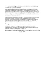
Example (Rope wrapped around a pole): A rope wraps an angle θ around a
pole. You grab one end and pull with a tension T
0
. The other end is attached to a
large object, say, a boat. If the coefficient of static friction between the rope and the
pole is µ, what is the largest force the rope can exert on the boat, if the rope is not
to slip around the pole?
1.2. BALANCING TORQUES I-5
Solution: Consider a small piece of the rope that subtends an angle dθ. Let the
tension in this piece be T (which will vary slightly over the small length). As shown in
Fig. 1.3, the pole exerts a small outward normal force, N
dθ
, on the piece. This normal
T
N
dθ
T
sin
dθ/2
dθ
Figure 1.3
force exists to balance the inward components of the tensions at the ends. These
inward components have magnitude T sin(dθ/2). Therefore, N
dθ
= 2T sin(dθ/2).
The small-angle approximation, sin x ≈ x, then allows us to write this as N
dθ
= T dθ.
The friction force on the little piece of rope satisfies F
dθ
≤ µN
dθ
= µT dθ. This
friction force is what gives rise to the difference in tension between the two ends of
the piece. In other words, the tension, as a function of θ, satisfies
T (θ + dθ) ≤ T(θ) + µT dθ
=⇒ dT ≤ µT dθ
=⇒
dT
T
≤
µ dθ
=⇒ ln T ≤ µθ + C
=⇒ T ≤ T
0
e
µθ
, (1.7)
where we have used the fact that T = T
0
when θ = 0.
The exponential behavior here is quite strong (as exponential behaviors tend to be).
If we let µ = 1, then just a quarter turn around the pole produces a factor of e
π /2
≈ 5.
One full revolution yields a factor of e
2π
≈ 530, and two full revolutions yield a factor
of e
4π
≈ 300, 000. Needless to say, the limiting factor in such a case is not your
strength, but rather the structural integrity of the pole around which the rope winds.
1.2 Balancing torques
In addition to balancing forces in a statics problem, we must also balance torques.
We’ll have much more to say about torque in Chapters 7 and 8, but we’ll need one
important fact here.
Consider the situation in Fig. 1.4, where three forces are applied perpendicularly
F
a b
2
F
1
F
3
Figure 1.4
to a stick, which is assumed to remain motionless. F
1
and F
2
are the forces at the
ends, and F
3
is the force in the interior. We have, of course, F
3
= F
1
+ F
2
, because
the stick is at rest.
Claim 1.1 If the system is motionless, then F
3
a = F
2
(a + b). In other words, the
torques (force times distance) around the left end cancel. And you can show that
they cancel around any other point, too.
We’ll prove this claim in Chapter 7 by using angular momentum, but let’s give a
short proof here.
Proof: We’ll make one reasonable assumption, namely, that the correct relationship
between the forces and distances is of the form,
F
3
f(a) = F
2
f(a + b), (1.8)
I-6 CHAPTER 1. STATICS
where f(x) is a function to be determined.
1
Applying this assumption with the roles
of “left” and “right” reversed in Fig. 1.4, we have
F
3
f(b) = F
1
f(a + b) (1.9)
Adding the two preceding equations, and using F
3
= F
1
+ F
2
, gives
f(a) + f(b) = f (a + b). (1.10)
This equation implies that f(nx) = nf(x) for any x and for any rational number
n, as you can show. Therefore, assuming f(x) is continuous, it must be the linear
function, f(x) = Ax, as we wanted to show. The constant A is irrelevant, because
it cancels in eq. (1.8).
2
Note that dividing eq. (1.8) by eq. (1.9) gives F
1
f(a) = F
2
f(b), and hence
F
1
a = F
2
b, which says that the torques cancel around the point where F
3
is applied.
You can show that the torques cancel around any arbitrary pivot point.
When adding up all the torques in a given physical setup, it is of course required
that you use the same pivot point when calculating each torque.
In the case where the forces aren’t perpendicular to the stick, the claim applies to
the components of the forces perpendicular to the stick. This makes sense, because
the components parallel to the stick have no effect on the rotation of the stick around
the pivot point. Therefore, referring to the figures shown below, the equality of the
torques can be written as
F
a
a sin θ
a
= F
b
b sin θ
b
. (1.11)
This equation can be viewed in two ways:
• (F
a
sin θ
a
)a = (F
b
sin θ
b
)b. In other words, we effectively have smaller forces
acting on the given “lever-arms” (see Fig. 1.5).
F
F
F
a
a
a
a
a
b
b
bb
b
sin
θ
θ
θ
F
sin
θ
Figure 1.5
• F
a
(a sin θ
a
) = F
b
(b sin θ
b
). In other words, we effectively have the given forces
acting on smaller “lever-arms” (see Fig. 1.6).
F
F
a
a
a
a
a
b
b
b
b
b
sin
θ
θ
θ
sin
θ
Figure 1.6
Claim 1.1 shows that even if you apply just a tiny force, you can balance the
torque due to a very large force, provided that you make your lever-arm sufficiently
long. This fact led a well-known mathematician of long ago to claim that he could
move the earth if given a long enough lever-arm.
One morning while eating my Wheaties,
I felt the earth move ‘neath my feeties.
The cause for alarm
Was a long lever-arm,
At the end of which grinned Archimedes!
1
What we’re doing here is simply assuming linearity in F . That is, two forces of F applied at a
p oint should be the same as a force of 2F applied at that point. You can’t really argue with that.
2
Another proof of this claim is given in Problem 12.
1.2. BALANCING TORQUES I-7
One handy fact that comes up often is that the gravitational torque on a stick
of mass M is the same as the gravitational torque due to a point-mass M located at
the center of the stick. The truth of this statement relies on the fact that torque is
a linear function of the distance to the pivot point (see Exercise 7). More generally,
the gravitational torque on an object of mass M may be treated simply as the
gravitational torque due to a force Mg located at the center of mass.
We’ll have much more to say about torque in Chapters 7 and 8, but for now
we’ll simply use the fact that in a statics problem, the torques around any given
point must balance.
Example (Leaning ladder): A ladder leans against a frictionless wall. If the
coefficient of friction with the ground is µ, what is the smallest angle the ladder can
make with the ground and not slip?
Solution: Let the ladder have mass m and length . As shown in Fig. 1.7, we have
N
N
F
mg
θ
l
1
2
Figure 1.7
three unknown forces: the friction force, F , and the normal forces, N
1
and N
2
. And
we fortunately have three equations that will allow us to solve for these three forces:
ΣF
vert
= 0, ΣF
horiz
= 0, and Στ = 0.
Looking at the vertical forces, we see that N
1
= mg. And then looking at the
horizontal forces, we see that N
2
= F . So we have quickly reduced the unknowns
from three to one.
We will now use Στ = 0 to find N
2
(or F). But first we must pick the “pivot” point
around which we will calculate the torques. Any stationary point will work fine,
but certain choices make the calculations easier than others. The best choice for the
pivot is generally the point at which the most forces act, because then the Στ = 0
equation will have the smallest number of terms in it (because a force provides no
torque around the point where it acts, since the lever-arm is zero).
In this problem, there are two forces acting at the bottom end of the ladder, so this is
the best choice for the pivot.
3
Balancing the torques due to gravity and N
2
, we have
N
2
sin θ = mg(/2) cos θ =⇒ N
2
=
mg
2 tan θ
. (1.12)
This is also the value of the friction force F. The condition F ≤ µN
1
= µmg therefore
becomes
mg
2 tan θ
≤ µmg =⇒ tan θ ≥
1
2µ
. (1.13)
Remarks: The factor of 1/2 in this answer comes from the fact that the ladder behaves
like a point mass located halfway up. As an exercise, you can show that the answer for the
analogous problem, but now with a massless ladder and a person standing a fraction f of
the way up, is tan θ ≥ f/µ.
Note that the total force exerted on the ladder by the floor points up at an angle given by
tan β = N
1
/F = (mg)/(mg/2 tan θ) = 2 tan θ. We see that this force does not point along
the ladder. There is simply no reason why it should. But there is a nice reason why it
should point upward with twice the slope of the ladder. This is the direction that causes the
lines of the three forces on the ladder to be concurrent, as shown in Fig. 1.8 .
N
F
mg
2
floor
θ
Figure 1.8
3
But you should verify that other choices for the pivot, for example, the middle or top of the
ladder, give the same result.
I-8 CHAPTER 1. STATICS
This concurrency is a neat little theorem for statics problems involving three forces. The
pro of is simple. If the three lines weren’t concurrent, then one force would produce a nonzero
torque around the intersection point of the other two lines of force.
4
♣
Statics problems often involve a number of decisions. If there are various parts
to the system, then you must decide which subsystems you want to balance the
forces and torques on. And furthermore, you must decide which point to use as the
origin for calculating the torques. There are invariably many choices that will give
you the information you need, but some will make your calculations much cleaner
than others (Exercise 11 is a good example of this). The only way to know how to
choose wisely is to start solving problems, so you may as well tackle some. . .
4
The one exception to this reasoning is where no two of the lines intersect; that is, where all
three lines are parallel. Equilibrium is certainly possible in such a scenario, as we saw in Claim 1.1.
Of course, you can hang onto the concurrency theorem in this case if you consider the parallel lines
to meet at infinity.
1.3. EXERCISES I-9
1.3 Exercises
Section 1.1 Balancing forces
1. Pulling a block
*
A person pulls on a block with a force F , at an angle θ with respect to the
horizontal. The coefficient of friction between the block and the ground is µ.
For what θ is the F required to make the block slip a minimum?
2. Bridges
**
(a) Consider the first bridge in Fig. 1.9, made of three equilateral triangles
m
m
Figure 1.9
of beams. Assume that the seven beams are massless and that the con-
nection between any two of them is a hinge. If a car of mass m is located
at the middle of the bridge, find the forces (and specify tension or com-
pression) in the beams. Assume that the supports provide no horizontal
forces on the bridge.
(b) Same question, but now with the second bridge in Fig. 1.9, made of seven
equilateral triangles.
(c) Same question, but now with the general case of 4n −1 equilateral trian-
gles.
3. Keeping the book up
*
The task of Problem 4 is to find the minimum force required to keep a book
up. What is the maximum allowable force? Is there a special angle that arises?
Given µ, make a rough plot of the allowed values of F for −π/2 < θ < π/2.
4. Rope between inclines
**
A rope rests on two platforms that are both inclined at an angle θ (which you
are free to pick), as shown in Fig. 1.10. The rope has uniform mass density,
θθ
Figure 1.10
and its coefficient of friction with the platforms is 1. The system has left-right
symmetry. What is the largest possible fraction of the rope that does not
touch the platforms? What angle θ allows this maximum value?
5. Hanging chain
**
A chain of mass M hangs between two walls, with its ends at the same height.
The chain makes an angle of θ with each wall, as shown in Fig. 1.11. Find
M
θθ
Figure 1.11
the tension in the chain at the lowest point. Solve this by:
(a) Considering the forces on half of the chain. (This is the quick way.)
(b) Using the fact that the height of a hanging chain is given by y(x) =
(1/α) cosh(αx), and considering the vertical forces on an infinitesimal
piece at the bottom. (This is the long way.)
I-10 CHAPTER 1. STATICS
Section 1.2: Balancing torques
6. Direction of the force
*
A stick is connected to other parts of a system by hinges at its ends. Show
that if the stick is massless, then the forces it feels at the hinges are directed
along the stick; but if the stick has mass, then the forces need not point along
the stick.
7. Gravitational torque
*
A horizontal stick of mass M and length L is pivoted at one end. Integrate
the gravitational torque along the stick (relative to the pivot), and show that
the result is the same as the torque due to a mass M located at the center of
the stick.
8. Tetherball
*
A ball is held up by a string, as shown in Fig. 1.12, with the string tangent
θ
µ
Figure 1.12
to the ball. If the angle b etween the string and the wall is θ, what is the
minimum coefficient of static friction between the ball and the wall, if the ball
is not to fall?
9. Ladder on a corner
*
A ladder of mass M and length L leans against a frictionless wall, with a
quarter of its length hanging over a corner, as shown in Fig. 1.13. Assuming
M
L
θ
1/4 of the
length
Figure 1.13
that there is sufficient friction at the corner to keep the ladder at rest, what
is the total force that the corner exerts on the ladder?
10. Stick on a corner
*
You hold one end of a stick of mass M and length L. A quarter of the way
up the stick, it rests on a frictionless corner of a table, as shown in Fig. 1.14.
hand
M
L
θ
Figure 1.14
The stick makes an angle θ with the horizontal. What is the magnitude of the
force your hand must apply, to keep the stick in this position? For what angle
is the vertical component of your force equal to zero?
11. Two sticks
**
Two sticks, each of mass m and length , are connected by a hinge at their
top ends. They each make an angle θ with the vertical. A massless string
connects the bottom of the left stick to the right stick, perpendicularly, as
shown in Fig. 1.15. The whole setup stands on a frictionless table.
θ θ
m m
l l
string
Figure 1.15
(a) What is the tension in the string?
(b) What force does the left stick exert on the right stick at the hinge? Hint:
No messy calculations required!
1.3. EXERCISES I-11
12. Two sticks and a wall
**
Two sticks are connected, with hinges, to each other and to a wall. The bottom
stick is horizontal and has length L, and the sticks make an angle of θ with
each other, as shown in Fig. 1.16. If both sticks have the same mass per unit
θ
L
Figure 1.16
length, ρ, find the horizontal and vertical components of the force that the
wall exerts on the top hinge, and show that the magnitude goes to infinity for
both θ → 0 and θ → π/2.
5
13. Stick on a circle
**
Using the result from Problem 16 for the setup shown in Fig. 1.17, show that
θ
R
Figure 1.17
if the system is to remain at rest, then the coefficient of friction:
(a) between the stick and the circle must satisfy
µ ≥
sin θ
(1 + cos θ)
. (1.14)
(b) between the stick and the ground must satisfy
6
µ ≥
sin θ cos θ
(1 + cos θ)(2 − cos θ)
. (1.15)
5
The force must therefore achieve a minimum at some intermediate angle. If you want to go
through the algebra, you can show that this minimum occurs when cos θ =
√
3 − 1, which gives
θ ≈ 43
◦
.
6
If you want to go through the algebra, you can show that the maximum of the right-hand side
occurs when cos θ =
√
3 − 1, which gives θ ≈ 43
◦
. (Yes, I did just cut and paste this from the
previous footnote. But it’s still correct!) This is the angle for which the stick is most likely to slip
on the ground.
I-12 CHAPTER 1. STATICS
1.4 Problems
Section 1.1: Balancing forces
1. Hanging mass
A mass m, held up by two strings, hangs from a ceiling, as shown in Fig. 1.18.
T
T
m
2
θ
1
Figure 1.18
The strings form a right angle. In terms of the angle θ shown, what is the
tension in each string?
2. Block on a plane
A block sits on a plane that is inclined at an angle θ. Assume that the friction
force is large enough to keep the block at rest. What are the horizontal
components of the friction and normal forces acting on the block? For what θ
are these horizontal components maximum?
3. Motionless chain
*
A frictionless planar curve is in the shape of a function which has its endpoints
at the same height but is otherwise arbitrary. A chain of uniform mass per
unit length rests on the curve from end to end, as shown in Fig. 1.19. Show,
Figure 1.19
by considering the net force of gravity along the curve, that the chain will not
move.
4. Keeping the book up
*
A book of mass M is positioned against a vertical wall. The coefficient of
friction between the book and the wall is µ. You wish to keep the book from
falling by pushing on it with a force F applied at an angle θ with respect to
the horizontal (−π/2 < θ < π/2), as shown in Fig. 1.20. For a given θ, what
θ
µ
M
F
Figure 1.20
is the minimum F required? What is the limiting value of θ, below which
there does not exist an F that will keep the book up?
5. Objects between circles
**
Each of the following planar objects is placed, as shown in Fig. 1.21, between
L
L
θ
θ
θ
R
F
F
Figure 1.21
two frictionless circles of radius R. The mass density of each object is σ, and
the radii to the points of contact make an angle θ with the horizontal. For
each case, find the horizontal force that must be applied to the circles to keep
them together. For what θ is this force maximum or minimum?
(a) An isosceles triangle with common side length L.
(b) A rectangle with height L.
(c) A circle.