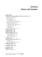
Sensors and actuators chủ đề temperature sensors
Bạn đang xem bản rút gọn của tài liệu. Xem và tải ngay bản đầy đủ của tài liệu tại đây (2.39 MB, 18 trang )
<span class="text_page_counter">Trang 1</span><div class="page_container" data-page="1">
TRƯỜNG ĐẠI HỌC SƯ PHẠM KỸ THUẬT TP.HỒ CHÍ MINH
<b>VIỆN SƯ PHẠM KĨ THUẬT</b>
MƠN HỌC: SENSORS AND ACTUATORS
<i>CHỦ ĐỀ:</i>
<b>TEMPERATURE SENSORS</b>
<small>SVTH: BÙI QUANG NGHI-21146030 NGUYỄN THÁI HUÂN-21146 </small>
TP. Hồ Chí Minh, tháng 4 năm 2023
</div><span class="text_page_counter">Trang 2</span><div class="page_container" data-page="2"><b>1.What is a temperature sensors?</b>
A sensor that is used to measure or maintain a fixed temperature in any device is known as a temperature sensor. This kind of sensor plays a key role in different applications. Physical measurement like temperature is the most common one in industrial-based applications. A temperature sensor provides temperature measurement within a clear form using an electrical signal.
These kinds of sensors are available in various forms, which are utilized for various temperature management techniques. The temperature sensor working mainly depends on the voltage across the terminals of the diode. So, the temperature change is directly proportional to the resistance of the diode.
The measurement of resistance across the terminals of the diode can be done and to change the readable temperature units like Celsius, Fahrenheit, Centigrade & exhibited in the form of numeric over readout units. In the field of geotechnical monitoring, temperature sensors are utilized to calculate the inner temperature of different structures such as buildings, dams, bridges, power plants, etc.
<b>2.Temperature Sensor Circuit:</b>
The circuit diagram of the relay switch using the temperature sensor is shown below. Once the circuit gets the heat then the relay will trigger the load. Any voltage can be applied to this relay like 110V AC or 220V AC or DC appliance so that we can control it routinely on the preferred temperature. This circuit is simple and cheap to build. For electronics beginners, it is a perfect circuit.
</div><span class="text_page_counter">Trang 3</span><div class="page_container" data-page="3">The required components to make this temperature sensor circuit are 9V input DC supply DC, 10KΩ thermistor, transistor BC547B, 6V relay, 1N4007 diode & 20KΩ variable resistor. The operating of this circuit can be done with a 9V battery, an adapter, or a transformer. This circuit includes 2- BC547B transistors like a Darlington pair. So the circuit sensitivity, as well as gain, can be increased through these transistors. The required range of heat can be adjusted using a variable resistor at which you desire to activate your relay. In this circuit, a thermistor plays a key role because it detects heat. This circuit working is quite simple. Once the thermistor gets heat then its resistance will be reduced and it allows the flow of current to activate the transistors.
Once both the transistors are triggered then they allow the voltage toward the relay to activate. So now, the load which is connected to this relay will be activated. This circuit is very useful like operating the fan at the preferred temperature. It activates an alarm in emergencies where you don’t want to overheat.
</div><span class="text_page_counter">Trang 4</span><div class="page_container" data-page="4"><b>3.Types of temperature sensors and working principles of each types:</b>
For all types of temperature sensors, there are two factors that directly affect the accuracy, which is the ambient temperature to be measured and the sensor's perceived temperature. That means the heat transfer from the environment to the tip. The less the temperature sensor's measurement loss, the more accurate the sensor is. This depends largely on the material that makes up the sensor element (expensive or cheap temperature sensor is also determined by this reason). A principle is given when using a thermal sensor that is: must always ensure the heat exchange between the medium to be measured and the sensing element. In terms of general construction, thermal sensors come in many forms, however, the most popular type of sensor in commercial and industrial applications is usually housed in a stainless steel frame, connected to a measuring element. position, with connectors for measuring devices. Some types of sensors are being used quite commonly on the market,
+Firemeter and radiation thermometer
+There is also non-contact, infrared, laser thermal measurement
</div><span class="text_page_counter">Trang 5</span><div class="page_container" data-page="5"><b>3.1.Resistance Temperature Detector(RTD)</b>
- Structure: RTD can be made up of platinum, copper, nickel, semiconductor wire ... wrapped on an insulated core placed in a metal case with the end connected outward.
RTD can use any measuring circuit to measure resistance, but usually used unbalanced bridge circuit, the indicator is the magnetic logommeter electric or equilibrium automatic bridge, where one branch is a
resistance temperature detector
- Classification: metal resistors, semiconductor resistors and thermistors. -Principle: the resistance of a conductor changes with temperature:
cross-section [m2]
Ρ : resistivity [Ωm]
</div><span class="text_page_counter">Trang 6</span><div class="page_container" data-page="6">The dependence of resistance on temperature is almost linear represented by the equation
This expression is for huge range of temperature. For small range of temperature, the expression can be,
a, b, α : Metal-dependent constant
R(t): resistance at the temperature to be measured T [°K] R(o): resistance at temperature To[°K]
-Effects of self-heating :
δ : power dissipation factor [mW/ °C] PD : power dissipation [mW]
</div><span class="text_page_counter">Trang 7</span><div class="page_container" data-page="7">-Sensitivity [Ω/ °C]
If the temperature increases, the resistance increases ●Advantages: Durable, high temperature measurement.
●Disadvantages: Many influencing factors make the error. Not very sensitive
</div><span class="text_page_counter">Trang 8</span><div class="page_container" data-page="8">●Commonly used: Heat furnace, harsh environment, compressor viscosity heat measurement,... Range measurement: -100 D.C <1400 D.C
The method of measuring temperature with a stochastic thermocouple is one of the methods the most popular and favorable.
*Structure and principle of operation of thermocouple thermometer: consists of two wires welded together at point 1 and threaded into tube 2 to be able to measure high temperature. With a lower temperature, the thermometer housing can be made of stainless steel. To insulate between two wires, one of the two wires is nested into a small porcelain tube 3.If the shell doesmetal both wires are placed in porcelain tube.
</div><span class="text_page_counter">Trang 9</span><div class="page_container" data-page="9">- The output of the thermocouple is connected to the terminal box 4. The measuring circuit of the thermocouple thermometer is milliVolmeters or a small resistance potentiometer with a measuring range from 0÷100mV. - If measuring the thermoelectric power in millivoltmeters, it will cause errors because the temperature of the measuring circuit changes. The current flowing through the indicator at that time is:
- The voltage drop per millivoltmeter is:
Usually R + R is calibrated to about 5 , while the resistance of<small>dT</small>
milliVolmeters is many times larger (40÷50 times), so the error is mainly due to electricity resistance of millivoltmeter R changes.<small>dc</small>
</div><span class="text_page_counter">Trang 10</span><div class="page_container" data-page="10">- Measuring the electromotive force with a potentiometer will eliminate the above error due to currentconsumption is zero when we take the measurement
When two metals with different work functions come together, a voltage is created at the junction. This voltage is proportional to the temperature, and this junction is referred to as a “thermocouple.”
The thermocouple operates on three effects including the “Seebeck effect”, the “Peltier effect”, and the “Thomson effect”.
<b>3.2.1.Seebeck effect:</b>
A physicist named “Thomas Seebeck” discovered in 1821 that when two distinct metal wires are linked in a circuit at both ends of a junction, the temperature applied to the junction equals the current flowing through the circuit. It is referred to as the electromagnetic field (EMF). The energy produced by this circuit is referred to as the Seebeck effect. The quantity of induced EMF varies with metal combination and is related to the temperature differential between the junctions. This is the fundamental functioning principle of a thermocouple. In a nutshell, it is a phenomenon in which the temperature differential between two metals causes potential differences between them.
</div><span class="text_page_counter">Trang 11</span><div class="page_container" data-page="11"><b>3.2.2.Peltier effect:</b>
The Peltier effect is an important part of the thermocouple’s operation. This effect is the polar opposite of the See beck effect. The Peltier effect demonstrates that by introducing a potential difference between two distinct types of conductors, a temperature differential may be generated. The thermocouple circuit is made up of two metals that are linked together to produce two temperature junctions. The difference in temperatures between the circuit’s two junctions generates a Peltier EMF. The total EMF within the circuit may be calculated using the junction temperature and the characteristics of the metals employed in the circuit. A body with an unknown temperature is attached to one of the circuit’s connections, known as the hot junction. Another body with a known temperature is linked to the other connection, which is known as the cold or reference junction. To directly measure the voltage or current output from the thermocouple circuit, a voltmeter is attached to the thermocouple circuit.
<b>3.2.3.Thomson effect:</b>
As the temperature of the junction varies, so does the voltage, which may be monitored using an electronic controller’s input circuits. The
</div><span class="text_page_counter">Trang 12</span><div class="page_container" data-page="12">voltage output is related to the temperature difference between the junction and the free ends. This is known as the Thompson effect. According to this effect, when two dissimilar metals are linked together to form two junctions, a potential occurs inside the circuit owing to a temperature gradient throughout the whole length of the conductors within the circuit. In most situations, the EMF predicted by the Thomson effect is relatively tiny and may be ignored by carefully selecting metals.
●Advantages: + Durable + Can measure high temperature + Easy to use
●Disadvantages: + Many factors affect the error + Sensitivity is not high
Application: + Heat furnace●
</div><span class="text_page_counter">Trang 13</span><div class="page_container" data-page="13">+ Harsh environment
+ Measure compressor oil temperature + Measuring range: -100DC < 1400DC
<b>-Construction:</b>A thermistor is made of oxides of metals such as Nickel, Manganese, Cobalt, Copper, Uranium etc. It is available in a variety of shapes and sizes. Commonly used for configurations are Disk type, Bead type and Rod type.
The disc type thermistor and rod type thermistor is used when greater power dissipation is required. The rod type thermistor has high power handling capacity.
The smallest thermistor in these configurations is the bead type thermistor. its diameter is low as 0.15 mm. The measurement element is typically encapsulated in a glass probe. It is commonly used for measuring the temperature of liquids.
*Working principle of Thermistor:The resistance of the thermistor changes with change in thermistor body temperature. The resistance of
</div><span class="text_page_counter">Trang 14</span><div class="page_container" data-page="14">the thermistor does not vary linearly with change in temperature. The thermistor has non-linear resistance temperature curve. The resistance of the thermistor can be measured using resistance meter(Ohm-meter). By knowing the exact relationship between the change in the resistance with temperature,the temperature can be derived by measuring the resistance of thermistor at particular temperature. The change in the thermistor resistance with temperature depends on the type of material used for thermistor construction. The plot between temperature and resistance of a thermistor is as given below.
From above graph we can measure the temperature by measuring the resistance of the thermistor. The procedure of temperature measurement is as follows.
●Measure the resistance of the thermistor by Ohm-meter.
●Draw a vertical line across from the resistance on the y-axis and drawing a vertical line down from where this horizontal line intersects with the graph, we can hence derive the temperature.
</div><span class="text_page_counter">Trang 15</span><div class="page_container" data-page="15">-Types of thermistor:
The thermistors are classified according to increase or decrease in thermistor resistance with variation in temperature. There are two types of thermistors.
+Negative Temperature Coefficient (NTC) Thermistor +Positive Temperature Coefficient (PTC) Thermistor
<b>3.3.1.NTC Thermistor</b>
NTC thermistor has negative temperature coefficient and the resistance of the thermistor decrease with an increase in the temperaure and, the thermistor resiatnce increase when temperature decrease. Thus, the resistance and temperature are inversely proportional in NTC thermistor. The electric current flow tthrough the NTC thermistor increase with increase in temperature.
With increase in temperature, a large number of charge carriers or free electron collides with valence electron of other atom.The valence electrons which gains sufficient energy will breaks the bonding with the parent atom and moves freely from one place to another place. The electrons that move freely from one place to another place are called free electrons. Thus, the free electrons increase due to rapid collision of the free electrons with the atom.The small increase in temperature produce millions of free electrons. The more free electrons cause rapid increase in electric current. Thus, the small increase in temperature cause rapid decrease in the temperature and allows a large current flow through the thermistor.
</div><span class="text_page_counter">Trang 16</span><div class="page_container" data-page="16">The resistance of NTC thermistor decrease with an increase in temperature. The relationship between the temperature and resistance is governed in NTC thermistor by the following mathematical expression.
The equation of the thermistor is highly non linear. A standard NTC thermistor usually exhibits a negative thermal resistance temperature coefficient of about 0.0045/oK
The Beta (β) value of a thermistor is an indicator of the slope of the resistance-temperature curve characteristic.
The Beta (β) value of a thermistor is an indicator of the slope of the resistance-temperature curve characteristic.
</div><span class="text_page_counter">Trang 17</span><div class="page_container" data-page="17">The higher value β shows good relationship between the resistance and temperature. For small increase in temperature will cause more decrease in the resistance if value of β is high. Thus higher sensitivity and more accuracy can be achieved if the value of β is high.
From equation (1) the temperature coefficient of the thermistor can be given as;
The equation (2) shows that the thermistor has negative temperature coefficient.
If β= 4000 K and T = 298 K, then the αT = 0.0045/ K temperature∘ coefficient. The temperature coefficient of the thermistor is much higher than the sensitivity of the platinum RTD.
<b>3.3.2.PTC Thermistor:</b>
The resistance of the PTC thermistor increase with increase in
temperature. The PTC thermistors are made from doped polycrystalline ceramic. Thermistors with Positive Temperature Co-efficient (PTC) are also called posistors. The plot between resistance and temperaure of PTC thermistor is as given below.
</div><span class="text_page_counter">Trang 18</span><div class="page_container" data-page="18">The PTC thermistors are not as popular as NTC thermistors. The PTC thermistors are used in circuit protection. When current pass through PTC thermistor, it cause heating.In a PTC thermistor, this heating up will also cause increase in resistance. This creates a self-reinforcing effect that drives the resistance upwards, therefore limiting the current and thus PTC thermistor is used as a current limiting device.
</div>