Process report research and testing anti lock braking system and traction control system of honda civic 2020 by matlab and carsim software
Bạn đang xem bản rút gọn của tài liệu. Xem và tải ngay bản đầy đủ của tài liệu tại đây (21.58 MB, 102 trang )
<span class="text_page_counter">Trang 1</span><div class="page_container" data-page="1">
<b>FACULTY FOR HIGH QUALITY TRAINING</b>
<b>PROCESS REPORT</b>
<b>RESEARCH AND TESTING ANTI LOCK BRAKINGSYSTEM AND TRACTION CONTROL SYSTEM OF</b>
<b>HONDA CIVIC 2020 BY MATLAB AND CARSIMSOFTWARE</b>
Ho Chi Minh City, June 2022
</div><span class="text_page_counter">Trang 2</span><div class="page_container" data-page="2"><b>FACULTY FOR HIGH QUALITY TRAINING</b>
<b>PROCESS REPORT</b>
<b>RESEARCH AND TESTING ANTI LOCK BRAKINGSYSTEM AND TRACTION CONTROL SYSTEM OF</b>
<b>HONDA CIVIC 2020 BY MATLAB AND CARSIMSOFTWARE</b>
</div><span class="text_page_counter">Trang 3</span><div class="page_container" data-page="3">Student name: __________________________ Student ID: ___________________ Student name: __________________________ Student ID: ___________________ Student name:___________________________ Student ID: ___________________ Major: ________________________________ Class: ________________________
Advisor: ____________________________ Phone number: _________________ Date of assignment: _____________________ Date of submission: _____________ 1. Project title: _________________________________________________________ 2. Initial materials provided by the advisor: ___________________________________ 3. Content of the project: _________________________________________________ 4. Final product: ________________________________________________________
<b>CHAIR OF THE PROGRAM</b>
(Sign with full name)
(Sign with full name)
</div><span class="text_page_counter">Trang 4</span><div class="page_container" data-page="4"><b>ADVISOR’S EVALUATION SHEET</b>
Student name:______________________________ Student ID:_____________ Major: Automotive Engineering
Project title: Research and Testing the Anti Lock Braking System and Traction Control System on Honda Civic 2020 by MATLAB and Carsim Software
THE SOCIALIST REPUBLIC OF VIETNAM
<b>Independence – Freedom– Happiness</b>
---Ho Chi Minh City, June 12, 2022
</div><span class="text_page_counter">Trang 5</span><div class="page_container" data-page="5"><b>The authors gratefully acknowledge the valuable supports from Ph.D. Nguyen Manh </b>
<b>Cuong from Ho Chi Minh City University of Technology and Education.</b>
</div><span class="text_page_counter">Trang 6</span><div class="page_container" data-page="6"><b>CHAPTER I: OVERVIEW OF CAR BRAKE SYSTEM</b>
<b>1. Purpose and meaning of the topic</b>Currently, cars have become an important means of transporting passengers and goods for national economic sectors, and at the same time have become a private means of transport in countries with developed economies. In our country, the number of people using cars is increasing, along with the growth of the economy, the increasing density of cars on the road leads to more and more traffic accidents. Therefore, to ensure the safety of traffic accidents is one of the most necessary solutions, always concerned by the designers and manufacturers of cars, where the brake system plays a very important role. Because of that, now the brake system is increasingly improved, the standards for the design, manufacture and use of the brake system are increasingly strict and strict. For students majoring in traffic mechanics, the survey and testing of the brake system is even more practical. That's why I chose the topic "Surveying, calculating and testing the ABS brake system on Honda Civic 2020". To solve this problem, first of all, we need to understand the operating principle, structure of details and parts in the brake system. Thereby creating a premise for the design and improvement of the brake system to increase braking efficiency, increase directional stability and guideability when braking, increase working reliability for the purpose of ensuring movement safety and increasing safety. vehicle performance.
<small>2.</small> <b>Uses, classifications and requirements of the brake system.</b>
<small>2.1</small> <b>Uses</b>
The brake system is used to slow down the vehicle until it comes to a complete stop or
</div><span class="text_page_counter">Trang 7</span><div class="page_container" data-page="7"><small>+</small> Brake clogs
<small>+</small> Brakes
<small>+</small> Disc brake
- Classification by mode of drive
<small>+</small> Mechanical brake drive
<small>+</small> Hydraulic brake drive
<small>+</small> Pneumatic (vapor) brake drive
<small>+</small> Combined brake drive (hydraulic + pneumatic)
<b><small>+</small></b> Power-assisted brake drive
<small>2.3</small> <b>Requirements</b>
The brake system is an important part of the car that performs "active safety" functions, so the brake system must satisfy the following requirements:
<small>+</small>Has the highest braking efficiency on all wheels under all circumstances
<small>+</small>Quiet operation to ensure the stability of the car when braking
<small>+</small>Smooth control to reduce the driver's labor intensity
<small>+</small>Has high sensitivity to quickly adapt to dangerous situations
<small>+</small>The brake mechanism has no self-tightening phenomenon
<small>+</small>The brake mechanism must have good heat dissipation
<small>+</small>Has a high and stable coefficient of friction
<small>+</small>Keeping the ratio between the force applied to the brake pedal and the braking force generated by the brake mechanism
<small>+</small>The system must have reliability, durability and long life
<small>+</small>Streamlined layout for easy adjustment of care and maintenance
<small>3.</small> <b>Structure of disc brakes</b>
Disc brake mechanism is commonly used on passenger cars (mainly on the front wheels). Recently, this type of brake began to be used on some types of transport and passenger cars.
Disc brakes are of the following types: closed, open, single disc, multi-disc, rotating housing type, rotating disc, rotating friction ring.
The disc can be a solid disc, a disc with vented slots, a single layer of metal, or a composite of two dissimilar metals. In automobiles, the main type of open disc is used, and rarely the rotary shell type is used.
There are two mounting options for clamps: fixed mounting and optional swimming style mounting. Fixed mounting plan has high rigidity, allowing large driving force to be used. However, the cooling condition is poor, and the working temperature of the brake mechanism is higher.
</div><span class="text_page_counter">Trang 9</span><div class="page_container" data-page="9">stiffness. When the guide pins are deformed, wear and tear will cause the brake pads to wear unevenly, reduce the braking efficiency and cause vibration. However, it has only one hydraulic cylinder with twice the length, so the cooling condition is better, the brake fluid is less hot, the working temperature can be reduced by 30 ÷ 50 ˚C. In addition, it also allows deep translation of the brake mechanism into the wheel. Thereby reducing the lever arm acting on the rolling resistance to the vertical cylinder of the guide wheels.
Figure 2 Structural diagram of disc brake with automatic clamp type - fixed cylinder: <small>1.</small> Brake Pads 5. Guide Pin
<small>2.</small> Fixed Clamp 6. Locating Gauze
<small>3.</small> Piston 7. Brake Disc
</div><span class="text_page_counter">Trang 10</span><div class="page_container" data-page="10"><small>4.</small> Sealing Ring 8. Shock Absorber Ring
</div><span class="text_page_counter">Trang 11</span><div class="page_container" data-page="11"><small>4.</small> Sealing Ring 8. Ventilation Grooves 9. Brake Disc
<b><small>-</small>Advantages of disc brake mechanism compared with drum-hoop brakemechanism</b>
<small>+</small> Able to work with a small gap of 0.05 ÷ 0.15 mm, so it is very sensitive, reduces the delay time and allows to increase the gear ratio.
<small>+</small> The pressure is evenly distributed over the surface of the brake pads, so the brake pads wear evenly.
<small>+</small> Simple maintenance since no clearance adjustment is required.
<small>+</small> The axial and self-balancing forces should allow their values to be increased to achieve the required braking effect without being limited by the deformation conditions of the structure. Therefore, disc brakes are compact in size and easy to arrange in the wheel.
<small>+</small> The braking effect is independent of rotation direction and more stable.
<small>+</small> Better cooling conditions, especially with the rotating disc type.
<b><small>-</small>Disadvantages of disc brake mechanism compared to drum-hoo brakemechanism:</b>
<small>+</small> Sensitive to dirt and difficult to seal.
<small>+</small> Open type brake discs are easily oxidized and dirty, causing the brake pads to wear quickly.
<small>+</small> High working pressure makes the brake pads easy to crack and scratch.
<small>+</small> It is often necessary to use vacuum boosters to increase driving force, so when the engine is not working effectively, the brake performance is low and it is difficult to use them to combine as a stop brake.
<b><small>-</small>Structural characteristics of the main details and parts:</b>
<small>+</small> Brake disc: usually made of cast iron. Solid discs are 8 - 13 mm thick. Ventilated slotted disc 16 - 25 mm thick. The coupling disc can have an aluminum or copper core and a friction surface – gray cast iron.
<small>+</small> Clamp: usually cast in wrought iron.
<small>+</small> Hydraulic cylinders: cast aluminum alloy. To increase wear resistance and reduce friction, the working surface of the cylinder is chrome plated. When the cylinder is made of aluminum alloy, it is necessary to reduce the heating temperature of the brake fluid. One of the ways to reduce the temperature of brake fluid is to reduce the contact area between the piston and the brake shoe or to use pistons made of non-metallic materials.
<small>+</small> Brake pad bodies: the place where the piston presses up is made of sheet steel.
<small>+</small> Friction plate: of open disc brake pads usually have a surface area of about 12 -16% of the disc surface area, so disc cooling conditions are very favorable.
</div><span class="text_page_counter">Trang 12</span><div class="page_container" data-page="12"><b>4.1 Causes</b>
One of the most common causes of “brake failure” accidents is a loss of brake fluid pressure. The brake is operated by hydraulic pressure inside the system. Therefore, if there is a leak of brake fluid in the brake fluid line or brake cylinder, the brake system will not have enough pressure to perform the deceleration. When a serious leak occurs, the brake fault light will light up to warn you and the vehicle will not be safe to operate in this condition.
Check the brake fluid tank, if the oil level is too low, it means there is a serious brake fluid leak, need to check the entire brake system to find out where the leak is and fix it. Leaks have many causes, but if the brake fluid level is too low, it means that the rubber seal in the brake system is broken or the oil line is rusty.
</div><span class="text_page_counter">Trang 13</span><div class="page_container" data-page="13">If the brake pedal is not effective, there may be air in the system. At this time, it is necessary to vent the brake system to remove air bubbles. Sometimes it can also be because the piston inside the master cylinder is damaged.
Figure 5: Low oil pressure indicator light
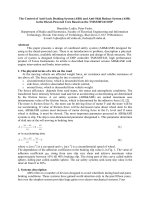
Another possible cause of brake failure is a faulty ABS controller. Due to the leak, the internal pressure drops and the brake pressure cannot be transferred when the brake is applied. Contamination inside the brake fluid can also enter the control unit and prevent the intake and exhaust valves from opening and closing, causing the brakes to fail.
</div><span class="text_page_counter">Trang 14</span><div class="page_container" data-page="14">Figure 6: When the ABS controller fails, the light will warn
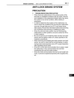
The cause of brake failure can also be caused by the driver, that is, pressing the brakes continuously for a long time (usually when the vehicle is going downhill on a pass) causes the brake pads to burn, leading to ineffective braking. To avoid this, the driver should not apply the brakes for a long time, instead can use the engine to reduce the vehicle's speed (by engaging in low gear).
</div><span class="text_page_counter">Trang 15</span><div class="page_container" data-page="15">Some unexpected accidents related to brake failure, loss of control
Figure 8: The bus lost its brakes and rolled many motorbikes at the red light
</div><span class="text_page_counter">Trang 16</span><div class="page_container" data-page="16">Figure 9 : Passenger car lost the brake
The brake is the part that helps the vehicle decelerate to reduce motion. However, after many accidents, the question often arises, why does the brake lose its effect? Is it
</div><span class="text_page_counter">Trang 17</span><div class="page_container" data-page="17">directional stability and guideability when braking, increase working reliability for the purpose of ensuring movement safety and increasing safety. vehicle performance. It is for these reasons that I have chosen this topic.
<b>CHAPTER II: INTRODUCE ABOUT HONDA CIVIC 2020</b>
1.
<b>The Overall of Honda Civic 2020</b>In the Vietnamese market, the Honda Civic model right after its launch has always received positive feedback from consumers. Over 10 generations, this small sports C-class sedan has quickly entered the list of Top 10 best-selling cars of all time, Honda Civic has become a typical representative of Honda, in terms of agility, in terms of flexibility and especially in terms of reliability.
Figure 10: The exterior appearance of the Honda Civic 2020
Unconventional styling with solid lines but still emotional flexibility along with high-class details, gives Civic a youthful, modern and sportier appearance than ever. In particular, the aerodynamic design style also helps to complete the fuel efficiency and quietness of the cabin.
</div><span class="text_page_counter">Trang 18</span><div class="page_container" data-page="18">This is the most spectacular makeover ever of this small sedan. With an all-new fastback design, the most powerful turbo engine in the segment, and many safety-driving assist technologies are notable points in this version.
In Vietnam, Honda Civic is being distributed with 03 versions, which are the standard Civic 1.8E CVT with naturally aspirated gas, the turbocharged Civic 1.8G CVT and the high-end Civic 1.5RS CVT Turbo.
<b>2.</b>
<b>Honda Civic Overview</b><small>2.1</small> <b>Overview of Honda Civic cars</b>
</div><span class="text_page_counter">Trang 19</span><div class="page_container" data-page="19"><b>2.2.1 Honda Civic specifications are listed in the table 1</b>
Table 1: Basic technical parameters of Honda Civic 2020
Fuel tank capacity (litre) 47 47 47 Fuel system PGM-FI PGM-FI PGM-FI Acceleration time from 1 to
100km/h (giây) <sup>10</sup> <sup>10</sup> <sup>8.3</sup>
Length x Width X Height (mm) 4.648 x 1.799 x 1.416 The standard long (mm) 2700
Front brake Disc brake Rear brake Disc brake
<b>2.2.2 Engine</b>
</div><span class="text_page_counter">Trang 20</span><div class="page_container" data-page="20">Figure 12: Engine on Honda Civic 2020
The first engine block equipped on the standard versions Civic 1.8E & Civic 1.8G is a naturally aspirated 1.8 SOHC i-VTEC engine, 4 cylinders, 16 valves. This engine block delivers a maximum power of 139 (hp) at 6,500 rpm (rpm), along with a maximum torque of 174 (Nm) at 4,300 (rpm). Comes with a CVT automatic transmission using Honda's Earth Dreams technology. In versions 1.8E & 1.8G naturally aspirated with
</div><span class="text_page_counter">Trang 21</span><div class="page_container" data-page="21">must trade off fuel consumption to achieve higher power output. With the same fuel, the VTEC TURBO engine produces more power than a naturally aspirated engine, by reusing energy from the exhaust gas, which increases the thermal efficiency of the engine.
<b>2.2.3 Powertrain, steering system</b>
Exciting driving experience with MA-EPS (Motion Adaptive Electric Power Steering)
Figure 13: Steering system uses electronic power steering ESP
- MA-EPS is a combination of EPS electronic power steering system with VSA . system
- MA-EPS uses data about vehicle speed and steering angle as input signals to analyze, calculate and make adjustments to the steering system.
- Steering force will be gentle when the vehicle is operating at low speed and will be more compact when the vehicle is operating at high speed
- In the following cases: oversteer, understeer, slippery road, MA - EPS makes it easier for the driver to steer the steering wheel in a stable direction & difficult to steer in an unstable direction. This helps the car to be more balanced and safe on all roads.
With EPS and MA-EPS electronic steering system, Honda vehicles will give customers the confidence to operate quickly, accurately and stably during the journey, customers will feel secure and safe. completely when traveling on all roads with a Honda.
</div><span class="text_page_counter">Trang 22</span><div class="page_container" data-page="22">The Honda Civic 2020 brake system is a hydraulic brake system with vacuum assist, using a disc brake mechanism on the front and rear axles. The anti-lock braking system (ABS) combines the electronic brake force distribution system EBD (Electronic Brake Force Distribution) with internal sensors to ensure optimization on all terrains.
</div><span class="text_page_counter">Trang 23</span><div class="page_container" data-page="23">Figure 15: Chassis and suspension system on Honda Civic 2020
- The lighting and signaling system includes: Headlights, turn signals, brake lights, fog lights, license plate lights, ceiling lights in the car, oil pressure indicator lights, battery charge indicator lights, lights. low fuel alarm...
- Ventilation, heating, air conditioning systems, wipers, glass washers... - Sound system: 8-speaker audio, the ability to answer phones hands-free, texting,
voice commands and navigation maps...
</div><span class="text_page_counter">Trang 24</span><div class="page_container" data-page="24"><b>CHAPTER III: Braking system on Honda Civic</b>
<b>3.1 General layout diagram of the brake system on the vehicle</b>Figure 16: General layout diagram of the brake system on the vehicle
</div><span class="text_page_counter">Trang 25</span><div class="page_container" data-page="25">times to avoid the above situation. However, there is no time to do this during emergency braking. To solve the above problem, manufacturers to create cars with ABS system - Anti-lock Braking System.
<b>3.2.2 Diagram of brake system drive</b>
<b>a) General diagram of the main brake system ABS</b>
The anti-lock braking system (ABS) is essentially a brake force regulator with a reverse contact circuit. The typical block diagram of an ABS looks like this:
Figure 17: General diagram of the main brake system ABS 1. Brake disc 8. Hydraulic block 2. Sensor gear ring 9. Signal line 3. Master cylinder 10. ABS indicator light 4. Vacuum booster 11. Rear brake fluid line 5. Pedal 12. Rear wheel speed sensor 6. Front wheel speed sensor 13. Wheel brake cylinder 7. Front brake fluid line
</div><span class="text_page_counter">Trang 26</span><div class="page_container" data-page="26">- When the brake pedal is pressed, the high pressure oil in the master brake cylinder (3) is amplified by the power assist, which will be transmitted to the wheel cylinders and perform the braking process.
- If one of the wheels shows signs of slowing down compared to the other wheels (about to lock), this signal is processed by the ECU and the brake hydraulic control ECU works to reduce the oil pressure in the wheel cylinder. the car so that it doesn't lock up.
- ABS ensures directional stability and control performance during braking
- If there is a fault in the ABS system, the ABS indicator (10) lights up and the check must be carried out through the diagnostic machine.
During ABS control, the wheels involved are controlled by a total of 4 pressure holding valves and 4 pressure reducing valves.
<b>b) Diagram of hydraulic control assembly</b>
</div><span class="text_page_counter">Trang 27</span><div class="page_container" data-page="27">Figure 18: Diagram of hydraulic control assembly
1. Oil pipelines 10. Rubber ring proportional structure 2. Piston master cylinder 11. Power steering membrane 3. Master cylinder 12. Vacuum booster 4. Engine intake manifold 13. Brake fluid reservoir 5. Vacuum valve 14. Front and rear wheel cylinders 6. Air filtration 15. One way valve
7. Pedals 16. Engine intake line 8. Push lever
9. Air valve
<b>Working principle:</b>
The vacuum booster (12) has two compartments A and B separated by a diaphragm (11). Vacuum valve (5) does the job: Connecting two compartments A and B when the brake is released and cutting the passage between them when the brake is applied. The air valve (9), does the job: Cut the passage of compartment A with the atmosphere when the brake is released and open the passage of compartment A when the brake is applied. Rubber ring (10) is a proportional mechanism: It is responsible for ensuring the ratio between pedal force and brake force. The chamber B of the booster bulb is always connected to the engine intake manifold via a check valve (15), so there is a constant
</div><span class="text_page_counter">Trang 28</span><div class="page_container" data-page="28">vacuum. When releasing the brake: The vacuum valve (5) opens, so compartment A will communicate with compartment B through this valve and have the same vacuum pressure. When braking: The driver acts on the pedal to push the lever to move to the right, causing the vacuum valve (5) to close and cut off the passage of two compartments A and B, and the air valve (9) to open to allow air to pass through the filter element. (6) enters compartment A. The pressure difference between two compartments A and B will create a pressure acting on the membrane of the power steering and thereby create an auxiliary force to support the driver and act on the components. piston in the master cylinder (2), presses the oil along the pipes to the wheel cylinders to perform the braking process. When the force acting on the power steering diaphragm (11) increases, the deformation of the rubber ring (10) also increases, causing the piston to move slightly forward relative to the push rod, causing the air valve (9) to close and hold. for a constant differential pressure, i.e. constant power assist. To increase braking force, the driver must continue to pedal harder, push the lever to move to the right to make the air valve (9) open to allow more air to enter compartment A. The pressure difference increases, the rubber ring (10 ) is more deformed, causing the piston to move forward slightly compared to the rod (8), making the air valve (9) close to ensure that the pressure difference or power assist is constant and proportional to the pedal force. When the braking force is at its maximum, the air valve opens completely and the pressure difference or power assist also reaches the maximum value.
<b>3.2.3. Stages of the ABS brake system</b>
Normal braking process
</div><span class="text_page_counter">Trang 29</span><div class="page_container" data-page="29">Figure 19: Diagram of ABS system when braking normally 1. Election of assistants 9. Pulse generating gear 2. Oil pipeline 10. One-way crazy valve 1 3. Non-return valve No. 3 11. Oil pump
4. Coil 12. One-way electric valve 2 5. Pressure holding valve 13. Storage tank
6. Valve pressure relief 14. Battery 7. Brake mechanism 15. ECU slide control 8. Speed sensor
During normal braking, the ABS system does not operate and the ABS-ECU does not send current to the coils of the valves and the pump motor does not operate. Thus open the pressure retaining valve and close the pressure reducing valve and make the valves in the position as shown
</div><span class="text_page_counter">Trang 30</span><div class="page_container" data-page="30">When the brake pedal is pressed, the oil from the master brake cylinder will pass through the pressure-holding valve into the wheel brake cylinder and perform the normal braking process.
When the brake is released, the oil from the wheel brake cylinder will return through the pressure retaining valve to return to the master brake cylinder.
When performing emergency braking (ABS system will work)
If any wheel appears to be about to lock, the ABS-ECU will send a signal to control the brake fluid pressure acting on that wheel cylinder in the direction of pressure reduction to avoid locking.
Normally, the process of controlling brake fluid pressure through 3 stages is:
<b>a) Pressure drop stage</b>
</div><span class="text_page_counter">Trang 31</span><div class="page_container" data-page="31">Figure 20: Diagram of working principle of ABS system (Pressure Reduction Stage) 1. Election of assistants 9. Pulse generating gear
2. Oil pipeline 10. One-way crazy valve 1 3. Non-return valve No. 3 11. Oil pump
4. Coil 12. One-way electric valve 2 5. Pressure holding valve 13. Storage tank
6. Valve pressure relief 14. Battery 7. Brake mechanism 15. ECU slide control 8. Speed sensor
When a wheel is about to lock, based on the signal received from the wheel speed sensor. The ABS-ECU will send electricity (5V) to the coils of the solenoid valves, generating a strong magnetic force that overcomes the elastic force of the valve springs. As a result, the pressure retaining valve closes and the pressure reducing valve opens when the oil from the wheel cylinder will return to the oil tank. At the same time, the
</div><span class="text_page_counter">Trang 32</span><div class="page_container" data-page="32">pump motor continues to run while the ABS is operating thanks to the signal from the ECU, so the brake fluid flowing into the reservoir is sucked by the pump back to the
</div><span class="text_page_counter">Trang 33</span><div class="page_container" data-page="33">When the pressure in the wheel cylinder decreases or increases, the wheel speed sensor sends a signal to the ECU. If the wheel speed is at the desired speed, the ABS-ECU will supply current (5V) to the solenoid valve to keep closing and cut off the current of the pressure reducing valve when
Then the return spring will close the valve, that is, both the pressure retaining valve and the pressure reducing valve are closed. As a result, the oil pressure in the wheel cylinders is kept constant.
<b>c) Pressure rise stage</b>
Figure 22: Diagram of working principle of ABS system (Stage Booster Pressure) 1. Election of assistants 9. Pulse generating gear
2. Oil pipeline 10. One-way crazy valve 1 3. Non-return valve No. 3 11. Oil pump
4. Coil 12. One-way electric valve 2
</div><span class="text_page_counter">Trang 34</span><div class="page_container" data-page="34">5. Pressure holding valve 13. Storage tank 6. Valve pressure relief 14. Battery 7. Brake mechanism 15. ECU slide control 8. Speed sensor
When the pressure in the cylinder of a wheel decreases, its rotation speed increases, there is a speed difference of that wheel (faster) compared to other wheels, the signal from the wheel speed sensor will be sent to the ABS-ECU. ABS-ECU will cut off the current to the pressure retaining valve when both the pressure retaining valve and the pressure reducing valve have a voltage of 0V. As a result, the pressure-retaining valve opens and the pressure-relief valve closes evenly thanks to the return force of the spring, the oil from the master brake cylinder enters the wheel brake cylinder through the pressure retaining valve. At the same time, the pump motor is still operating from the control signal of the ABS-ECU, which supplies oil from the reservoir to the wheel cylinder through the pressure-holding valve, increasing the pressure of the wheel cylinder.
<b>3.3 Structure and and main parts3.3.1 Brake mechanism</b>
All four brake mechanisms working on the vehicle are disc brakes with automatic clamps with Cylinders arranged on the clamps. However, there is a structural difference between the front brake mechanism and the rear brake mechanism.
This type of brake mechanism has a low rigidity, when the guide pins are deformed and worn, the brake pads will wear unevenly, the braking efficiency will be reduced, and there will be large vibrations. However, this type of brake gives better cooling
</div><span class="text_page_counter">Trang 35</span><div class="page_container" data-page="35">Figure 23: Front brake mechanism Honda Civic 1. Brake disc 9. Sealing gasket 16. Dust shield
2. Brake pads 10. Protective cushions 17. Bolts catch wheel hub to brake disc
3. Brake pad body 11. Compartment ring 18. Silver pads
</div><span class="text_page_counter">Trang 36</span><div class="page_container" data-page="36">4. Mobile brake fork 12. Bolts to catch brake
calipers and beams 19. Dust shield ring 5. Air release screw 13. Hole to catch brake
assembly on car girder 20. Brake bolt 6. Cylinder 14. Wheel hubs 21. Rings 7. Piston 15. Ventilation grooves 22. Slide pin 8. Oil supply hole
The friction plate of open disc brake pads usually has a small friction area compared to the disc surface area, so the disc cooling conditions are very favorable. Hydraulic cylinders made of aluminum alloy. To increase wear resistance and reduce friction, the working surface of the cylinder is chrome plated. When the cylinder is made of aluminum alloy, it is necessary to reduce the heating temperature of the brake fluid. One of the ways to reduce brake fluid temperature is to reduce the contact area between the piston and the brake pads or to use pistons made of non-metallic materials. The brake pads where the piston presses against are made of sheet steel. The hydraulic cylinder pressing mechanism, also known as the child cylinder or wheel cylinder, has a simple structure and is easy to arrange. The cylinder body is made of gray cast iron, the working surface is polished. Piston is made of aluminum alloy.
<b>Working principle: When the driver steps on the brake pedal, the oil is pushed from</b>
the master cylinder to the booster, a part directly goes to the wheel cylinders to generate braking force, partly through the duct to open the air valve of the vehicle. the booster creates a pressure difference between the two compartments in the booster. It is that
</div><span class="text_page_counter">Trang 37</span><div class="page_container" data-page="37">structures have not high stiffness. When the guide pins are worn, deformed, and rusted, the brake pads will wear unevenly, reduce the braking efficiency and cause vibration. The rear brake mechanism of the Honda Civic uses a single piston, so it has better heat dissipation. So the type of disc that the rear brake uses is a solid disc. In particular, the inner surface of the brake disc is used as a drum for the stopping brake system, so this surface is designed to be thicker than usual. With such a structure, the cooling conditions are better, the working temperature of the brake mechanism is low. However, the stiffness is not high. When the guide pins are worn, deformed, and rusted, the brake pads will wear unevenly, reduce the braking efficiency and cause vibration. The solid disc brake disc is made of cast iron, the clamp is made of forged cast iron, and the hydraulic cylinder is made of aluminum alloy. To increase wear resistance and reduce friction, the working surface of the cylinder is chrome plated. When the cylinder is made of aluminum alloy, it is necessary to reduce the heating temperature of the brake fluid. One of the ways to reduce brake fluid temperature is to reduce the contact area between the piston and the brake pads or to use pistons made of non-metallic materials
</div><span class="text_page_counter">Trang 39</span><div class="page_container" data-page="39">4. Brake shoes 13. Bolts to catch brake
calipers and beams 21. Dust shield ring 5. Clamps pad 14. Wheel hubs 22. Pin on which
calipper slides 6. Air release screw 15. Bolts catch wheel hub
to brake disc 23. Sliding Silver Pads 7. Protective cushions 16. Brake caliper 24. Piston
8. Brake pad body 17. Cable 25. Bolts 9. Brake pad
<b>3.3.2 Master cylinder</b>
The brake master cylinder in the vehicle brake drive is a two-piston dual master cylinder, installed in series with a brake booster with each piston regulating one brake line.
Main brake cylinder structure:
+ The main brake cylinder is a dual cylinder, that is, in the brake cylinder there are two pistons, corresponding to them are two separate oil chambers.
+ Cylinder body is cast in cast iron, on the body is processed compensation holes, through holes, and this is also a detail to install other details.
+ Each chamber of the master cylinder has a piston and each piston has its own return spring. Piston is made of die-cast aluminum, the working end has a fixed gasket sealed, each piston has a hole drilled and has an oil chamber to compensate for oil in the return stroke. The rear of the first chamber piston has a recess to accommodate the tip of the push rod.
+ Sealing ring: Made of brake fluid-resistant rubber, moving in the cylinder together with the piston acts as a seal when the oil is under high pressure in the compression stroke.
</div>