process equipment design
Bạn đang xem bản rút gọn của tài liệu. Xem và tải ngay bản đầy đủ của tài liệu tại đây (1.38 MB, 29 trang )
<span class="text_page_counter">Trang 1</span><div class="page_container" data-page="1">
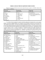
7. PROCESS EQUIPMENT DESIGN
Amount of water infeed = 212.5 kg/hrDry solid infeed = 10417 kg/hr Water content in product = 105.25 kg/hr Hence water dried in drier = 107.25 kg/hr Inlet air temperature = 150º C Outlet air temperature = 85º C Inlet temperature of feed = 30º C Discharge temperature = 80º C
Assuming wet bulb temperature of 80º C, 70% humidity of air.
The temperature of the air leaving the drier should be selected on the basis of an economic balance between drier cost and fuel cost. It has been that rotary driers are most economically operated when the total number of transfer units (NTU) range from 1.5 to 2.0. Assuming
</div><span class="text_page_counter">Trang 2</span><div class="page_container" data-page="2">The minimum velocity of air is set based on the particle size. Air flow rate of 100 lb/hr .ft<small>3 </small>is sufficient for 420 microns. Hence this will be used in application. The minimum velocity is used since it gives the smallest possible size of drier.
</div><span class="text_page_counter">Trang 3</span><div class="page_container" data-page="3">Amount of air required:
</div><span class="text_page_counter">Trang 4</span><div class="page_container" data-page="4">2. SHELL AND TUBE HEAT EXCHANGER
Where Q<small>H </small>= heat load of hot fluid Q<small>c </small> = heat load of cold fluid.
</div><span class="text_page_counter">Trang 5</span><div class="page_container" data-page="5">Cold fluid : (Water)
</div><span class="text_page_counter">Trang 6</span><div class="page_container" data-page="6">From perry 6<small>th.</small>cd. page 10.27
Considering 2-shell pass, 4 table pass i.e., 2.4 exchanger.
Corrected LMTD = 22.63 x 0.8 = 18.10° <small>lmtd </small>= 18.10<small>0</small>
3) Rounting of fluid:
Cleaner fluid is water --- Shell side. Unclean fluid is Aq.Ammonia .---Tube side
4) Heat Transfer Area:
Reference perry, page (10-44)U<small>d </small>for water in shell side, inorganic solvent in tube side is ranging between(100-250) BTU/ (F.Ft<small>2</small>.hr)
</div><span class="text_page_counter">Trang 7</span><div class="page_container" data-page="7">5) Fluid velocity check
a) Tube side: (aq ammonia)<small> </small>
</div><span class="text_page_counter">Trang 8</span><div class="page_container" data-page="8">S<small>m </small>= Gross sectional area at centre of shell Nb = No of baffles , L = length of tube p<small>1 </small> = 13 inches square pitch = 0.0206m
</div><span class="text_page_counter">Trang 13</span><div class="page_container" data-page="13">From figure 10.25 (a) page 10-31 friction factor f<small>k</small>
</div><span class="text_page_counter">Trang 14</span><div class="page_container" data-page="14">(ii) End zone pressure drop <small>c</small>
Area for flow though window Sw = Sw<small>g</small> – Sw <small>t</small> Sw<small>g </small>, from fig (10-18) , page (10-29), perry hand book.
Sw<small>g </small>= 0.029
</div><span class="text_page_counter">Trang 16</span><div class="page_container" data-page="16">8. MECHANICAL DESIGN OF PROCESS EQUIPMENTS
1. MECHANICAL DESIGN OF ROTARY DRIER
1. Flight design:
Number of flights = 3 x D. = 3 x2.09
=6.27 ≈ 7 flights are required using lip angle of 45°. Radial height is taken as 1/8 of diameter,
Radial height = 2.09/8 = 0.2615m.
2. Thickness of dryer:
Let x be the thickness of drier.
Mild steel can be used since it can withstand temperature up to 200°C.
</div><span class="text_page_counter">Trang 17</span><div class="page_container" data-page="17">The dryer is supported over two-tension roll assemblies, 20ft apart. It is uniformly distributed load.
Maximum bending moment = WL/8 = M.
</div><span class="text_page_counter">Trang 18</span><div class="page_container" data-page="18">3. Diameter of the feed pipe:
Feed rate =10417+212.9= 10629.9 kg/hour Density of feed = 1410 kg/m<small>3 </small>
Hence volumetric feed rate = 10629.9/1410 = 7.534 m<small>3</small> /hr Assuming the velocity of air = 150 m/hr , for chute inclination of 60<small>0</small>
Cross-section of feed chute = 7.53/ 150 = 0.050 m<small>2</small> Diameter of feed chute = √ (C.S.A. x4 /π) = √ (0.050 x 4 /π)
Humidity in air= 16743. 89 kg/ min = 915. 5 ft<small>3</small> /min Volume of this air , Q = 279.05 / 29 x 22. 4 x 303/ 298
= 219.9 m<small>3</small>/min = 718.9 ft<small>3 </small>/min
</div><span class="text_page_counter">Trang 19</span><div class="page_container" data-page="19">HP of blower = 0.000157 x Q x (head developed by water) = 0.000157 x718.9 x10
=1.2 hp 5. HP of exhaust fan
Outlet temperature of drier = 95.62 <small>0</small> C Humidity of outlet air = 0.65 x 0.00726
Total quantity of air going out = 16743.9 kg/hr = 279.05 kg/min Volume of this air = (279.05/29) x 22.4 x (368.62 /298)
= 406.9 m<small>3</small>/min or 1335.13 ft<small>3</small>/min. HP of exhaust fan = 0.000517 x 1335.13 x16
= 6.90 hp
6. Diameter of outlet and inlet pipe
At inlet conditions of 150 <small>0</small> C and humidity of 0.002 the volume of air handled = 219.2 x 423 / 303
=306 m<small>3</small>/min or 5.1 m<small>3</small>/sec.
Assuming air velocity = 25 m / s, C.S.A of inlet pipe = 5.1/25 =0.20 m<small>2 </small> Inlet pipe diameter = 0.504 m At outlet conditions of 95.62<small>0</small>C
The volume of air handled = 219.2 x 368 /313 = 4.43 m<small>3</small>/sec C.S.A of outlet pipe = 4.43 /25 = 0.178 m<small>2 </small> Outlet pipe diameter = 0.476 m
</div><span class="text_page_counter">Trang 20</span><div class="page_container" data-page="20">
2. MECHANICAL DESIGN OF HEAT EXCHANGER
(a) Shell side details Material : carbon steel Number of shell passes: 2 Working fluid: water Working pressure: 0.1N/mm<small>2</small> Design pressure : 0.11N/mm<small>2</small> Inlet temperature: 15<small>0</small>C Out let temperature: 35<small>0</small>C
Permissible stress for carbon steel: 95N/mm<small>2</small> Shell inner diameter: 438 mm
(b) Tube side details
</div><span class="text_page_counter">Trang 21</span><div class="page_container" data-page="21">Minimum thickness of shell must be=6.0 mm Including corrosion allowance shell thickness is 8mm
</div><span class="text_page_counter">Trang 22</span><div class="page_container" data-page="22">number of baffles,
N<small>b</small>+1=L/L =4.88/0.350=14 <small>S</small> N<small>b </small>=13
Thickness of baffles, t<small>b</small>=6mm
4.Tie Rods and spacers:
Tie rods are provided to retain all cross baffles and take support plates accurately. For shell diameter, 300-500mm
Diameter of Rod = 9mm Number of rods=4
5.Flanges
Design pressure=0.11 N/mm<small>2</small> Flange material IS:2004-1962,class 2 Bolting steel :5% Cr-Mo steel Gasket material: asbestos composition Shell inside diameter = 438mm. Shell thickness: 8mm=g<small>o</small> Outside diameter of shell: 446 mm
Allowable stress of flange material : 100MN/m<small>2</small> Allowable stress of bolting material = 138 MN/m<small>2</small> Shell thickness of flange = 10 mm.
Outside diameter of flange = 325 mm.
6. Determination of gasket width d /d = [(y-Pm)/(y-P(m+1))]<small>0.5</small>
</div><span class="text_page_counter">Trang 23</span><div class="page_container" data-page="23">Assume a gasket thickness of 10 mm
y = minimum design yield seating stress = 25.5 MN/m<small>2 </small>
m = gasket factor = 2.75
d<small>O</small>/d<small>i</small> = [(44.85-0.11 x2.75)/(44.85-0.11(2.75+1))]<small>0. 5</small> d<small>O </small>/d<small>i</small> = 1.001=1.001
d<small>O = </small> 1.001 x 0.438= 0.4385 m<small> </small> Minimum gasket width = (0.4385 -0.438)/2 = .00075. Taking gasket width of N= 0.010m
d<small>o</small>= 0.458 m.
Basic gasket seating width, b<small>o </small>= 5mm Diameter of location of gasket load reaction is
G= d<small>i </small>+ N =0.438+0.01 = 0.448 m
7.Estimation of Bolt loads. Load due to design pressure
</div><span class="text_page_counter">Trang 24</span><div class="page_container" data-page="24">Actual number of bolts =20
Radial clearance from bolt circle to point of connection of hub or nozzle and back of flange = R = 0.027 m
C =ID + 2(1.415g + R) =325 +2[1.41 x0.008+0.027] = 0.726m
Bolt circle diameter = 0.40163 m. Using bolt spacing Bs = 45mm
C = n Bs / 3.14 =44 x 0.045 / 3.14 = 0.63 Hence C = 0 .726
Calculation of flange outside diameter Let bolt diameter = 18 mm. A= C+ bolt diameter +0.02 =0.716 +0.018+0.02
</div><span class="text_page_counter">Trang 25</span><div class="page_container" data-page="25">= 0.764m.
Check for gasket width
A<small>b</small>S<small>G </small>/ (πGN) =1.54×10<small>-4</small> x44 x138/(3.14 x0.4486<small>2</small>) = 66.43 < 2 xy.
where S<small>G</small> is the Allowable stress for the gasket material
9.Flange moment computation:
(a) For operating condition
</div><span class="text_page_counter">Trang 26</span><div class="page_container" data-page="26">(b) For bolting condition
M<small>g</small>>M<small>o</small> ,Hence moment under operating condition M<small>g</small> is controlling, M<small>g</small>=M
10.Calculation of flange thickness
t<small>2</small> = M C<small>F</small> Y / (B S<small>F</small>), S<small>F</small> is the allowable stress for the flange material
Actual bolt spacing B<small>S</small> = πC/n = (3.14)(0.776)/(44) = 0.052m 11.Bolt Pitch Correction Factor
C<small>F</small> = [B<small>s</small> / (2d+t)]<small>0.5</small> = (0.052/(2 x0.018+0.11)<small>1/2</small> = 0.596
√C<small>F</small>=0.772
</div><span class="text_page_counter">Trang 27</span><div class="page_container" data-page="27">Actual flange thickness = √C<small>F</small> xt t<small>h</small>= 8mm including corrosion allowance
13.Tube sheet thickness Material: low carbon steel Total length of shell: 4.88 m Diameter of shell: 4.38 mm
Knuckle radius : 6% of crown radius =26.28 mm Total depth of head (H) = √(D<small>o</small>r<small>o</small>/2)
= √(438 x26.28/2) H = 75.86mm A= 0.5 R = 0.5 x 438/2 = 109.5 mm.
weight of vessel and contents = weight of ( shell + tube) weight of the steel = 7600 kg/m<small>3</small>.
</div><span class="text_page_counter">Trang 28</span><div class="page_container" data-page="28">17.Stresses in shell at the saddle
(a) At the topmost fibre of the cross section
f<small>1</small> =M /(k π R<small>112</small> t) k =k =1 <small>12</small> =598.06 / (3.14 x0..219 x0.01) <small>2</small>
= 35.22 kg/cm<small>2</small>
The stresses are well within the permissible values. Stress in the shell at mid point
f =M /(k π R<small>2</small> t) = 6014.4 / (1 x π 0.219<small>2</small> 0.01)
</div>