DESIGN AND ANALYSIS OF AIRCRAFT LANDING GEAR SYSTEM
Bạn đang xem bản rút gọn của tài liệu. Xem và tải ngay bản đầy đủ của tài liệu tại đây (964.28 KB, 25 trang )
<span class="text_page_counter">Trang 1</span><div class="page_container" data-page="1">
<b>International Journal of Advances in Engineering and Management (IJAEM) Volume 3, Issue 8 Aug 2021, pp: 374-398 www.ijaem.net ISSN: 2395-5252</b>
<b>Design and Analysis of Aircraft Landing Gear </b>
<i>Associate Professor, PESIT Bangalore South Campus, Bengaluru, Karnataka Corresponding Author: Suhas D </i>
--- Submitted: 01-08-2021 Revised: 07-08-2021 Accepted: 10-08-2021
<b>--- </b>
<b>ABSTRACT: </b> During ground and take-off procedures, the landing gear is the most critical component of an aircraft system. We can now see that the majority of aircraft structure failures occur primarily due to the failure of the landing gear system.
The landing gear normally holds extreme loads like side, compressive and drag. In contrast to the compressive load, the drag load and side load values are small. It is, thus, treated as a single dimensional structure. It is designed to take in the energy of the landing effect during landing in order to minimize the load transferred to the aircraft frame.
The general option for heavy aircraft is the oleo pneumatic landing gear strut. Aside from static strength, a very critical architecture criterion is energy absorption.
We then take an aircraft's conventional landing gear and it is designed using CATIA and evaluated using ANSYS software for structural protection. The assembly of landing gears is analysed using ANSYS tools for various composite materials and metal alloys.
By importing the model landing gear into the ANSYS program, Estimation of air craft landing gear linear stresses and deformation and analysis on main landing gear as well the nose landing gear of an air craft by linear static structural analysis. The results of the materials listed are compared and
the material with the highest factor of safety and least value of the extreme stress generated will be regarded as the best material to prevent structural failures of the model landing gear system.
<b>Keywords:Factor of Safety, Landing gear, Static </b>
<b>analysis, Stress, Total Deformation. </b>
<b>I. INTRODUCTION </b>
<b>1.1 Introduction to Landing GearSystem </b>This system is one of the pivotal subsystems of the airplane and is mostly built along with the aircraft structure because of its significant influence on the airplane's structural nature. The function of the landing gear of the airline is to provide during taxi, take-off, and landing operations, a suspension mechanism. The kinetic energy of the landing impact is consumed and dispelled, thus reducing the impact loads transmitted to theairframe.
<b>An aircraft has two landing gears: the Nose </b>
<b>Landing Gear and the Main Landing Gear. Not </b>
only is the nose wheel necessary for a safe landing, but it is also required for aircraft steering while taxiing on the ground. The main landing gear is aimed at allowing the aircraft to land safely. Both of these landing gears work to make jerk-freelandings. Airplane undercarriage bears the entire weight of an aircraft throughout taxiing and landing operations.These gear systems are connected to theaircraft's key structural components.
</div><span class="text_page_counter">Trang 2</span><div class="page_container" data-page="2">We can subdivide landing gear as:
1)
<b>Wheels to allow the operation on airport </b>runways, to and from them, and other hardsurfaces.
2)
<b>Skids werefound on Choppers, hot air </b>balloons, and some tail dragger aircraft in the tailarea.
Shock-absorbing equipment, fairings, controls, retraction mechanisms, cowling, warning systems, brakes, and structural members required to mount the gear to the aircraft are considered to be part of the undercarriage, regardless of the type used.
To authenticate structural robustness and structural design loads, it is necessary to compute the loads acting on the landing gears in-flight tests. The terrain load calibration test usually entails separating the landing gears from the test aircraft, then mounting it on a specifically designed test rig and applying required loads on the landing wheel system. Thus, it is not possible to fully simulate the stiffness of the relation between the landing wheel and the rig as the real stiffness of the connection with the aircraft. This will influence the efficiency of load calculationdata.
Horack suggested studying thelayout ofthelanding gear. Landing gear fatiguetest technology, load association of repeated loading, and state of service load. The application of lightweight materials was suggested byYangchen.
Generally, the following are the parameters of the landing wheel system to be ascertained:
</div><span class="text_page_counter">Trang 3</span><div class="page_container" data-page="3"><b>International Journal of Advances in Engineering and Management (IJAEM) Volume 3, Issue 8 Aug 2021, pp: 374-398 www.ijaem.net ISSN: 2395-5252</b>
<small>CG </small>
Height
Wheel track
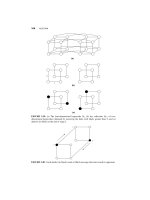
<b>Fig 2: Primary Parameters of System of Landing Gear </b>
The primary parameters of the landing gear are shown in Figure 1.2. The following are the definitions of the key parameters. The difference between extreme points of the landing wheel (i.e. the lowest point of the tire) to the spot of attachment to the airplane is the height of the landing gear. Seeing that landing wheels can be attached to the frame (body) or the wing, discrete meanings are given to the term height. The undercarriage heightis alsoa feature of the shock absorber and the deflection of the landing gears. Height isnormallydetermined while the airplane is grounded, during which it is under full load condition i.e. maximum weight for take-off; and the lowest height of the undercarriage i.e. maximum deflection condition.
We can see from the side view of Figure 2 the wheel base which is the distance betwixt the main wheel centreline and the nose wheel centre. Two segments of the landing gear are:
1.
Mainwheel,The main wheel is the primary gear that is nearer to the centerof mass of the airplane. The main wheel contacts the terrain first during the descent phase of the aircraft. In addition, the main gear leaves the deck at the terminal stage of the take-off process. On the other side, the main gear bears a significant part of the load of the aircraft on the ground. The front viewshowing the distance betwixt the left main wheel and the right main wheel is known as the wheel track. It will have more than one wheel if a gear is supposed to hold a large load. The weight of the landing gear is usually around three percent to five percent of the weight required forthe airplane to become airborne. The assembly of landing wheels, for instance, weighsaround7.25 tons in the case of a 747
</div><span class="text_page_counter">Trang 4</span><div class="page_container" data-page="4">landing gear. The selection process and the configurations of the landing gear are reviewed in thissegment.
Decision on whether the landing wheels are to be retractable, separable, or fixed is studied.
The geometry of the landing wheels, includingwheel height, wheelbase, and wheel track. Much essential design criteriathat affect the determination of the parameters of the landing wheels (e.g. Clearance of airplane from the terrain and rotation clearancerequirements for take-off) are studied in thissegment.
Landing gear and airplane centerof mass; and three design criteria(tip forward, tip back angles, and rotation requirements for take-off) areadded.
Subdivisions/specificationswhich are of mechanicalinnature of landingwheelssuch as tire size, shock absorber, strut size, guide,and retraction subdivisions are put forward.
The steps and procedure of the landing gearLanding wheels are the last major aircraft part constructed in terms of the construction procedure. In other words, prior to designing the landinggear, allprimeconstituents(such as the wing, tail, fuselage, and propulsion system) must bedeveloped. In addition,for landing wheels configuration, the aircraft with the aptest centerof mass and the most forward point of balance must be known. In some cases, the design of the undercarriage may cause the airplane designer to adjust the blueprint of theairplaneto meet the specifications of the outline of the landing wheelsystem.
The vital operations of landing wheels are as follows:
1.
To provide solidity to the airplane on the groundandduring unloading,loading,and taxiing.2.
Allow for free movement and steering of an airplane whiletaxiing.3.
A safe interspace is provided between different parts of the airplane when the aircraft is on the terrain to avoid any disfigurement caused by coming in contact with theground.4.
To cushion the shocks of the landing during the descentphase.5.
To enable smooth ascending by permitting theandrotation.
<b>II. LITERATURE SURVEY </b>
The following section of the report addresses some of the research workscarried out by various researchers concerningLanding Gear Systems, which aided us in getting the required information to carry out our project.
<b>DesignandAnalysisofaDualShockAbsorberLandingGearforCommercialAirplane [1]: </b>
<b>Sk Sariful Islam’s landing gear function is the </b>
most significant structural unit of an all-type aircraft that carries out the entire body safely on the ground during takeoff and landing. Depending on the configuration and size of the aircraft, several types of landing gear are used. With one front or nose landing gear unit and two primary landing gear systems, tri-cycle configurations are commonly used. Absorbing or dissipating energy is the primary feature of all types of shock absorbers. It reduces the impact of flying over the ground for a commercial aircraft, contributing to improved ride quality and increased comfortdue toreduceddisturbanceamplitude. The most significant bouncing mechanism in the landinggearisrepeated over and over, each time with a little less, until the up-and-down movement stops entirely. A single and dual shock absorber landing gear is modeled in this paper and a 3D model is obtained using CATIA v5, and ANSYS v12 is analyzed. Two types of shock observers(signal and dual) are compared to verify the best shockabsorber.
<b>Design and Analysis Aircraft Nose and Nose Landing Gear [2]: </b>
<b>Rajesh A, Abhay B T work on Tri-cycle </b>
arrangement landing gear is commonly used as it is simple; both structurally as well as aerodynamically convenient. It has its drawbacks, but it is preferable over other configurations. Factors such as its weight drag, sudden load application, acoustics, fatigue,etc. appear to slow down its life and efficiency. Among main landing gear and nose landing gear; the former carries about 85% of the total weight of aircraft and the latter carries around 12-15% of the weight. In contrast to the main landing gear, the nose landing gear is also a source of noise and its influence is prominent. The executive jet aircraft are extensively investigated in this project and a nose landing gear similar to those of executive jets is modeled using CATIA. The same geometry is imported into ANSYS ICEM and different angles of attack are evaluated for bodyflow.
Pressure variation, temperature, density,and velocity distribution are noted across the body and
</div><span class="text_page_counter">Trang 5</span><div class="page_container" data-page="5"><b>International Journal of Advances in Engineering and Management (IJAEM) Volume 3, Issue 8 Aug 2021, pp: 374-398 www.ijaem.net ISSN: 2395-5252</b>
obtained against the angle of attack. Checking the strength and stiffness of the built landing gear is alsoimportant.
Therefore, the static structural and impact test for built geometry has been carried out using ANSYS APDL and Explicit. For two different materials, such as steel and aluminum alloy, stress distribution and deformation were noted and primary acoustic results were comparedwith the availabledata.
<b>LANDING GEAR OF AN AIRCRAFT [3]: Durga Kumari and Love Sharma work </b>
on Landing gear in an aircraft's undercarriage. An airplane's landing gear is equipment that performs two primary purposes. First, it helps aircraft to land safely and successfully, and second, it supports aircraft in a restful state. The landing gear is constructed according to the aircraft's specifications and the essence of its function. An airplane's landing gear is equipment that performs two primary purposes. First, it helps aircraft to land safely and successfully, and second, it supports aircraft in a restful state. The landing gear is constructed according to the aircraft's specifications and the essence of its function. In this project, we will first study all the functional specifications and landing gear components that can affect an aircraft's purpose. It has been evident from the above work that the landing gear can be designed and modeled according to requirementsusing PRO-E. On a Pro/E assembly, we can perform integrated simulation and it is possible to generate an automatically meshed model containing very small sections. From the above analysis, early insight into its performance can be obtained and a concept model can be analyzed to obtain accurate stresses and displacements automatically. On this basis, by adjusting relevant parameters and materials, one can optimize the design. In this way, for a higherperformance, one can design a landing gear to suit the purpose. There have been several challenges forlandinggear designersand practitioners with the need to design landing gearwithminimalweight, minimum volume, high performance, improved life,and reduced life cyclecosts. Inconfiguration design, use of materials, design and research processes, and the potential design of landing gear for aircraft faces several newchallenges.
<b>Design and Structural Analysis of Main Landing Gear for Lockheed T-33 Jet Trainer Aircraft [4]: </b>
<b>Monisha M and Pooja S work focuses </b>
primarily on the structural design and study of a jet trainer aircraft's main landing gear, which is
but is still simple in design. An effort is made to synthesize graphically and comprehend the mechanism'skinematics.
ADAMS is used to check the design's mobility. In Unigraphics NX 10, computer 3D modeling of the assembly is carried out and finite element analysis is performed to analyze stresses produced at the rate of descent during landing. The linear static analysis is done with the aid of the ANSYS Workbench finite element software to measure the deflections of the main landing gear and to estimate the internal stresses. In this study, the simulation findings are discussed.
A subsonic American jet trainer aircraft has been designed to reflect the primary geometry of the main Lockheed T-33 Shooting Star (or T-Bird) landing gear. ADAMS software serves the task ofrecognizing
themechanism'sbasicskeleton,whichnevertheless embodies the dimensions of the model and defines the motion direction in real-time. The deflected structure of the landing gear in its maximally loaded state was shown by ANSYS Workbench, the finite element software. The graphical pictorialoutputs displayed varying stress levels corresponding to the gear geometry. Here, it is evident that 118.66 MPa is the maximum stress level, which is less than the permissible yield power. It can beinterpretedfrom thedesign stress measurement that the acceptable stress is 197.5 MPa and the design stress is 131.6 MPa, and the maximum stress from the numerical computation in the workbench is 118.66 MPa, so we can infer that the structure is secure and meets the landing criteria set by Lockheed T-33 aircraft.
<b>Design and Linear Static Analysis of Landing Gear [5]: </b>
<b>Muhammed Faizal Elayancheri work on Landing is </b>
one of the most common aircraft maneuvers. Because of its complex behavior, the landing gear is called a nonlinear structure. Significant amounts of impact forces are passed into the nose gear andmainlanding gear during the landing process. The main objective of this paper is to present an aircraft landing gear prototype using CATIA V5 software to research landing gear actions according to actual workingconditions.
Static loads are applied over the landing gear and internalforces are derived from key components of the landing gear, such as the separate study of the torque arm for the internal forces collected from the generalized modal, modeled with CATIA V5, and imported to MSC Patran. As a solver, MSC Nastran is used. Linear static analysis was performed from the obtained limit stresses to identify the stress of the
</div><span class="text_page_counter">Trang 6</span><div class="page_container" data-page="6"><b>DESIGN AND ANALYSIS OF AIRCRAFT LANDING GEAR USING DIFFERENT ALLOYS [6]: </b>
<b>Dr. V. Jaya Prasad, P. Sandeep Kumar Reddy, B. Rajesh, and T. Sridhar </b>
The purpose of this study was to examine the structural analysis of landing gear for various materials. The research explores the most appropriatematerial for the construction of the landing gear by analyzing the stress and deformation produced due to loadingconditions.
Analysis of stress plays an important role in finding structural protection and assembly integrity. The previous stress calculation helps to find suitable material and geometrical dimensions.
<b>Modal Analysis of a typical Landing Gear Oleo Strut [7]: </b>
<b>Dr. N Sreenivasa Babu </b>
Structural analysis to analyze the deformation and Von mises stress levels and analysis of vibration measuring frequency levels undervariousconditions.In comparison,fortake-off and landing conditions, various materials are examined and frequency levels at different loading conditions are compared. In the nodal analysis for various materials, the frequencies are evaluated. The frequency is 23.6339 Hz for the Ti 6Al-4V material oleo strut and the difference is not noticeable during take-off and landing. The results for displacement are 0.36 mm from the static study and Von mises Stress is 97.35 for Ferrium S53 material and is ideally suited and sustainable both for landing andtake-off.
<b>2.1 ResearchGap </b>
The complete load of the airplane has to be borne by the landing gear system and due to this,it has to be very powerful. This is why landing gear is made of steel because of its robust nature but it is not used in other parts of aircraft since it is heavy. Titanium alloys arealso used in the parts of a landinggear.
Our project aims at the explicit fundamental analysis of aircraft landing wheels for discrete alloys and compositematerials.
<b>2.2 Objective </b>
Following are the objectives of this project: Estimation of air craft landing gear linear stresses
and deformation by linear static structuralanalysis.
Perform static structural analysis on main landing gear as well the nose landing gear of an aircraft.
Design the air craft landing gear using different materials and alloys and analyze them and determine the best material to beused.
Evaluation of the Factor of Safety for the air craft landing equipment using different materials.
<b>2.3 PROBLEMDEFINITION </b>
Quite high loads impact the landing gear during landing. It is due to the weight of the aircraft and its rate of descent as well as forward speed during touchdown. If the load on the landing gear reaches the threshold value,the landing wheel will be damaged ordestroyed.
The landing wheel system should be adequately impervious to all presumed loads, however, the measurements taken should not be bulky, because it has to protect other airship structure parts from beingdamaged.
<b>III. METHODOLOGY </b>
<b>3.1 MethodologyOverview </b>The below flowchart shows the order of the steps to be followed to meet our project requirements.
</div><span class="text_page_counter">Trang 7</span><div class="page_container" data-page="7"><b>International Journal of Advances in Engineering and Management (IJAEM) Volume 3, Issue 8 Aug 2021, pp: 374-398 www.ijaem.net ISSN: 2395-5252</b>
<b>Fig 3: Methodology chart 3.2 DesignConsiderations </b>
Design is being done for solid landinggear. Medium-sized civil aircraft is being considered
for theproject.
Oleo pneumatic shock absorber is being used
because it has high effectiveness and it can absorb and release vertical kinetic energyconcurrently.
Sulfron, a para-aramid Twaron enhanced rubber is used as the material for the tires.
</div><span class="text_page_counter">Trang 8</span><div class="page_container" data-page="8"><b>3.3.2 Mechanical properties comparison between aluminum alloy, titaniumalloy, and Carbon Fiber </b>
Touch down the speed while landing is 160knots. A frictional and hydraulic force of shock
absorber is notconsidered.
Consider a perpendicular load applied to the designed landing gear for all the cases is 1400 KN or below.
Design is being done in such a way that it can withstand payload weight and structural weight
</div><span class="text_page_counter">Trang 9</span><div class="page_container" data-page="9"><b>International Journal of Advances in Engineering and Management (IJAEM) Volume 3, Issue 8 Aug 2021, pp: 374-398 www.ijaem.net ISSN: 2395-5252</b>
<b>Fig 5: Oleo piston of main landing gear </b>
<b>Fig 6: Disc unit of main landing gear </b>
<b>Fig 7: Upper link of main landing gear </b>
</div><span class="text_page_counter">Trang 10</span><div class="page_container" data-page="10"><b>Fig 8: Lower link of main landing gear </b>
<b>Fig 9: Wheels of main landing gear </b>
<b>4.1.2 NoseLandinggearcomponents </b>
<b>Fig 10: Lower support of nose landing gear </b>
</div><span class="text_page_counter">Trang 11</span><div class="page_container" data-page="11"><b>International Journal of Advances in Engineering and Management (IJAEM) Volume 3, Issue 8 Aug 2021, pp: 374-398 www.ijaem.net ISSN: 2395-5252</b>
<b>Fig 11: Link of nose landing gear </b>
<b>Fig 12: Strut of nose landing gear 4.2 Landing GearAssembly </b>
<b>Fig 13: Assembly of Main Landing Gear </b>
</div><span class="text_page_counter">Trang 12</span><div class="page_container" data-page="12"><b>Fig 14: Assembly of Nose Landing Gear </b>
<b>V. RESULTS AND ANALYSIS </b>
The core principle behind finite element analysis is to examine a structure, which is made up of several different items called components that are joined at a finite number of places known as nodes. These elements and nodes are then subjected to the loaded boundary conditions. Mesh is the term for a network of those elements. Meshing is the process of spatially dividing your geometry into elements and nodes. The stiffnessand mass distributionof the structure ismathematically represented using this mesh and material attributes. The default element size is determined by
severalcriteria, including the total size of the model, the proximity of other topologies, body curvature, and hence the feature's complexity. Structural analysis is done to analyze the deformation and Von misesstresses.
The problem is solved according to the problem definitions in the solution phase. The computer does all of the hard work of formulating and building matrices, and gives the deformations and stress values as the finaloutput
<b>5.1 Analysis of Main LandingGear 5.1.1 Aluminum7075 </b>
<b>Fig 15: Stress Distribution for Al 7075 </b>
</div>