Chỉnh xupap Động cơ volvo tad 851 pdf
Bạn đang xem bản rút gọn của tài liệu. Xem và tải ngay bản đầy đủ của tài liệu tại đây (6.59 MB, 8 trang )
21-4 Valve Mechanism
21-4 Valve Mechanism
hr ae Valves, Adjustment
sal i Or TT |J jh ®Bs
Tools:
88800014 Rotation tool
IMPORTANT!
Clean thoroughly before removal.
NOTICE! Normal valve clearance is set when the
engine is cold, or when it has been left to cool for at
least a half hour. Oil temperature < 80 °C (176 °F).
Removal
1 Remove the upper valve cover according to:
Upper valve cover, change, page 87.
2 Remove the plug at the flywheel.
Install 88800014 Rotation tool.
HOnức pe) FL
Bs/28F 7”
ron L
P0019449
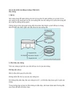
3 NOTICE! Crank counterclockwise, on the engine
flywheel side.
Crank the flywheel until the cylinder 1 mark aligns
with the mark on the flywheel housing.
The camshaft gear has two marks which
correspond to the mark on the flywheel.
P0019450 47705010 05-2017 © AB VOLVO PENTA
100
21-4 Valve Mechanism
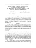
4 Check that the gearwheel's marking (1)
corresponds with the surface of the left side of the
cylinder head.
If not, crank the flywheel one more turn.
Marking (1) facing surface of the cylinder
head:
e The Inlet valves for cylinders (1), (3) and (5).
e The exhaust valves for cylinders (1), (2) and
(4).
“Né \V l // TPIT ED h ON A a
A3) (2Ÿ ING cH
Í Lh (LT
CF ề HỊ— Ô | A a
= Oo, @ ơơâ © © © e—-© ©
` —— Te eee a
TT
P0019452
A Inlet valve 1 Cylinder1 4 Cylinder4
B Exhaust valve 2 Cylinder2 5 Cylinder5
3. Cylinder 3 6 Cylinder 6
47705010 05-2017 © AB VOLVO PENTA 101
21-4 Valve Mechanism
OREM 3 AYD$ØRE®E°S92 Checks and adjustment, inlet valves
Sf. 3 Xi C C. .
Ơ CC VU 0 5 NOTICE! Cylinder (1) is on the opposite side in
No ĐÀN) OlF o iFiR)O Y= Se relation to the engine flywheel/gearwheel.
an (GPa bạc Check the valve clearance on the inlet valves for
lay" vate
cylinders (1), (3) and (5).
ee Ì
Check
(ae © et 6 Check the valve clearance for the inlet valves with
the aid of a feeler gauge set.
The clearance must be 0.4 +0.05 mm.
In the value is not correct, adjust the valve.
P0019454 Adjustment
P0019455 7 ~ Adjust inlet valve clearance between the rocker
102 arm and the valve yoke to 0.4 mm with the aid of
a feeler gauge set.
Loosen the adjuster screw locking nut on the
rocker arm. Turn the adjuster screw until the right
clearance is achieved.
Feeler gauges should be used when adjusting.
One 0.40 mm, the other 0.45 mm.
Set the clearance so that only the 0.40 mm feeler
gauge can be inserted without any great
resistance, and only slight resistance should be
felt when the feeler gauge is pulled back and
forth. It should not be possible to insert the 0.45
mm feeler gauge without resistance.
Counterhold the adjuster screw while tightening
the locking nut.
Tightening torque: 33 Nm (24.3 Ibf. ft.)
47705010 05-2017 © AB VOLVO PENTA
21-4 Valve Mechanism
2 OF a ) |: Checks and adjustment, exhaust valves
8 NOTICE! Cylinder (1) is on the opposite side in
relation to the engine flywheel/gearwheel.
Check the valve clearance on the exhaust valves
for cylinders (1), (2) and (4).
| fat EN †) Ne ite
ehoom
Check exhaust valves
9 Check the valve clearance for the mm.
with the aid of a feeler gauge set.
The clearance must be 0.5 +0.05
In the value is not correct, adjust the valve.
P0019458 Adjustment
10 Adjust exhaust valve clearance between the
rocker arm and the valve yoke to 0.5 mm with the
aid of a feeler gauge set.
Loosen the adjuster screw locking nut on the
rocker arm.
Turn the adjuster screw until the right clearance
is achieved.
Feeler gauges should be used when adjusting.
One 0.50 mm, the other 0.55 mm.
Set the clearance so that only the 0.50 mm feeler
gauge can be inserted without any great
resistance, and only slight resistance should be
felt when the feeler gauge is pulled back and
forth. It should not be possible to insert the 0.55
mm feeler gauge without resistance.
Counterhold the adjuster screw while tightening
the locking nut.
Tightening torque: 33 Nm (24.3 Ibf. ft.)
47705010 05-2017 © AB VOLVO PENTA 103
21-4 Valve Mechanism 11 Engines equipped with exhaust brake
885812 systems (VCB)
Adjustment of exhaust brake:
P0019459 Use 885812 Timing tool.
Adjust the piston on the exhaust brakes for
104
cylinders (1), (2) and (4).
Loosen the locking nut and adjust the screw until
zero clearance is retained.
Loosen the adjuster screw, (403°).
Counterhold the adjuster screw while tightening
the locking nut.
Tightening torque: 15 Nm (11.1 Ibf. ft.)
12 NOTICE! Crank counterclockwise, on the engine
flywheel side.
Crank the flywheel one turn until the cylinder 1
mark aligns with the mark on the flywheel
housing.
13 Check that the gearwheel marking corresponds
with the surface of the left side of the cylinder
head.
If not, crank the flywheel one more turn.
Marking left facing surface of the cylinder
head.
e The Inlet valves for cylinders (2), (4) and (6).
e The exhaust valves for cylinders (3), (5) and
(6).
47705010 05-2017 © AB VOLVO PENTA
21-4 Valve Mechanism
Checks and adjustment, inlet valves
14 NOTICE! Cylinder (1) is on the opposite side in
relation to the engine flywheel/gearwheel.
Check the valve clearance on the inlet valves for
cylinders (2), (4) and (6).
Check
15 Check the valve clearance for the inlet valves with
the aid of a feeler gauge set.
The clearance must be 0.4 +0.05 mm.
In the value is not correct, adjust the valve.
P0019462 Adjustment
16 Adjust inlet valve clearance between the rocker
arm and the valve yoke to 0.4 mm with the aid of
a feeler gauge set.
Loosen the adjuster screw locking nut on the
rocker arm. Turn the adjuster screw until the right
clearance is achieved.
Feeler gauges should be used when adjusting.
One 0.40 mm, the other 0.45 mm.
Set the clearance so that only the 0.40 mm feeler
gauge can be inserted without any great
resistance, and only slight resistance should be
felt when the feeler gauge is pulled back and
forth. It should not be possible to insert the 0.45
mm feeler gauge without resistance.
Counterhold the adjuster screw while tightening
the locking nut.
Tightening torque: 33 Nm (24.3 Ibf. ft.)
47705010 05-2017 © AB VOLVO PENTA 105
21-4 Valve Mechanism
“an o@ ghYb iQee ` f 1Á THẢ Checks and adjustment, exhaust valves
ụ
(5) a OK) 17 NOTICE! Cylinder (1) is on the opposite side in
relation to the engine flywheel/gearwheel.
EISy a oP Check the valve clearance on the exhaust valves
YI| PNỈ KI3] BOBYi Or NOK 1—)
tO dÌÌ oan dÌÌ li for cylinders (3), (5) and (6).
\= =jo —^ Ne
Check exhaust valves
18 Check the valve clearance for the mm.
with the aid of a feeler gauge set.
The clearance must be 0.5 +0.05
In the value is not correct, adjust the valve.
P0019465 Adjustment
19 Adjust exhaust valve clearance between the
106
rocker arm and the valve yoke to 0.5 mm with the
aid of a feeler gauge set.
Loosen the adjuster screw locking nut on the
rocker arm.
Turn the adjuster screw until the right clearance
is achieved.
Feeler gauges should be used when adjusting.
One 0.50 mm, the other 0.55 mm.
Set the clearance so that only the 0.50 mm feeler
gauge can be inserted without any great
resistance, and only slight resistance should be
felt when the feeler gauge is pulled back and
forth. It should not be possible to insert the 0.55
mm feeler gauge without resistance.
Counterhold the adjuster screw while tightening
the locking nut.
Tightening torque: 33 Nm (24.3 Ibf. ft.)
47705010 05-2017 © AB VOLVO PENTA
P0022851 21-4 Valve Mechanism
4 20 Engines equipped with exhaust brake
systems (VCB)
P0019449 Adjustment of exhaust brake:
Use 885812 Timing tool.
Adjust the piston on the exhaust brakes for
cylinders (3), (5) and (6).
Loosen the locking nut and adjust the screw until
zero clearance is retained.
Loosen the adjuster screw, (403°).
Counterhold the adjuster screw while tightening
the locking nut.
Tightening torque: 15 Nm (11.1 Ibf. ft.)
21 Remove 88800014 Rotation tool from the gear
ring.
Install the plug.
22 Insert plug for the flywheel mark.
23 Install the upper valve cover according to: Upper
valve cover, change, page 87.
P0019466
47705010 05-2017 © AB VOLVO PENTA 107