Das solution
Bạn đang xem bản rút gọn của tài liệu. Xem và tải ngay bản đầy đủ của tài liệu tại đây (2.05 MB, 26 trang )
<span class="text_page_counter">Trang 1</span><div class="page_container" data-page="1">
<small>vertraulich / confidential</small>
Overview of DAS Solutions
<small>15-Jul-2017</small>
</div><span class="text_page_counter">Trang 2</span><div class="page_container" data-page="2">▪ In-Building Design Trends
▪ Marketplace Solutions and Building Types▪ Approaches to In Building System Design
</div><span class="text_page_counter">Trang 3</span><div class="page_container" data-page="3"><small>vertraulich / confidential</small>
In-Building Design Trends
▪ Network Operators Prefer Passive Solutions
▪ Radiating cable now widely used
▪ Fibre optic technology used only where necessary<small>▪Solution for large buildings</small>
<small>3</small>
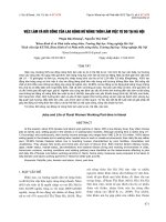
</div><span class="text_page_counter">Trang 4</span><div class="page_container" data-page="4">Passive and Active DAS
<b><small>Passive Solutions</small></b>
<b><small>Active Solutions</small></b>
<b><small>MainHub</small></b>
</div><span class="text_page_counter">Trang 5</span><div class="page_container" data-page="5"><small>vertraulich / confidential</small>
Why Use Distributed Antenna?
▪ Applicable where narrow range of frequencies are required and future expansion into other bands is not anticipated.
▪ Single or Dual band systems.
▪ To provide hot spot coverage of open areas.▪ Highly cost effective.
</div><span class="text_page_counter">Trang 6</span><div class="page_container" data-page="6">Why Use Radiating Cable?
▪ Flexibility / Cost- Effective Upgrading. ▪ Broadband capability
<small>2700MHz. </small>
▪ Advantages of leaky cable
<small>▪Less close / far signal difference.</small>
▪ Disadvantages of leaky cable
<small>▪Difficult to match with interior design.</small>
</div><span class="text_page_counter">Trang 7</span><div class="page_container" data-page="7"><small>vertraulich / confidential</small>
Radiating Cable vs Antenna
▪ Major issue is the topology of the required coverage area.
<small>rectangular or circular disposition.</small>
<small>and narrow office spaces such as those wrapping around the core of a high rise building.</small>
▪ A radiating cable solution is generally more costly (material wise) than an antenna solution.
▪ Flexibility / Cost
<small>unlimited number of services ranging from 1MHz to 2500MHz.</small>
<small>later without further installation costs.</small>
would require a new antenna system.
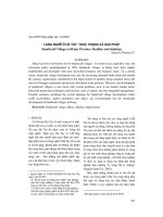
</div><span class="text_page_counter">Trang 8</span><div class="page_container" data-page="8">Antennas vs Radiating Cable
<small>Radiating CableCoverage</small>
<b><small>Signal Strength</small></b>
<b><small>Distance</small></b>
</div><span class="text_page_counter">Trang 9</span><div class="page_container" data-page="9">▪ High system reliability
Active System
▪ Active systems overcome insertion loss, restoring antenna EIRPs and uplink system noise figure
▪ Duplex cellphone systems require elaborate and relatively expensive linear BDAs
▪ Linearity is critical; multiple carriers escalate 3OIP and power rating of downlink PAs
▪ Multiple radio platforms necessitate band-dedicated BDAs
</div><span class="text_page_counter">Trang 10</span><div class="page_container" data-page="10">Passive DAS for LTE-A?
<b>Pros of Passive DAS</b>
▪ An all-passive coaxial cable system is highly linear
▪ Capable of handling multiple downlink carriers with no measurable IM products
▪ High system reliability.
<b>Cons of Passive DAS</b>
▪ Feeder cable size is typically limited to 7/8” or 1-5/8”▪ Not suitable for buildings that require long feeder runs▪ At high frequencies, the system loss becomes very high
▪ Lower DL coverage, poorer uplink sensitivity and reduced SNIR
</div><span class="text_page_counter">Trang 11</span><div class="page_container" data-page="11"><small>vertraulich / confidential</small>
Hybrid DAS
▪ Most cost effective solution
▪ Difficult to manage uplink active systemfrom interfering with passive DAS
<b><small>Hybrid Solutions</small></b>
<b><small>Master Unit</small></b>
<small>Coaxial Cable toAntennas</small>
<small>Coaxial Cable</small>
<b><small>RemoteUnitRF Repeater</small></b>
<small>Radiating CablesRadiating Cables</small>
<small>Coaxial Cable to Antennas</small>
<small>Coaxial Cable to Antennas</small>
<b><small>Donor BTS</small></b>
<small>11</small>
</div><span class="text_page_counter">Trang 12</span><div class="page_container" data-page="12">Hybrid DAS Application Scenarios
<b><small>1. Multi StorySkyscraper</small></b>
<b><small>Rad Cable</small></b>
<b><small>3. Campus Environment</small></b>
<b><small>Fiber OpticsRemote Unit</small></b>
<b><small>Fiber OpticsRemote Unit</small></b>
<b><small>Fiber OpticsMaster Unit</small></b>
<b><small>2. ShoppingCenter</small></b>
<b><small>Attached High Rise BuildingFiber</small></b>
<b><small>Master UnitFiber Optics</small></b>
</div><span class="text_page_counter">Trang 13</span><div class="page_container" data-page="13"><small>vertraulich / confidential</small>
Optimum Amplifier Placement
▪ Best results when amplifier is placed near to antenna.
<small>▪UL NF is minimized, i.e. better sensitivity</small>
▪ Trade-off between how close amplifier is placed to the antenna, and number of amplifiers needed.
<small>21</small>
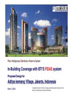
</div><span class="text_page_counter">Trang 14</span><div class="page_container" data-page="14">Optimum Amplifier Placement
▪ Scenario 1: No Amplifier
<small>BTS NF plus cable loss</small>
▪ Scenario 2: Amplifier Near the Antenna
<small>between BTS and amplifier.</small>
<b><small>System Noise Figure = 50 dB</small></b>
<b><small>System Noise Figure = 16.2 dB</small></b>
<b><small>RXNF = 10dB</small></b>
<b><small>Overall NF16.19dB</small></b>
</div><span class="text_page_counter">Trang 15</span><div class="page_container" data-page="15"><small>vertraulich / confidential</small>
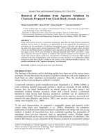
Optimum Amplifier Placement
▪ Scenario 3: Amplifier Far from Antenna
▪ Amplifier gain compensates for feeder loss and thereby increasing performance.
<b><small>System Noise Figure = 50 dB</small></b>
<b><small>RXNF = 10dB</small></b>
<b><small>Stage 1 Stage 2 Stage 3 Stage 4</small></b>
<b><small>Overall Gain-5dBOverall NF50dB</small></b>
<small>23</small>
</div><span class="text_page_counter">Trang 16</span><div class="page_container" data-page="16"><i><b><small>NF</small><sub>h</sub></b></i>
</div><span class="text_page_counter">Trang 17</span><div class="page_container" data-page="17"><small>vertraulich / confidential</small>
<b>Approaches to ImplementCoverage Solutions</b>
</div><span class="text_page_counter">Trang 18</span><div class="page_container" data-page="18">Coverage Solutions
<b><small>RF Repeater, Pico Repeater + DAS</small></b>
<small>E.g., Small Restaurant and Building</small>
<b><small>RF Repeater, Booster + DAS</small></b>
<small>E.g., Supermarket, Residential Building</small>
<b><small>BTS + DAS</small></b>
<small>E.g., Office Building, Shopping Mall</small>
<b><small>BTS + Fiber Repeater / Booster + DAS</small></b>
<small>E.g., Airport, Megamall</small>
</div><span class="text_page_counter">Trang 19</span><div class="page_container" data-page="19"><small>vertraulich / confidential</small>
High Capacity + Small Coverage Applications
<b><small>WCDMA BTSDCS BTSGSM_B BTS</small></b>
<b><small>GSM_A BTS</small></b>
<b><small>Basement Car ParkTPX</small></b>
<small>27</small>
</div><span class="text_page_counter">Trang 20</span><div class="page_container" data-page="20">High Capacity + Large Coverage Applications
▪ Fiber optic repeaters are often used for large scale in-buildings where high coverage and capacity are needed.
▪ Typical applications are in airports, underground metros, exhibition halls, campus buildings, etc.
</div><span class="text_page_counter">Trang 21</span><div class="page_container" data-page="21"><b><small>Donor Antenna</small></b>
</div><span class="text_page_counter">Trang 22</span><div class="page_container" data-page="22">Low Capacity + Large Coverage Applications
Optical Repeaters
<b><small>ANTOptical Fiber</small></b>
</div><span class="text_page_counter">Trang 23</span><div class="page_container" data-page="23"><small>vertraulich / confidential</small>
Low Capacity + Small Coverage Applications
<b><small>Small OfficeDonor </small></b>
▪ Using Indoor Pico Repeater
<small>31</small>
</div><span class="text_page_counter">Trang 24</span><div class="page_container" data-page="24"><b>Summary</b>
</div><span class="text_page_counter">Trang 25</span><div class="page_container" data-page="25"><small>vertraulich / confidential</small>
▪ The new Rosenberger Smart DAS solution can provide a flexible solution for a high power hybrid DAS and low power active DAS.
<small>33</small>
</div><span class="text_page_counter">Trang 26</span><div class="page_container" data-page="26"><b>THANK YOU</b>
<b>www.rosenbergerap.com</b>
</div>