polar code decoder hardware design for 5g implemented on fpga
Bạn đang xem bản rút gọn của tài liệu. Xem và tải ngay bản đầy đủ của tài liệu tại đây (3.1 MB, 67 trang )
<span class="text_page_counter">Trang 1</span><div class="page_container" data-page="1">
<b>HO CHI MINH CITY UNIVERSITY OF TECHNOLOGY </b>
</div><span class="text_page_counter">Trang 2</span><div class="page_container" data-page="2">THIS THESIS IS COMPLETED AT
HO CHI MINH CITY UNIVERSITY OF TECHNOLOGY – VNU-HCM Supervisor: Doctor Trần Hoàng Linh
Examiner 1: Doctor Bùi Trọng Tú
Examiner 2: Doctor Nguyễn Minh Sơn
This master’s thesis is defended at HCM City University of Technology, VNU- HCM City on January 12<sup>th</sup> 2024
Master’s Thesis Committee:
1. Associate Professors – Doctor Trương Quang Vinh : Chairman 2. Associate Professors – Doctor Hoàng Trang : Commissioner 3. Doctor – Nguyễn Lý Thiên Trường : Secretary 4. Doctor – Bùi Trọng Tú : Reviewer 1 5. Doctor – Nguyễn Minh Sơn : Reviewer 2
Approval of the Chair of Master’s Thesis Committee and Dean of Faculty of Electrical and Electronics Engineering after the thesis being corrected (If any).
<b><small>CHAIR OF THESIS COMMITTEE DEAN OF FACULTY OF ELECTRICAL AND ELECTRONICS ENGINEERING </small></b>
</div><span class="text_page_counter">Trang 3</span><div class="page_container" data-page="3"><small>VIETNAM NATIONAL UNIVERSITY - HO CHI MINH CITY </small>
<b><small>HO CHI MINH CITY UNIVERSITY OF TECHNOLOGY</small></b>
<b> <small>SOCIALIST REPUBLIC OF VIETNAM Independence – Freedom - Happiness</small></b>
<b> </b>
<b>THE TASK SHEET OF MASTER’S THESIS</b>
Full name: Nguyễn Đức Nam Student ID: 2070356
Date of birth: 29-04-1996 Place of birth: Bà Rịa – Vũng Tàu Major: Electronics Engineering Major ID: 8520203
<b>I. THESIS TITLE (In Vietnamese): THIẾT KẾ PHẦN CỨNG GIẢI MÃ CỰC (POLAR CODE) CHO 5G THỰC HIỆN TRÊN FPGA/ASIC</b>
<b>II. THESIS TITLE (In English): POLAR CODE DECODER HARDWARE DESIGN FOR 5G IMPLEMENTED ON FPGA/ASIC</b>
<b>III. TASKS AND CONTENTS: </b>
<b>To design and implement a polar code SC decoder on an FPGA using Verilog, improve the throughputs of the Semi-parallel Successive Cancellation. </b>
<b>To reduce latency cycles by improving the architecture to decode the codeword in parallel based on the Semi-parallel Successive Cancellation. </b>
<b>To improve fmax by analyzing and reducing the most critical delay path of the Semi-parallel Successive Cancellation. </b>
<b>To evaluate the performance of the FPGA-based polar code implementation in terms of resource utilization, fmax, latency, throughput. </b>
<b>IV. THESIS START DAY: 4/9/2023</b>
<b>V. THESIS COMPLETION DAY: 18/12/2023</b>
<b>VI. SUPERVISOR: DOCTOR TRẦN HOÀNG LINH </b>
<i>Ho Chi Minh City, date 18/12/2023 </i>
<b>SUPERVISOR </b>
(Full name and signature)
<b>HEAD OF DEPARTMENT </b>
(Full name and signature)
<b>DEAN OF FACULTY OF ELECTRICAL AND ELECTRONICS ENGINEERING </b>
(Full name and signature)
</div><span class="text_page_counter">Trang 4</span><div class="page_container" data-page="4"><b>ACKNOWLEDGEMENTS </b>
<i>During my time studying and training at Ho Chi Minh City University of Technology, I received enthusiastic guidance and teaching from teachers, especially teachers working at the Department of Electrical and Electronics Engineering have imparted to me theoretical and practical knowledge over the past time. During the process of writing my thesis, I received encouragement, guidance and valuable help from teachers, family and friends. With the deepest respect and gratitude, I would like to send my sincere thanks to the teachers of Ho Chi Minh City University of Science and Technology, the teachers of the Department of Electrical and Electronics Engineering - those who are constantly enthusiastic and inspiring to gain valuable knowledge for us. </i>
<i>In particular, I would like to send my sincere thanks to my instructor - Dr. Tran Hoang Linh. Over the past time, thanks to your enthusiastic help and guidance, I have had valuable and useful experiences. Your comments, encouragement and </i>
<i>encouragement are the driving force for me to try my best to complete this thesis. Through this, I also send my sincere thanks to my family, friends and especially my parents - who always care, support and assist me in successfully completing this thesis. </i>
<i>With limited time and limited experience, the thesis will inevitably have shortcomings. I look forward to receiving comments and guidance from teachers so that I can improve, supplement knowledge, raise awareness and better serve practical work in the future. </i>
<i>I sincerely thank you. Best regards, </i>
<i>Ho Chi Minh City, date 18/12/2023 </i>
<b> Nguyễn Đức Nam </b>
</div><span class="text_page_counter">Trang 5</span><div class="page_container" data-page="5"><b>ABSTRACT </b>
This thesis demonstrate an effective field-programmable gate array (FPGA) implementation of successive-cancellation (SC) decoder for Polar code that is standard in 5G wireless system. We focus on improving the best contribution architecture Semi-parallel SC decoder. Based on that, we show that the SC decoder of length N can be further optimized by decoding the codeword in parallel to reduce N/2 latency cycles, and improve max clock frequency by refining architecture of the process elements. We demonstrate an FPGA implementation of the decoder architecture for a 1024-bit-
length polar code and show that our FPGA decoder can achieve more 50% throughput comparing to the Semi-parallel SC decoder without significantly increasing the
hardware resources.
<b>TÓM TẮT LUẬN VĂN THẠC SĨ</b>
Luận án này chứng minh việc triển khai mảng cổng lập trình trường (FPGA) một cách hiệu quả của bộ giải mã successive-cancellation (SC) cho mã Polar – mã tiêu chuẩn trong hệ thống không dây 5G. Chúng tôi tập trung vào việc cải thiện kiến trúc của thiết kế đóng góp tốt nhất Bộ giải mã SC bán song song (Semi-Parallel SC Decoder). Dựa trên đó, chúng tơi cho thấy bộ giải mã SC có độ dài N có thể được tối ưu hóa hơn nữa bằng cách giải mã các từ mã một cách song song để giảm chu kỳ độ trễ N/2 và cải thiện tần số tối đa bằng cách tinh chỉnh kiến trúc của các bộ tính tốn giải. Chúng tơi chứng minh việc triển khai FPGA của kiến trúc bộ giải mã cho mã cực có độ dài 1024 bit và cho thấy rằng bộ giải mã FPGA của chúng tơi có thể đạt được thông lượng cao hơn 50% so với bộ giải mã SC bán song song mà không làm tăng đáng kể tài nguyên phần cứng.
</div><span class="text_page_counter">Trang 6</span><div class="page_container" data-page="6"><b>THE COMMITMENT </b>
The author hereby declares that this is his own research work. The research results and conclusions in this thesis are truthful, and are not copied from any source or in any form. References to sources (if any) have been cited and reference sources recorded according to regulations.
Thesis author, Nguyễn Đức Nam
Ho Chi Minh University of Technology
<i>Ho Chi Minh City, date 18/12/2023</i>
</div><span class="text_page_counter">Trang 7</span><div class="page_container" data-page="7"><b>TABLE OF CONTENTS </b>
<small>1. INTRODUCTION ...1 </small>
<small>1.1 Overview ...1 </small>
<small>1.2 Related science researching ...2 </small>
<small>1.3 Tasks and expected results ...5 </small>
<small>2. PRELIMINARIES ...5 </small>
<small>2.1 Polar Code Construction and Encoding ...5 </small>
<small>2.2 Successive Cancellation (SC) Decoding ...7 </small>
<small>3.4 Partial Sum Registers ...24 </small>
<small>3.5 Partial Sum Update Logic ...25 </small>
<small>3.6 Frozen Channel ROM ...27 </small>
<small>3.7 Controller ...28 </small>
<small>4. IMPLEMENTATION RESULTS ...31 </small>
<small>4.1 Polar Code Encoder & Decoder on Matlab ...31 </small>
<small>4.2 Polar Code Decoder Simulation on Model Sim ...35 </small>
<small>4.3 Polar Code Decoder Function test on FPGA DE10 ...37 </small>
<small>4.4 Polar Code Decoder Synthesis Result on FPGA Stratix IV ...38 </small>
<small>5. CONCLUSION AND FUTURE IMPROVING WORK ...39 </small>
<small>6. REFERENCE ...40 </small>
<small>7. APPENDIX ...42 </small>
</div><span class="text_page_counter">Trang 8</span><div class="page_container" data-page="8"><b>LIST OF FIGURES </b>
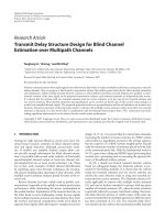
<small>Figure 1-1 Roadmap of channel coding in wireless communication systems. ...2 </small>
<small>Figure 2-1 Polar code encoder with N=8 ...6 </small>
<small>Figure 2-2 Butterfly-based SC decoder with N=8 ...8 </small>
<small>Figure 2-3 Scheduling for the butterfly-based SC decoder with N=8 ...9 </small>
<small>Figure 2-4 Scheduling and LR data flow graph of a semi-parallel SC decoder with N=8 and P=2 ... 11 </small>
<small>Figure 2-5 Utilization rate 𝛼𝑆𝑃 and relative-speed factor 𝜎𝑆𝑃 for the semiparallel SC decoder. ... 13 </small>
<small>Figure 2-6 Semi-parallel SC decoder architecture... 14 </small>
<small>Figure 2-7 Sign and magnitude processing element architecture. ... 17 </small>
<small>Figure 3-1 Enhanced semi-parallel SC decoder high-level architecture ... 18 </small>
<small>Figure 3-2 Schedule for original reference and enhanced semi-parallel SC decoder. ... 19 </small>
<small>Figure 3-3 RTL architecture of a standard PE ... 21 </small>
<small>Figure 3-4 Mirrored decoding graph for N=8 ... 22 </small>
<small>Figure 3-5 Organization of the LLR memory for N=8 and P=2 with uniform memory block size. ... 24 </small>
<small>Figure 3-6 Architecture of the partial sum registers with N=8 ... 25 </small>
<small>Figure 3-7 Frozen Channel ROM ... 28 </small>
<small>Figure 3-8 RTL design of the stage number ... 29 </small>
<small>Figure 3-9 RTL design of the portion 𝑝𝑠 of a stage ... 29 </small>
<small>Figure 3-10 RTL design of the LLR memory read/write address ... 30 </small>
<small>Figure 3-11 RTL design of the partial sum register read address ... 30 </small>
<small>Figure 3-12 RTL design of the F/G function selecting signal ... 30 </small>
<small>Figure 4-1 Polar code system with BPSK-AWGN channels ... 31 </small>
<small>Figure 4-2 MATLAB test bench data generating scripts ... 32 </small>
<small>Figure 4-3 Test bench data generated by MATLAB ... 32 </small>
<small>Figure 4-4 BPSK modulation over an AWGN channel ... 33 </small>
</div><span class="text_page_counter">Trang 9</span><div class="page_container" data-page="9"><small>Figure 4-5 ModelSim test bench scripts ... 35 </small>
<small>Figure 4-6 Memory loading and decoding process in ModelSim ... 35 </small>
<small>Figure 4-7 Model Sim simulation result ... 36 </small>
<small>Figure 4-8 Function test on FPGA DE10 ... 37 </small>
<small>Figure 4-9 Resource usage ... 38 </small>
<small>Figure 4-10 Max clock frequency result ... 38 </small>
<small>Figure 7-1 Flow Summary... 42 </small>
<small>Figure 7-2 Flow Non-Default Global Settings ... 42 </small>
<small>Figure 7-3 Flow Elapsed Time ... 43 </small>
<small>Figure 7-4 Analysis & Synthesis Summary ... 43 </small>
<small>Figure 7-5 Analysis & Synthesis Settings ... 44 </small>
<small>Figure 7-6 Analysis & Synthesis Source Files Read ... 44 </small>
<small>Figure 7-7 Analysis & Synthesis Resource Usage Summary ... 45 </small>
<small>Figure 7-8 Analysis & Synthesis Resource Utilization by Entity ... 45 </small>
<small>Figure 7-9 Analysis & Synthesis Post-Synthesis Netlist Statistics for Top Partition ... 46 </small>
<small>Figure 7-10 Fitter Summary ... 46 </small>
<small>Figure 7-11 Fitter Settings ... 47 </small>
<small>Figure 7-12 Fitter Resource Usage Summary ... 47 </small>
<small>Figure 7-13 Fitter Resource Utilization by Entity ... 48 </small>
<small>Figure 7-14 Timing Analyzer Summary ... 48 </small>
<small>Figure 7-15 Timing Analyzer SDC File List ... 49 </small>
<small>Figure 7-16 Timing Analyzer Clocks ... 49 </small>
<small>Figure 7-17 Timing Analyzer Fmax Summary at Slow 900mV 85C Model ... 50 </small>
<small>Figure 7-18 Timing Analyzer Fmax Summary at Slow 900mV 0C Model ... 50 </small>
<small>Figure 7-19 Timing Analyzer Multicorner Timing Analysis Summary ... 51 </small>
<small>Figure 7-20 MATLAB decoder results, same as original message (1-12 test cases) ... 52 </small>
<small>Figure 7-21 ModelSim decoder simulation and verification results (1-12 test cases) ... 53 </small>
</div><span class="text_page_counter">Trang 10</span><div class="page_container" data-page="10"><small>Figure 7-22 MATLAB decoder results, same as original message (13-24 test cases)... 54 Figure 7-23 ModelSim decoder simulation and verification results (13-24 test cases) ... 55 </small>
</div><span class="text_page_counter">Trang 11</span><div class="page_container" data-page="11"><b>LIST OF TABLES </b>
<small>Table 1-1 Comparison implementation for 1024-bit polar codes using SCD architectures on Stratix IV FPGA. ...4 Table 4-1 Simulation result, frame error rate of polar codes of length N = 1024 the SC </small>
<small>decoding of the 3GPP 5G standard under offset min-sum decoding. All simulations were performed using BPSK modulation over an AWGN channel... 34 Table 4-2 Comparison of our result for 1024-bit polar codes with other architectures on Stratix IV FPGA. ... 39 </small>
</div><span class="text_page_counter">Trang 12</span><div class="page_container" data-page="12"><b>1. INTRODUCTION </b>
<b>1.1 Overview </b>In 2008, Arıkan [1] introduced polar codes as a significant theoretical breakthrough aimed at achieving the capacity of symmetric channels. These codes are grounded in the concept of channel polarization, wherein the combination and division of channels lead to the transformation of a set of N identical binary-input discrete memoryless channels (B-DMC) into a group of polarized channels. Within this transformation, some channels become noiseless, approaching a capacity of one (termed as good channels), while others become noisy, with their capacity diminishing to zero (referred to as bad channels). This innovative approach enables the optimization of channel performance through strategic channel polarization techniques.
As the channel number, or code length, approaches infinity, the proportion of good channels to the total channels converges toward the capacity of the original channel. This phenomenon distinguishes polar codes from traditional channel codes like Turbo/LDPC codes. Polar codes introduce a novel concept in coding design, departing from the conventional approaches and showcasing a unique perspective on optimizing communication systems.
In practical applications, channel coding serves as a crucial technology for ensuring reliable transmission, particularly in wireless communications. Figure 1-1 illustrates the progression of channel code applications across 3G to 5G wireless systems. This roadmap highlights the pivotal role of channel coding in advancing the reliability and performance of wireless communication technologies over the years.
The 5G systems introduce more stringent requirements for transmission latency (1ms) and reliability (99.999%), posing challenges that traditional Turbo codes struggle to meet. In 2019, IEEE communication society published the best readings of polar coding online [2] show that polar codes provides excellent error-correcting performance with low decoding complexity for practical blocklengths when combined List SC
</div><span class="text_page_counter">Trang 13</span><div class="page_container" data-page="13">decoding with CRC check. These favorable traits have led to polar codes being used in the 5G wireless standard, which is a testament to their outstanding performance.
Figure 1-1 Roadmap of channel coding in wireless communication systems. For the decoding of polar codes, the concept of list successive cancellation decoding (LSCD) [3] [4] was introduced. LSCD involves generating L decoding paths by employing L parallel successive cancellation decodings (SCDs) [5] [6]. However, it's important to note that this method comes with increased implementation complexity and decoding latency. Enhancements in the implementation of the successive cancellation (SC) decoder play a crucial role in improving the overall implementation of LSCD. Consequently, our focus centers on optimizing the FPGA implementation of the Semi-parallel SC decoder [5], which forms the core of the original LSCD approach. Designing the high-throughput and low-latency architecture is the key issue of hardware implementation.
<b>1.2 Related science researching </b>
In the realm of hardware implementation, there is a pursuit of high-throughput and low-latency architectures for both Successive Cancellation (SC) and Successive Cancellation List (SCL) decoders in practical applications. Leroux et al. [7] introduced the pipelined-tree architecture to enhance the throughput of the SC decoder, while in [5], they proposed a semi-parallel architecture for a similar purpose. Building upon
</div><span class="text_page_counter">Trang 14</span><div class="page_container" data-page="14">these advancements, Zhang and Parhi [8] designed sequential and overlapped architectures to further reduce the decoding latency of the SC decoder. Additionally, Yuan and Parhi [9] introduced the concept of multi-bit decision to improve the throughput of the SC decoder. These efforts underscore the ongoing endeavors to optimize hardware implementations by exploring various architectural designs and decoding techniques, aiming to strike a balance between high throughput and low latency in decoding processes.
Several papers have delved into the FPGA implementation of polar decoders, each offering unique insights and methodologies [10] [5] [11] [12]. Pamuk [10] contributed by presenting an FPGA implementation of a belief propagation decoder tailored for polar codes. Leroux et al. [5] introduced a semi-parallel Successive Cancellation (SC) decoder architecture designed to maximize FPGA resource utilization efficiently. However, it's noteworthy that the latency associated with the semi-parallel decoder architecture, as presented by Leroux et al. [5], is constrained to at
<i>least 2 N – 2 cycles Consequently, its throughput is limited to approximately fmax/2N, where N denotes the length of the considered polar code, and fmax represents the </i>
maximum clock frequency. In another approach, Dizdar et al. [12] proposed an SC decoder architecture leveraging only combinational logic circuits. Their work demonstrated that latency could be minimized by combining combinational and synchronous SC decoders of shorter lengths. These diverse approaches highlight the ongoing efforts to enhance the FPGA implementation of polar decoders by addressing factors such as resource utilization, latency reduction, and overall decoding efficiency. Y. Ideguchi contributes to the field with a notable proposal for an efficient FPGA implementation of a Successive Cancellation (SC) decoder for polar codes [13]. In their work, they showcase the FPGA implementation of the decoder architecture tailored for a 1024-bit-length polar code. Remarkably, their FPGA decoder achieves a threefold increase in throughput compared to the conventional sequential semi-parallel decoder, all while managing to avoid a substantial increase in hardware resource utilization. The
</div><span class="text_page_counter">Trang 15</span><div class="page_container" data-page="15">emphasis on achieving higher throughput with optimized resource utilization is a significant stride in FPGA implementations of polar decoders.
As part of future work, the focus is directed towards further enhancing the frequency, highlighting an ongoing commitment to advancing the performance and efficiency of FPGA implementations in the realm of polar code decoding. This continuous pursuit of improvement reflects the dynamic nature of research in FPGA-based polar code decoders.
Table 1-1 Comparison implementation for 1024-bit polar codes using SCD architectures on Stratix IV FPGA.
Design N # of ALUTs
# of Register
RAM kbits
Fmax MHz
Latency cycles
TP Mbps 2013 Ref. [5] 1024 4130 1691 15 173 2084 85 2014 Ref. [6] 1024 4324 2046 808 223 - 73 2014 Ref. [6] 1024 4223 2069 808 212 - 104 2019 Ref. [13] 1024 8558 13056 0 97 312 318
</div><span class="text_page_counter">Trang 16</span><div class="page_container" data-page="16"><b>1.3 Tasks and expected results </b>
To design and implement a polar code SC decoder on an FPGA using Verilog, improve the throughputs of the Semi-parallel Successive Cancellation
To reduce latency cycles by improving the architecture to decode the codeword in parallel based on the Semi-parallel Successive Cancellation To improve fmax by analyzing and reducing the most critical delay path
of the Semi-parallel Successive Cancellation
To evaluate the performance of the FPGA-based polar code implementation in terms of resource utilization, fmax, latency, throughput By improving the Semi-parallel Successive Cancellation, our expectation results are:
Reduce N/2 the latency cycles, 512 clock cycles in case N=1024 Improve fmax from 173MHz to more than 200MHz
Improve throughput from 85 Mbps to more than 130 Mbps
<b>2. PRELIMINARIES </b>
<b>2.1 Polar Code Construction and Encoding </b>
Polar codes represent linear block codes with a length of N = 2<small>n</small>, where their generator matrix is formulated through the n<small>th</small> Kronecker power of the matrix 𝐹 = [<sup>1</sup> <sup>0</sup>
1 1]. For example, for n = 3,
𝐹<sup>⨂3</sup> =
[1 01 1<sup> </sup>
0 00 0<sup> </sup>1 0
1 1<sup> </sup>1 01 1<sup> </sup>1 0
1 1<sup> </sup>0 00 0<sup> </sup>1 0
1 1<sup> </sup>1 01 1<sup> </sup>
0 00 0<sup> </sup>
0 00 00 0
0 0<sup> </sup>0 00 01 0
1 1<sup> </sup>0 00 01 0
1 1<sup> </sup>1 01 1 <sup>]</sup>
(1)
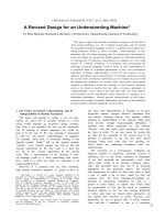
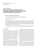
</div><span class="text_page_counter">Trang 17</span><div class="page_container" data-page="17">Figure 2-1 depicts the equivalent graph representation of 𝐹<small>⨂3</small>, where 𝑢 = 𝑢<sub>0</sub><small>7</small>represents the information-bit vector and 𝑥 = 𝑥<sub>0</sub><sup>7</sup> represents the codeword transmitted through the channel. The vector notation adheres to the conventions established in [1], namely 𝑢<sub>𝑎</sub><small>𝑏</small> consists of bits 𝑢<sub>𝑎</sub>, … , 𝑢<sub>𝑏</sub> of the vector u.
Figure 2-1 Polar code encoder with N=8
In the process of decoding received vectors with an SC decoder, each estimated bit 𝑢̂<sub>𝑖</sub> under the assumption of correct decoding for bits 𝑢<sub>0</sub><sup>𝑖−1</sup>, tends toward a predetermined error probability, approaching either 0 or 0.5. Additionally, as established in [1], the fraction of estimated bits with a low error probability converges toward the capacity of the underlying channel. Polar codes leverage this phenomenon, known as channel polarization, by utilizing the most reliable 𝐾 bits for information transmission while "freezing" or setting the remaining 𝑁 − 𝐾 bits to a predetermined value, often 0.
</div><span class="text_page_counter">Trang 18</span><div class="page_container" data-page="18"><b>2.2 Successive Cancellation (SC) Decoding </b>
When provided with a received vector corresponding to a transmitted codeword, the SC decoder sequentially estimates the transmitted bits, starting with 𝑢<sub>0</sub> to 𝑢<sub>𝑁−1</sub>. At step 𝑖, if 𝑖 is not in the frozen set, the SC decoder estimates 𝑢̂<sub>𝑖</sub> such that:
𝑢̂<sub>𝑖</sub> = {<sup>0, 𝑖𝑓 </sup>
<small>Pr(𝑦,𝑢̂</small><sub>0</sub><sup>𝑖−1</sup><small>|𝑢𝑖=0)Pr(𝑦,𝑢̂</small><sub>0</sub><sup>𝑖−1</sup><small>|𝑢</small><sub>𝑖</sub><small>=1)</small> > 11, 𝑜𝑡ℎ𝑒𝑟𝑤𝑖𝑠𝑒,
(2)
where Pr(𝑦, 𝑢̂<sub>0</sub><sup>𝑖−1</sup>|𝑢<sub>𝑖</sub> = 𝑏) represents the probability that y was received, given the previously decoded bits as 𝑢̂<sub>0</sub><sup>𝑖−1</sup>, with the currently decoded bit being 𝑏, where 𝑏 ∈ {0, 1}. In this context, the ratio of probabilities in the above function serves as the likelihood ratio (LR) of bit 𝑢̂<sub>𝑖</sub>.
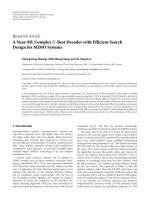
The SC decoding algorithm sequentially assesses the likelihood ratio LR 𝐿<sub>𝑖</sub> of each bit 𝑢̂<sub>𝑖</sub>. Arıkan demonstrated that these LR computations can be efficiently carried out in a recursive manner using a data flow graph resembling the structure of a fast Fourier transform. This structure, illustrated in Fig. 2, is referred to as a butterfly-based decoder. The messages exchanged within the decoder are LR values denoted as 𝐿<sub>𝑙,𝑖</sub>, where 𝑙 and 𝑖 represent the graph stage index and row index, respectively. Additionally, 𝐿<sub>0,𝑖</sub> = 𝐿(𝑢̂<sub>𝑖</sub>) and 𝐿<sub>𝑛,𝑖</sub> is the LR directly calculated from the channel output 𝑦<sub>𝑖</sub>. The nodes in the decoder graph compute the messages using one of two functions:
𝐿<sub>𝑙,𝑖</sub> = { <sup>𝑓(𝐿</sup><sup>𝑙+1,𝑖</sup><sup>; 𝐿</sup><sup>𝑙+1,𝑖+2</sup><sup>𝑙</sup>), 𝑖𝑓 𝐵(𝑙, 𝑖) = 0
𝑔(𝑠̂<sub>𝑙,𝑖−2</sub><small>𝑙</small>; 𝐿<sub>𝑙+1,𝑖−2</sub><small>𝑙</small>; 𝐿<sub>𝑙+1,𝑖</sub>), 𝑖𝑓 𝐵(𝑙, 𝑖) = 1 <sup>(3) </sup>
where 𝑠̂ is a modulo-2 partial sum of decoded bits, 𝐵(𝑙, 𝑖) ≜ <sup>𝑖</sup>
<small>2𝑙</small> 𝑚𝑜𝑑 2, 0 ≤ 𝑙 <𝑛, 𝑎𝑛𝑑 0 ≤ 𝑖 < 𝑁. In the LR domain, functions f and g can be expressed as:
𝑓(𝑎, 𝑏) =<sup>1+𝑎𝑏</sup>
𝑔(𝑠̂, 𝑎, 𝑏) = 𝑎<small>1−2𝑠̂</small>𝑏 (5)
</div><span class="text_page_counter">Trang 19</span><div class="page_container" data-page="19">The computation of function 𝑓 becomes feasible once 𝑎 = 𝐿<sub>𝑙+1,𝑖</sub> and 𝑏 = 𝐿<sub>𝑙+1,𝑖+2</sub><small>𝑙</small> are accessible. On the contrary, the calculation of 𝑔 relies on knowledge of 𝑠̂, which is derivable using the factor graph of the code. As illustrated in Figure 2-1, for example, 𝑠̂<sub>2,1</sub> is estimated by propagating 𝑢̂<sub>0</sub><sup>3</sup> in the factor graph: 𝑠̂<sub>2,1</sub> = 𝑢̂<sub>1</sub>⨁𝑢̂<sub>3</sub>. This partial sum of 𝑢̂<sub>0</sub><sup>3</sup> is then utilized to compute 𝐿<sub>2,5</sub> = 𝑔( 𝑠̂<sub>2,1</sub>; 𝐿<sub>3,1</sub>; 𝐿<sub>3,5</sub>).
Figure 2-2 Butterfly-based SC decoder with N=8
The necessity for partial sum computations introduces significant data dependencies in the SC algorithm, imposing constraints on the sequence in which the likelihood ratios (LRs) can be computed in the graph. In Figure 2-3, the scheduling of the decoding process for 𝑁 = 8 is depicted using a butterfly-based SC decoder. At each clock cycle (CC), LRs are assessed by computing either function 𝑓 or 𝑔. It is assumed that these functions are calculated promptly upon the availability of the required data. As the channel information 𝑦<sub>0</sub><sup>𝑁−1</sup> becomes accessible on the right-hand side of the
</div><span class="text_page_counter">Trang 20</span><div class="page_container" data-page="20">decoder, the estimation of bits 𝑢̂<sub>𝑖</sub> unfolds successively by updating the relevant nodes in the graph from right to left. Upon the estimation of bit 𝑢̂<sub>𝑖</sub>, all partial sums involving 𝑢̂<sub>𝑖</sub> are updated, facilitating subsequent evaluations of function 𝑔.
Figure 2-3 Scheduling for the butterfly-based SC decoder with N=8 It is evident that when stage 𝑙 is activated, a maximum of 2<sup>𝑙</sup> operations can be executed simultaneously. Additionally, only one type of function (either 𝑓 or 𝑔) is employed during the activation of a specific stage. Furthermore, a stage 𝑙 is activated 2<small>𝑛−𝑙</small> times throughout the decoding process of a vector. Consequently, assuming one clock cycle per stage activation, the total number of clock cycles needed to decode a vector is:
ℒ<sub>𝑟𝑒𝑓</sub> = ∑<sup>𝑛−1</sup><sub>𝑙=0</sub> 2<sup>𝑛−𝑙</sup> = 2𝑁 − 2 (6)
In spite of the apparent parallel structure in this decoder, robust data dependencies impose constraints on the decoding process, rendering the decoder less efficient. Specifically, defining an active node as one with ready inputs capable of executing operations, it becomes apparent that only a fraction of the nodes are active during each decoding clock cycle, as depicted in Figure 2-3. To quantify the efficiency of an SC decoder architecture, the utilization rate, denoted as 𝛼, is employed. This rate signifies the average number of active nodes per clock cycle:
</div><span class="text_page_counter">Trang 21</span><div class="page_container" data-page="21">𝛼 ≜ <sup>𝑡𝑜𝑡𝑎𝑙 𝑛𝑢𝑚𝑏𝑒𝑟 𝑜𝑓 𝑛𝑜𝑑𝑒 𝑢𝑝𝑑𝑎𝑡𝑒𝑠</sup>
<small>𝑐𝑜𝑚𝑝𝑢𝑡𝑎𝑡𝑖𝑜𝑛𝑎𝑙 𝑟𝑒𝑠𝑜𝑢𝑟𝑐𝑒 𝑐𝑜𝑚𝑝𝑙𝑒𝑥𝑖𝑡𝑦 𝑥 𝑐𝑜𝑚𝑝𝑢𝑡𝑎𝑡𝑖𝑜𝑛 𝑡𝑖𝑚𝑒</small> (7)
In SC decoding, 𝑁𝑙𝑜𝑔<sub>2</sub>𝑁 node updates are required to decode one vector. A butterfly-based SC decoder performs this amount of computation with 𝑁𝑙𝑜𝑔<sub>2</sub>𝑁 node processors which are used during 2𝑁 − 2 clock cycles; its utilization rate is thus:
Given that in the line decoder, all <sup>𝑁</sup>
<small>2</small> PEs are simultaneously activated only twice during the decoding of a vector, irrespective of the code size, it becomes evident that we can enhance the utilization rate of a decoder by reducing the number of PEs without considerably affecting throughput. For instance, a modified line decoder incorporating only <sup>𝑁</sup>
<small>4</small> PEs would incur only a 2-clock cycle penalty compared to a full line decoder. This simplified architecture, termed the semi-parallel decoder, exhibits lower complexity at the cost of a marginal increase in latency.
This approach can be extended to a reduced number of processing elements (PEs). Let's designate 𝑃 <<sup>𝑁</sup>
<small>2</small> as the count of implemented PEs. In Figure 2-4 the scheduling of a semi-parallel decoder with {𝑃 = 2; 𝑁 = 8} is illustrated, revealing that this schedule demands only 2 extra clock cycles compared to the equivalent line decoder. Notably, the computations conducted during clock cycles {0, 1} and {8, 9} in the semi-parallel decoder are accomplished within a single clock cycle in a line decoder. Furthermore, Figure 2-4 the data flow graph illustrating the likelihood ratios (LRs) generated throughout the decoding process for {𝑃 = 2; 𝑁 = 8} is presented. Notably, data generated during CC = {0, 1} becomes unnecessary after CC = 5 and can
</div><span class="text_page_counter">Trang 22</span><div class="page_container" data-page="22">thus be substituted with the data produced in CC = {8, 9}. Consequently, the same memory element can serve to store the results of both computations.
Generally, the memory requirements remain unaltered when compared to the line decoder: the semi-parallel SC decoder necessitates 𝑁 memory elements (MEs) for the channel information y and 𝑁 − 1 MEs for intermediate results. Consequently, for a code of length 𝑁, the memory requirements of the semi-parallel decoder remain consistent, irrespective of the number of implemented processing elements (PEs).
Figure 2-4 Scheduling and LR data flow graph of a semi-parallel SC decoder with N=8 and P=2
It's essential to highlight that the data dependencies related to 𝑠̂ are not depicted in Figure 2-4. Consequently, despite the appearance that the data generated at CC = {8,
</div><span class="text_page_counter">Trang 23</span><div class="page_container" data-page="23">9} could have been produced earlier, this is not feasible, as the value of 𝑢̂<sub>3</sub> must be known to compute 𝐿<sub>2,4</sub>, 𝐿<sub>2,5</sub>, 𝐿<sub>2,6</sub> and 𝐿<sub>2,7</sub>.
While the decreased count of processing elements in a semi-parallel SC decoder results in heightened latency, this increase predominantly impacts stages that necessitate more than node updates. Building upon this overarching observation, we proceed to assess the specific impact of diminishing the number of processing elements on latency. To maintain scheduling regularity, we assume that the implemented number of processing elements, denoted as 𝑃, is a power of 2, where 𝑃 = 2<small>𝑝</small>.
Within a semi-parallel decoder, a restricted set of processing elements is employed, potentially resulting in several clock cycles needed to finalize a stage update. The stages conforming to the condition 2<sup>𝑝</sup> ≤ 𝑃 remain unaffected, and their latency remains constant. However, for stages demanding LR computations beyond the count of implemented processing elements, completing the update necessitates multiple clock cycles. Specifically, <sup>2</sup>
= 2𝑁 (1 − <sup>1</sup>
2𝑃) + (𝑛 − 𝑝 − 1)<sup>𝑁</sup>𝑃= 2𝑁 +<sup>𝑁</sup>
<small>4𝑃</small>) (9)
As anticipated, the latency of the semi-parallel decoder rises with a decrease in the number of implemented processing elements (PEs). However, this latency penalty does not exhibit a linear correlation with 𝑃. To quantify the trade-off between the latency of the semi-parallel decoder (ℒ<sub>𝑆𝑃</sub>) and 𝑃, we introduce the relative-speed factor:
𝜎<sub>𝑆𝑃</sub> =<sup>ℒ</sup><sup>𝑟𝑒𝑓</sup>
<small>ℒ</small><sub>𝑆𝑃</sub> = <sup>2𝑃</sup><small>2𝑃+𝑙𝑜𝑔2</small><sub>4𝑃</sub><sup>𝑁</sup>
(10)
</div><span class="text_page_counter">Trang 24</span><div class="page_container" data-page="24">This metric defines the throughput achievable by the semi-parallel decoder relative to that of the line decoder. It's important to note that the definition 𝜎<sub>𝑆𝑃</sub> assumes both decoders can be clocked at the same frequency: 𝑇<sub>𝑐𝑙𝑘−𝑙𝑖𝑛𝑒</sub> = 𝑇<sub>𝑐𝑙𝑘−𝑆𝑃</sub>. Synthesis results reveal that due to the substantial number of PEs in the line decoder, we indeed have 𝑇<sub>𝑐𝑙𝑘−𝑙𝑖𝑛𝑒</sub> > 𝑇<sub>𝑐𝑙𝑘−𝑆𝑃</sub>. . Consequently, the above function represents the least favorable case for the semi-parallel architecture.
The utilization rate of a semi-parallel decoder, on the other hand, is defined as: 𝛼<sub>𝑆𝑃</sub> = <sup>𝑁𝑙𝑜𝑔</sup><small>2𝑁</small>
</div><span class="text_page_counter">Trang 25</span><div class="page_container" data-page="25">PEs. The reduction in the number of PEs by a factor of <sup>𝑁</sup>
<small>2𝑃</small>, which is 8192 for 𝑁 = 2<small>20</small>and 𝑃 = 64 demonstrates a significant improvement. For 𝑃 = 64 and 𝑁 = 1024, the utilization rate (𝛼<sub>𝑆𝑃</sub> = 3.5%) is enhanced by a factor of 8 compared to the line decoder, showcasing a more efficient utilization of processing resources during the decoding process.
This substantial reduction in complexity renders the size of processing resources very small compared to the memory resources required by this architecture.
Next sections furnish an elaborate description of the diverse modules encompassed within the semi-parallel decoder, depicted in Figure 2-6 as the top-level architecture.
Figure 2-6 Semi-parallel SC decoder architecture.
<b>2.4 Processing Elements </b>
SC polar code decoders conduct likelihood estimations through update rules (4) and (5). However, these equations involve divisions and multiplications, rendering them impractical for hardware implementation. To mitigate complexity, [7] proposed
</div><span class="text_page_counter">Trang 26</span><div class="page_container" data-page="26">substituting these likelihood ratio (LR) updates with equivalent functions in the logarithmic domain. Throughout this paper, log likelihood ratio (LLR) values are denoted by 𝜆<sub>𝑋</sub> = log(𝑋), where X is an LR.
In the LLR domain, functions 𝑓 and 𝑔 become the sum-product algorithm (SPA) equations:
𝜆<sub>𝑓</sub>(𝜆<sub>𝑎</sub>, 𝜆<sub>𝑏</sub>) = 2𝑡𝑎𝑛ℎ<small>−1</small>(tanh (<sup>𝜆</sup><small>𝑎</small>
<small>2</small>) tanh (<sup>𝜆</sup><small>𝑏</small>
<small>2</small>)) (12) 𝜆<sub>𝑔</sub>(𝑠̂, 𝜆<sub>𝑎</sub>, 𝜆<sub>𝑏</sub>) = 𝜆<sub>𝑎</sub>(−1)<sup>𝑠̂</sup>+ 𝜆<sub>𝑏</sub> (13)
Upon initial inspection, 𝜆<sub>𝑓</sub> may seem more intricate than its counterpart (4) due to the involvement of hyperbolic functions. However, as demonstrated in [14], it can be approximated using the minimum function, resulting in simpler min-sum (MS) equations:
𝜆<sub>𝑓</sub>(𝜆<sub>𝑎</sub>, 𝜆<sub>𝑏</sub>) ≈ 𝜓<small>∗</small>(𝜆<sub>𝑎</sub>)𝜓<sup>∗</sup>(𝜆<sub>𝑏</sub>)min (|𝜆<sub>𝑎</sub>|, |𝜆<sub>𝑏</sub>|) (14) 𝜆<sub>𝑔</sub>(𝑠̂, 𝜆<sub>𝑎</sub>, 𝜆<sub>𝑏</sub>) = 𝜆<sub>𝑎</sub>(−1)<small>𝑠̂</small>+ 𝜆<sub>𝑏</sub> (15)
where |𝑋| represents the magnitude of variable X and 𝜓<sup>∗</sup>(𝑋), its sign, defined as: 𝜓<sup>∗</sup>(𝑋) = {1 𝑤ℎ𝑒𝑛 𝑋 ≥ 0
−1 𝑜𝑡ℎ𝑒𝑟𝑤𝑖𝑠𝑒<sup> </sup> <sup>(16) </sup>
Equations (14) and (15) indeed propose a considerably simpler hardware implementation compared to their counterparts in the LR domain. Furthermore, Figure 2-5 illustrates that, despite the approximation involved in (14), its influence on decoding performance is minimal.
From a hardware perspective, our proposal involves consolidating 𝜆<sub>𝑓</sub> and 𝜆<sub>𝑔</sub> into a single processing element utilizing the sign and magnitude (SM) representation for LLR values, as this simplifies the implementation of (14):
𝜓(𝜆<sub>𝑓</sub>) = 𝜓(𝜆<sub>𝑎</sub>)⨁𝜓(𝜆<sub>𝑏</sub>) (17) |𝜆<sub>𝑓</sub>| = min (|𝜆<sub>𝑎</sub>|, |𝜆<sub>𝑏</sub>|) (18)
</div><span class="text_page_counter">Trang 27</span><div class="page_container" data-page="27">where 𝜓(𝑋), like 𝜓<sup>∗</sup>(𝑋), describes the sign of variable 𝑋, although in a way that is compatible with the sign and magnitude representation:
𝜓(𝑋) == {<sup>0 𝑤ℎ𝑒𝑛 𝑋 ≥ 0 </sup>
1 𝑜𝑡ℎ𝑒𝑟𝑤𝑖𝑠𝑒 <sup> </sup> <sup>(19) </sup>
These calculations are executed using a single XOR gate and a (𝑄 − 1)-bit compare-select (CS) operator, as depicted in Figure 2-7. Conversely, function 𝜆<sub>𝑔</sub>, is realized using an SM adder/subtractor. In SM format, 𝜓(𝜆<sub>𝑔</sub>) and |𝜆<sub>𝑔</sub>| depend not only on 𝑠̂, 𝜓(𝜆<sub>𝑎</sub>), 𝜓(𝜆<sub>𝑏</sub>), |𝜆<sub>𝑎</sub>| and |𝜆<sub>𝑏</sub>| but also on the relation between the magnitudes |𝜆<sub>𝑎</sub>| and |𝜆<sub>𝑏</sub>|. For instance, if 𝑠̂ = 0, 𝜓(𝜆<sub>𝑎</sub>) = 0, 𝜓(𝜆<sub>𝑏</sub>) = 1, and |𝜆<sub>𝑎</sub>| > |𝜆<sub>𝑏</sub>|, then 𝜓(𝜆<sub>𝑔</sub>) =𝜓(𝜆<sub>𝑎</sub>) and |𝜆<sub>𝑔</sub>| = |𝜆<sub>𝑏</sub>| − |𝜆<sub>𝑎</sub>|. This relation between |𝜆<sub>𝑎</sub>| and |𝜆<sub>𝑏</sub>| is represented by bit 𝛾<sub>𝑎𝑏</sub>, which is generated using a magnitude comparator:
𝛾<sub>𝑎𝑏</sub> = {<sup>1 𝑖𝑓 |𝜆</sup><small>𝑎</small>| > |𝜆<sub>𝑏</sub>|
0 𝑜𝑡ℎ𝑒𝑟𝑤𝑖𝑠𝑒 <sup>(20) </sup>
The sign 𝜓(𝜆<sub>𝑔</sub>) relies on four binary variables 𝜓(𝜆<sub>𝑎</sub>), 𝜓(𝜆<sub>𝑏</sub>), 𝑠̂ and 𝛾<sub>𝑎𝑏</sub>. Employing conventional logic minimization techniques on the truth table of 𝜓(𝜆<sub>𝑔</sub>), we derive the following simplified boolean equation:
𝜓(𝜆<sub>𝑔</sub>) = 𝛾̅̅̅̅ ∙ 𝜓(𝜆<sub>𝑎𝑏</sub> <sub>𝑏</sub>) + 𝛾<sub>𝑎𝑏</sub>∙ (𝑠̂ ⊕ 𝜓(𝜆<sub>𝑎</sub>)) (21) where ⊕, ∙ and + represent binary XOR, AND and OR, respectively.
As show in Figure 2-7, the computation of 𝜓(𝜆<sub>𝑔</sub>) necessitates only an XOR gate and a multiplexer. Notably, 𝛾<sub>𝑎𝑏</sub> is already accessible from the CS operator, shared between 𝜆<sub>𝑓</sub> and 𝜆<sub>𝑔</sub>.
On the other hand, the magnitude |𝜆<sub>𝑔</sub>| is the addition or subtraction of max(|𝜆<sub>𝑎</sub>|, |𝜆<sub>𝑏</sub>|) and min(|𝜆<sub>𝑎</sub>|, |𝜆<sub>𝑏</sub>|):
|𝜆<sub>𝑔</sub>| = max(|𝜆<sub>𝑎</sub>|, |𝜆<sub>𝑏</sub>|) + (−1)<small>𝜒</small>min (|𝜆<sub>𝑎</sub>|, |𝜆<sub>𝑏</sub>|) (22) 𝜒 = 𝑠̂ ⊕ 𝜓(𝜆<sub>𝑎</sub>) ⊕ 𝜓(𝜆<sub>𝑏</sub>) (23)
</div><span class="text_page_counter">Trang 28</span><div class="page_container" data-page="28">where bit 𝜒 dictates whether min (|𝜆<sub>𝑎</sub>|, |𝜆<sub>𝑏</sub>|) should undergo inversion or not. The implementation of |𝜆<sub>𝑔</sub>| involves an unsigned adder, a multiplexer, and a two’s complement operator. The two’s complement operator is utilized to negate a number, allowing the unsigned adder to perform subtraction through overflowing. This implementation also incorporates the shared CS operator.
Figure 2-7 Sign and magnitude processing element architecture.
Finally, the result of the processing element is determined by bit 𝐵(𝑙, 𝑖), such that:
Fmax Critical paths
</div><span class="text_page_counter">Trang 29</span><div class="page_container" data-page="29"><b>3. MAIN DESIGN, ALGORITHM OF THE THESIS </b>
<b>3.1 Architectural improvements </b>Figure 3-1 Enhanced semi-parallel SC decoder high-level architecture
</div><span class="text_page_counter">Trang 30</span><div class="page_container" data-page="30">CC<small>parallel</small> 0 1 2 3 → 4 5 → 6 7 8 9 → <b>10 11 → </b>
CC<small>ref[5]</small> 0 1 2 3 4 5 6 7 8 9 10 11 12 13 14 15 PE 𝐿<sub>2,0 </sub> L<small>2,2</small> L<small>1,0</small> L<small>1,2</small> L<small>2,4</small> L<small>2,6</small> L<small>1,4</small> L<small>1,6</small>
</div><span class="text_page_counter">Trang 31</span><div class="page_container" data-page="31">To enhance the decoder's throughput, the architecture is modified to reduce the cycles required to decode one codeword by 𝑁/2. This improvement is achieved by decoding two bits in parallel when the decoder is in the last stage (s = 0), exploiting the fact that two subsequent 𝑢̂<sub>𝑖</sub> are obtained from 𝑓 and 𝑔 nodes that share the same input LLRs. However, the 𝑔-node needs the output of the preceding 𝑓 node as its 𝑢̂<sub>𝑠0,𝑧</sub> input, and traditionally, the semi-parallel architecture computes the 𝑔-node in the cycle after the 𝑓 node [5]. In the modified architecture, both possible 𝑔-node outputs are calculated speculatively while the 𝑓 output is computed. The correct 𝑔-node output is then selected with a negligible additional combinational delay. Figure 3-2 illustrates the new, shortened schedule of 𝑓 and 𝑔-nodes for parallel decoding of two bits in case of 𝑁 = 8 and 𝑃 = 4, denoted CC<small>parallel</small>. This modification reduces the number of cycles for decoding by N/2.
In terms of area, it's crucial to note that only one of the P processing elements needs to perform this parallel decoding, resulting in a barely noticeable increase in area. However, since two bits are decoded in parallel, both must be considered in the 𝑢̂<sub>𝑠</sub>memory update logic, introducing a slight increase in overall complexity.
<b>3.2 Optimized PE Implementation </b>
The architecture proposed for all processing elements (PEs) represents an enhancement over the PE architecture in [5], where both functions 𝑓 and 𝑔 are merged in a single PE, sharing a comparator and an XOR gate between the two functions. In the improved architecture, the LLRs are stored in sign-and-magnitude form. The value of sign (𝐿<sub>𝑓</sub>) is determined by 𝑠𝑖𝑔𝑛(𝐿<sub>𝑎</sub>) ⊕ 𝑠𝑖𝑔𝑛(𝐿<sub>𝑏</sub>), whereas |𝐿<sub>𝑓</sub>| is min (|𝐿<sub>𝑎</sub>|, |𝐿<sub>𝑏</sub>|).
To improve the max clock frequency fmax, we need to improve the critical paths of processing element architecture of [5]. The proposed architecture improves upon this by calculating all possible values of |𝐿<sub>𝑔</sub>| (three possible magnitudes in parallel, (|𝐿<sub>𝑎</sub>| −|𝐿<sub>𝑏</sub>|), (|𝐿<sub>𝑏</sub>| − |𝐿<sub>𝑎</sub>|), and (|𝐿<sub>𝑎</sub>| + |𝐿<sub>𝑏</sub>|)). Then select the correct output based on 𝑢̂<sub>𝑠</sub>, 𝑠𝑖𝑔𝑛(𝐿<sub>𝑎</sub>), and 𝑠𝑖𝑔𝑛(𝐿<sub>𝑏</sub>); and finally saturating as required. This optimized architecture, marked as “PE enhanced” in Figure 3-3. The value of 𝑠𝑖𝑔𝑛(𝐿<sub>𝑔</sub>) is given by 𝑢̂<sub>𝑠</sub>⨁𝑠𝑖𝑔𝑛(𝐿<sub>𝑎</sub>) when |𝐿<sub>𝑎</sub>| > |𝐿<sub>𝑏</sub>|, and 𝑠𝑖𝑔𝑛(𝐿<sub>𝑏</sub>) otherwise. This enhanced architecture
</div><span class="text_page_counter">Trang 32</span><div class="page_container" data-page="32">achieves reduction in delay within the processing element (PE) comparing to [5] with increasing area. Given that the PEs cost only 5.5% of the total ALUTs (for P = 64), the total area impact is small but the the circuit f<small>max</small> improves significantly.
Figure 3-3 RTL architecture of a standard PE
Additionally, a special PE named PE<small>0</small> in Figure 3-3 – is introduced, capable of computing two decoded bits in parallel as described in section 3.1, PE<small>0</small> has an additional 𝑔 node output for parallel decoding, which is used in stage 0, as depicted in Figure 3-1. PE<small>0</small> does not replicate a full 𝑔 node but shares speculative computations of the standard PE. PE0 employs eight additional 2-input MUXs comparing to standard PE. PE<small>0</small> also functions as a standard PE when used in stages 1, 2, …. Although, PE<small>0</small> is larger than the other standard PEs, its impact on the total area is minimal, as this change affects only a single PE in the entire design. The delay through PE<small>0</small> is virtually the same as that of the other PEs.
<b>3.3 LLR Memory </b>
During the decoding process, the processing elements (PEs) compute Likelihood Ratios (LLRs) that are subsequently reused in subsequent steps. To facilitate this reuse, the decoder must store intermediate estimates in memory. As demonstrated in [7], 2𝑁 − 1 𝑄 -bit memory elements suffice to store the received vector and track all
</div><span class="text_page_counter">Trang 33</span><div class="page_container" data-page="33">Log-intermediate 𝑄 -bit LLR estimates. Conceptually, this memory is represented as a tree structure, where each level stores LLRs for a decoding graph stage 𝑙, with 0 ≤ 𝑙 ≤ 𝑛. Channel LLRs are stored in the leaves, while decoded bits are read from the root.
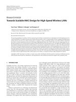
To ensure single-clock-cycle operation of the processing elements without introducing additional delays, simultaneous reading of inputs and writing of outputs in a single clock cycle is sought. Although a register-based architecture, proposed in [7] for the line decoder , could be a straightforward solution, preliminary synthesis results revealed routing and multiplexing challenges, especially for very large code lengths needed by polar codes. Instead, a parallel access approach using random access memory (RAM) is proposed. In a polar codes decoder, PEs consume twice as much information as they produce. Therefore, the semi-parallel architecture employs a dual-port RAM with a write port of width 𝑃𝑄 and a read port of width 2𝑃𝑄, along with a specific data placement in memory. This RAM-based approach not only meets the operational requirements but also reduces the area per stored bit compared to the register-based approach.
Figure 3-4 Mirrored decoding graph for N=8
</div>