the utilization of black liquor generated in the cellulose production in the synthesis of carbon based materials
Bạn đang xem bản rút gọn của tài liệu. Xem và tải ngay bản đầy đủ của tài liệu tại đây (5.08 MB, 115 trang )
<span class="text_page_counter">Trang 2</span><div class="page_container" data-page="2">
Supervisor: Assoc. Prof. Le Thi Kim Phung
Examiner 1: Assoc. Prof. Nguyen Truong Son
Examiner 2: Dr. Tran Phuoc Nhat Uyen
This master’s thesis is defended at Ho Chi Minh City University of Technology,
VNU-HCM on January 20<small>th</small>, 2024. Master’s Thesis Committee:
1. Chairman: Assoc. Prof. Nguyen Thi Phuong Phong
2. Examiner: Assoc. Prof. Nguyen Truong Son
3. Examminer: Dr. Tran Phuoc Nhat Uyen
4. Member: Assoc. Prof. Tran Tan Viet
5. Secretary: Dr. Le Vu Ha
Approval of the Chairman of the Master’s Thesis Committee and Dean of Faculty
of Chemical Engineering after the thesis was corrected.
CHAIRMAN OF THESIS COMMITTEE
DEAN OF FACULTY OF CHEMICAL ENGINEERING
</div><span class="text_page_counter">Trang 3</span><div class="page_container" data-page="3"><small>VIETNAM NATIONAL UNIVERSITY – HO CHI MINH CITY HO CHI MINH CITY UNIVERSITY OF TECHNOLOGY </small>
<small>─────────────────────────────── </small>
<small>SOCIALIST REPUBLIC OF VIETNAM Independence – Freedom – Happiness </small>
<small>────────────────── </small>
APPROVAL OF MASTER’S DISSERTATION
<small>- Synthesis and characterization of carbonized lignin-silica hybrids (CLS); Investigation into the effect of pH value (3 and 9) on the electrochemical behavior of CLS samples as an anode of lithium-ion battery. </small>
<small>- Synthesis chẩcterization of carbonized MFC aerogel (C-MFCA); Investigation of the electrochemical behavior of CLS samples as an anode of lithium-ion battery. </small>
<small>Phase 2: </small>
<small>- Fabrication and characterization of lignin/chitosan film with different lignin content; Evaluation of the UV blocking, antioxidant performance, and antibacterial activity of lignin/chitosan film. </small>
<small>3. Start date: 4th September, 2023 4. Finish date: 4th January, 2024 </small>
<small>5. Supervisor: Assoc. Prof. Le Thi Kim Phung </small>
<small>Ho Chi Minh City, January 11th 2024 SUPERVISOR </small>
<small>PGS. TS. Lê Thị Kim Phụng </small>
<small>HEAD OF DEPARTMENT </small>
<small>PGS. TS. Lê Thị Kim Phụng DEAN OF FACULTY OF CHEMICAL ENGINEERING </small>
</div><span class="text_page_counter">Trang 4</span><div class="page_container" data-page="4">ACKNOWLEDGEMENT
First of all, I would like to deliver many thanks to Ho Chi Minh City University of Technology, Faculty of Chemical Engineering, and especially Refinery and Petrochemical Technology Research Center (RPTC) for creating such precious opportunities for me to take my thesis project.
Most importantly, I would like to express my sincerest gratitude to my supervisor, Assoc. Prof. Le Thi Kim Phung, who always wholeheartedly supports me not only in terms of academic issues but also with her thoughtful encouragement. Even though there were several times that I squeezed her last drop of patience, she would still help me to work on my problems in such a moderate manner. Moreover, I would also like to send my thankfulness to PhD student Le Minh Tan and PhD student Do Nguyen Hoang Nga, the kind and passionate researchers, who were always ready to answer my chemistry questions. More than knowledge or surprising gifts, the “things” you two lied in me were the positive change in awareness, skills as well as heartfelt appreciation.
Although there were countless moments for me to feel grateful about during the thesis period, the occasion to know and work with my team was the most priceless. Thanks to you all, Boi Tuyen, Thanh Viet, and Trang Nhi, my senior year was full of memorial stories. Each member left in me deep impressions with a very special sensation.
Last but not least, I would like to say my biggest thanks to my wife and my family, who always supported me in various aspects and have been my most reliable foundation.
Pham Dang Co
</div><span class="text_page_counter">Trang 5</span><div class="page_container" data-page="5">ABSTRACT
Nowadays, the necessity of sustainable development in manufacturing is increasingly emphasized. In this setting, value-added byproducts from agriculture, waste-free processes, and efficient utilization of raw materials are considered to play a crucial role. Inspired by previous research on rice-straw-generated cellulose and the utilization of black liquor, this work focused on the extreme exploitation of rice straw for the production of various valuable materials. The first stage was the production of micro-fibrillated cellulose (MFC) from straw, which was further synthesized into MFC aerogel carbon material applied in the anode of lithium-ion batteries. The second stage was the utilization of black liquor generated from stage one in the production of lignin-silica carbon material (CLS), which was also used for anode fabrication. The last stage was the extraction of lignin from the black liquor after stage two. This material was then combined with chitosan to produce food preservation film. The results indicate that with a structure comprising carbon acting as a buffer layer and silica particles, CLS showed significant potential in synthesizing lithium-ion battery anode, possessing a specific charge capacity of 1668 mAh/g in the first cycle and maintaining stability at around 328 mAh/g after 100 cycles. Although demonstrating notable properties, the MFC aerogel carbon material only achieved a specific charge capacity of 258 mAh/g with equivalent Coulombic efficiency. In the field of food preservation, the obtained lignin/chitosan film exhibited 100% UV blocking, over 90% DPPH scavenging, and great antibacterial properties against E. Coli and C. Abicans. Based on these results, it could be concluded that alongside cellulose, secondary products such as lignin-silica could also be considered as prospective candidates to be applied in energy storage systems and food preservation issues.
</div><span class="text_page_counter">Trang 6</span><div class="page_container" data-page="6">TÓM TẮT
Ngày nay, sự cần thiết của phát triển bền vững trong sản xuất đang ngày càng được coi trọng. Trong bối cảnh này, việc tăng giá trị của các phụ phẩm từ nơng nghiệp, phát triển các quy trình không phát thải hay việc tận dụng triệt để nguồn ngun liệu đóng vai trị rất quan trọng. Dựa trên các nghiên cứu trước đây về việc sản xuất cellulose từ rơm rạ và việc tận dụng dịch đen, luận văn này tập trung vào việc khai thác triệt để nguồn nguyên liệu rơm rạ trong việc sản xuất nhiều vật liệu giá trị khác nhau. Giai đoạn đầu tiên là sản xuất micro-cellulose (MFC) từ rơm, tiếp tục phát triển từ vật liệu này thành vật liệu carbon MFC aerogel, ứng dụng trong chế tạo cực âm của pin lithium-ion. Giai đoạn thứ hai là quá trình sản xuất vật liệu carbon lignin-silica (CLS) sử dụng dịch đen từ giai đoạn một, vật liệu này cũng được sử dụng trong sản xuất điện cực. Giai đoạn cuối cùng là chiết tách lignin từ dịch đen của giai đoạn hai. Vật liệu này sau đó được kết hợp với chitosan để sản xuất màng bảo quản thực phẩm. Kết quả cho thấy với cấu trúc bao gồm nền carbon và các hạt silica, vật liệu carbon lignin-silica (CLS) đã thể hiện được những tiềm năng nổi bật trong việc tổng hợp cực âm pin lithium khi dung lượng nạp riêng đạt 1668 mAh/g trong chu kỳ đầu tiên và ổn định ở khoảng 328 mAh/g sau 100 chu kỳ. Dù cũng cho thấy những tính chất đáng chú ý, nhưng vật liệu carbon MFC aerogel chỉ đạt dung lượng nạp riêng 258 mAh/g nhưng với hiệu suất Coulomb tương đương. Trong lĩnh vực màng bảo quản thực phẩm, màng lignin/chitosan cho thấy khảng năng chống 100% tia UV, kháng DPPH trên 90% cùng khả năng kháng khuẩn E. Coli và nấm C. Abicans tốt. Từ những kết quả trên, bên cạnh cellulose, các sản phẩm phụ như lignin-silica cũng thể hiện khả năng ứng dụng tốt trong việc tiếp cận các vấn đề năng lượng và bảo quản thực phẩm.
</div><span class="text_page_counter">Trang 7</span><div class="page_container" data-page="7">GUARANTEE
I hereby declare that I am the sole individual who was responsible for the workload in this thesis, under the supervision of Assoc. Prof. Le Thi Kim Phung, at Refinery and Petrochemical Technology Research Center (RPTC), Ho Chi Minh City University of Technology, VNU-HCM.
The data and experimental results in this thesis were completely authentic and have not been published in any other dissertations of the same academic level.
If the above declaration is not true, I will take full responsibility for my thesis.
Ho Chi Minh City, January 2024 Author
Pham Dang Co
</div><span class="text_page_counter">Trang 8</span><div class="page_container" data-page="8">LIST OF TABLES --- xii
LIST OF ABBREVIATIONS --- xiii
CHAPTER 1: LITERATURE REVIEW --- 1
1.1. Rice straw and its agricultural advantages --- 1
1.1.1. Properties of rice straw --- 1
1.1.2. Current developments --- 4
1.2. Black liquor and lignin-silica composite from rice straw --- 6
1.2.1. Black liquor from rice straw --- 6
1.2.2. Lignin-silica composite from black liquor --- 9
1.2.3. Carbon materials derived from lignin --- 12
1.3. Introduction of micro-fibrillated cellulose (MFC) --- 16
1.3.1. Micro-fibrillated cellulose --- 16
1.3.2. The fabrication process --- 18
1.4. Lignin and cellulose-based electrodes --- 24
1.4.1. Working mechanism of lithium-ion batteries --- 24
</div><span class="text_page_counter">Trang 9</span><div class="page_container" data-page="9">1.4.2. Lignin-based electrodes --- 25
1.4.3. Cellulose-based electrodes --- 29
1.5. Application of lignin in food preservation --- 32
1.5.1. Superior properties of lignin in food packaging film --- 32
1.5.2. Chitosan-lignin composite in food packaging film --- 36
1.6. Motivations and objectives --- 40
CHAPTER 2: EXPERIMENTAL SECTION --- 41
(C-2.4.3. Preparation of lignin/chitosan film --- 48
CHAPTER 3: PERFORMANCE OF CELLULOSE AND LIGNIN-BASED MATERIALS IN THE ANODE OF LITHIUM-ION BATTERY--- 50
3.1. Structural characteristics of carbon materials --- 50
3.1.1. Characterization of carbonized lignin-silica (CLS) --- 50
3.1.2. Characterization of carbon micro-fibrillated cellulose aerogel (C-MFCA) --- 56
</div><span class="text_page_counter">Trang 10</span><div class="page_container" data-page="10">3.2. Behavior of CLS samples and carbon aerogel as anode in lithium-ion
4.2.3. Antibacterial and antifungal activity --- 78
CHAPTER 5: CONCLUSIONS AND RECOMMENDATIONS --- 81
</div><span class="text_page_counter">Trang 11</span><div class="page_container" data-page="11">LIST OF FIGURES
Figure 1.1. Structure of lignin ... 8
Figure 1.2. Solubility of silica depending on temperature ... 9
Figure 1.3. Lignin-silica linkage in plant ... 11
Figure 1.4. The mechanism of lignin pyrolysis process ... 14
Figure 1.5. Water phase diagram ... 20
Figure 1.6. FE-SEM images of the developed PF aerogels with different PF concentrations of (a) 0.5 wt.%, (b) 1.0 wt.%, (c) 2.0 wt.%, (d) water contact angles of the sample ... 22
Figure 1.7. Densities and porosities of pineapple leaf fibers aerogel with various fiber concentrations ... 23
Figure 1.8. Electrochemical performance of lignin-based anode and non-lignin-based anode: (a) cycle performance of the lignin-derived carbon anodes and lignin-free anodes, and charge-discharge pro f iles of (b) carbonized cellulose and lignin/cellulose (E-KL/CA-C, E-CA-C) at 50 mA g 1, (c) Si and lignin/Si(Si with lignin-derived carbon composite) at 0.1 A/g, (d) carbonized lignin with/without KOH treatment at 200 mA g 1, and (e) carbonized lignin with/without nitrogen doping 25 mA/g ... 27
Figure 1.9. Cellulose-based electrode materials for Li-Ion batteries (A) cellulose paper lamination technique for free-standing electrode (B) Meyer rod coating technique for CNT attached to commercial cellulose paper (C) Free-standing SnS /carbonized cellulose anode material for LIBs (D) flexible free-standing LTO/CNF/CNT anode paper (E) Plasma modified water-soluble cellulose-based electrodes for stable cycling of aqueous Li-ion batteries (F) 3D printing of NFC + CNTs for stretchable electrode assembly ... 31
Figure 1.10. UV absorption spectra of different chromophores in lignin ... 35
Figure 1.11. Absorbance at wavelengths 200−800 nm with different lignin concentration %w/w ... 35
</div><span class="text_page_counter">Trang 12</span><div class="page_container" data-page="12">Figure 1.12. Chitosan and lignin cross-linking structure ... 38
Figure 1.13. The mechanism of DPPH scavenging process of lignin... 39
Figure 3.1. FT-IR spectra of LS samples ... 50
Figure 3.2. FT-IR spectra of CLS samples ... 51
Figure 3.3. XRD patterns of CLS samples ... 52
Figure 3.4. SEM/EDX results of CLS samples ... 53
Figure 3.5. Isotherm adsorption of (a) LS3, (b) CLS3, (c) LS9, and (d) CLS9 ... 55
Figure 3.6. FT-IR spectra of MFC, MFCA, and C-MFCA ... 56
Figure 3.7. The bonding of PAE and MFC after annealing stage ... 57
Figure 3.8. SEM micrographs of CA (a,b) and CCA (c,d) ... 58
Figure 3.9. The EDX-mapping result of carbon, oxygen, and nitrogen in CA (a,b, and c) and CCA (d,e, and f) ... 59
Figure 3.10. Galvanostatic Charge–Discharge profile for a CLS3, b CLS9 at a current density of 1C after 100 cycles ... 60
Figure 3.11. Cycle performance of carbonized lignin-silica samples at 1C after 100 cycles ... 62
Figure 3.12. Galvanostatic Charge–Discharge profile for C-MFCA at a current density of 1C at the 1<small>st</small>, 2<small>nd</small>, and 100<small>th</small> cycle ... 64
Figure 3.13. The pulverization and SEI formation in lithium-ion battery ... 64
Figure 3.14. Cycle performance of C-MFCA samples at 1C after 100 cycles ... 65
Figure 3.15. Comparison of the performance of different types of carbon materials in lithium-ion batteries in this work ... 66
Figure 4.1: SEM micrographs lignin (a), chitosan film (b), LN1 (c), LN2(d), LN4(e), LN(f), and LN8 (g) ... 69
Figure 4.2: X-ray diffraction patterns of lignin, blank film, and LN2 (a), and FTIR spectra of lignin, blank sample, and LN2 sample (b) ... 70
Figure 4.3. TGA profiles of different lignin/chitosan film samples... 72
Figure 4.4: Water vapor permeability of the sample films... 73
Figure 4.5: UV blocking activity of lignin/chitosan film ... 75
</div><span class="text_page_counter">Trang 13</span><div class="page_container" data-page="13">Figure 4.6: UV transmittance of film samples with the wavelength in a range of
200-700 nm (a )and opacity of the film samples (b) ... 76
Figure 4.7: DPPH scavenging activity of different film samples. ... 77
Figure 4.8: The mechanism of DPPH scavenging process of lignin ... 78
Figure 4.9: The antibacterial mechanism of lignin ... 79
</div><span class="text_page_counter">Trang 14</span><div class="page_container" data-page="14">LIST OF SCHEMES
Scheme 2-1. Synthesis process of lignin/silica composite from rice straw ... 46
Scheme 2-2. The general synthesis of CLS samples ... 47
Scheme 2-3. Schematic for synthesizing MFC carbon aerogel ... 48
Scheme 2-4. Scheme of preparing lignin from rice straw... 48
Scheme 2-5. The general synthesis of lignin/chitosan film ... 49
</div><span class="text_page_counter">Trang 15</span><div class="page_container" data-page="15">LIST OF TABLES
Table 1-1. Lignocellulose contents in 4 different types of biomass [2]... 2
Table 1-2 Proximate composition and selected major elements of ash in rice straw, rice husk, and wheat straw [3] ... 2
Table 1-3. Comparison of some drying methods ... 20
Table 1-4. Advanced multi-properties of the cellulose aerogels ... 24
Table 2-1. List of chemicals purchased and used in the study ... 43
Table 3-1. Specific surface area and average pore diameter of LS and CLS samples ... 54
Table 3-2. BET surface area of CLS constituents ... 55
Table 3-3. The comparison of the elemental composition, specific surface area, and porosity of MFCA and C-MFCA ... 59
Table 3-4. Specific capacity of carbonized lignin-silica constituents ... 61
Table 3-5. The comparison of the performance of various materials from previous research as the anode in the LIBs ... 66
Table 4-1: Thickness, water solubility, and moisture content of the film samples .... 67
Table 4-2: Mechanical strength of film samples ... 73
Table 4-3. Comparison of UV blocking efficiency of different agents ... 75
Table 4-4: Inhibition rate of LN0 and LN2 film for E. Coli and C. Abicans and MIC value of LN2 ... 78
Table 4-5: Comparison of antifungal activity of different agents ... 80
</div><span class="text_page_counter">Trang 16</span><div class="page_container" data-page="16">LIST OF ABBREVIATIONS
BET Brunauer-Emmet-Teller CLS Carbonized lignin-silica
C-MFCA Carbonized micro-fibrillated cellulose aerogel DPPH 2,2-diphenyl-1-picrylhydrazyl
FT-IR Fourier-transform infrared spectroscopy GCD Galvanostatic charge/discharge
LN Lignin/chitosan film LS Lignin-silica
</div><span class="text_page_counter">Trang 17</span><div class="page_container" data-page="17">CHAPTER 1: LITERATURE REVIEW
1.1. Rice straw and its agricultural advantages
Rice straw serves multiple agricultural purposes, encompassing applications such as mulching, green manure, and livestock bedding. Studies in Vietnam show that rice straw mulch can reduce soil evaporation by up to 20% [1] and inhibit weed growth by about 70%. Incorporating rice straw into the soil as green manure increases soil organic carbon content, enhances nutrient availability, and boosts crop yields. Adding 5 to 8 tons of rice straw per hectare as green manure can increase rice yields by 10 to 15%. Rice straw is also used as supplementary livestock feed, especially when combined with other nutrient-rich sources, improving livestock performance, and reducing feed costs. Dairy cattle fed with rice straw exhibit enhanced milk production and reduced feed expenses by up to 30%. Additionally, rice straw serves as a bedding material, improving livestock comfort, moisture absorption, and waste management. Therefore, the incorporation of this type of biomass into agricultural systems promotes nutrient cycling and carbon sequestration, facilitating the release of essential nutrients and mitigating greenhouse gas emissions.
1.1.1. Properties of rice straw Chemical composition
Chemical composition determines the nutritional quality of rice straw, which is important for livestock feed, anaerobic digestion, and soil amendment. Rice straw has low nutritional value and research has been done to improve it. Jenkins (1998) indicated that the typical components of plant biomass are moisture cellulose, hemicelluloses, lignin, lipids, proteins, simple sugars, starches, water, hydrocarbon, ash, and other compounds. The concentrations of these compounds depend on the plant species, type of tissue, growth stage, and growing conditions. Rice straw is considered a lignocellulosic biomass that contains 38% cellulose, 25% hemicellulose, and 12% lignin. Compared to the biomass of other plants, such as softwood, rice straw
</div><span class="text_page_counter">Trang 18</span><div class="page_container" data-page="18">is lower in cellulose and lignin and higher in hemicellulose content. Table 1-1 shows the comparison of rice straw with other biomass sources.
Table 1-1. Lignocellulose contents in 4 different types of biomass [2]
Rice straw <sup>Pineapple </sup>
leaves <sup>Wheat straw </sup> <sup>Coco-peat </sup>
</div><span class="text_page_counter">Trang 19</span><div class="page_container" data-page="19">The chemical composition of feedstock has a major influence on the efficiency of bioenergy generation. Table 1-2, Lists the chemical properties (fuel properties) of three agricultural residues: rice straw, rice husk, and wheat straw to highlight the particulate differences in feedstock. Rice straw has low-quality feedstock primarily determined by a high ash content (10 - 17%) as compared to wheat straw (around 3%) and high silica content in ash in rice (SO<small>2</small> is 75%) straw and in wheat 55%. On the contrary rice straw feedstock has relatively low total alkali content (Na<small>2</small>O and K<small>2</small>O comprise < 15% of total ash) whereas wheat straws have < 25 alkali content in ash. Based on its slagging index, Rs 0.04, fouling index, Rf 0.24. Rice straw is not expected to have significant operating problems or different emissions compared with wheat straw and rice husk under similar operating conditions. Rice husk which is also of poor feed quality, is caused mainly by high silica content, but its uniformity in size and easy procurement are advantages. Thus the preferred use of this biomass for energy is related to both availability and quality.
Thermal properties
The calorific value is an essential parameter that shows the energy value of rice straw if to be used for bioenergy. The energy efficiency of rice straw can be calculated by dividing its energy output by its calorific value, which may be expressed as the higher-heating value (HHV), wherein latent heat of the water is included, or lower-heating value (LHV). In terms of calorific value, rice straw has an HHV that ranges from 14.08 to 15.09 MJ kg<small>−1</small> [3], as determined by different studies. Fixed carbon refers to the carbon left after the volatiles are driven off. Rice straw has a fixed carbon ranging from 11.10% to 16.75%, which is also comparable to other biomass. The ultimate analysis reveals the elemental carbon, hydrogen, oxygen, nitrogen, and sulfur composition of rice straw. In contrast to fossil fuels, rice straw biomass has a lower carbon content, but higher oxygen and hydrogen contents. The ash content of rice straw, comprising noncombustible residues, ranges from 18.67% to 29.1% [3]. The elevated silica content in rice straw poses challenges in processing machinery, such as conveyors and grinders, as well as in boilers. Additionally, it diminishes the
</div><span class="text_page_counter">Trang 20</span><div class="page_container" data-page="20">digestibility of rice straw when utilized as fodder. Compared to wood and coal, rice straw exhibits a higher volatile matter and a lower fixed carbon content. The substantial ash content in rice straw not only reduces its calorific value but also poses challenges in energy conversion processes. The significant potassium and alkali content in the ash can contribute to corrosion and fouling issues in grates, as alkali metals are recognized catalysts for these phenomena.
1.1.2. Current developments Agricultural applications
Rice straw has various agricultural uses, including mulching, green manure, and livestock bedding. Its utilization provides benefits such as soil moisture conservation, weed suppression, improved soil fertility, and nutrient cycling. Studies in Vietnam show that rice straw mulch can reduce soil evaporation by up to 20% [4] and inhibit weed growth by about 70%. Incorporating rice straw into the soil as green manure increases soil organic carbon content, enhances nutrient availability, and boosts crop yields. Adding 5 to 8 tons of rice straw per hectare as green manure can increase rice yields by 10 to 15%. Rice straw is also used as supplementary livestock feed, especially when combined with other nutrient-rich sources, improving livestock performance and reducing feed costs. Dairy cattle fed with rice straw exhibit enhanced milk production and reduced feed expenses by up to 30%. Additionally, rice straw serves as a bedding material, improving livestock comfort, moisture absorption, and waste management. Its incorporation into agricultural systems promotes nutrient cycling and carbon sequestration, facilitating the release of essential nutrients and mitigating greenhouse gas emissions.
Energy Production
Rice straw has great potential as a feedstock for renewable energy production, specifically in biogas generation and bioethanol production. Biogas yield from rice straw can range from 120 to 160 cubic meters per metric ton [5], offering a clean energy source and waste management benefits. Rice straw can also be converted into
</div><span class="text_page_counter">Trang 21</span><div class="page_container" data-page="21">bioethanol, with a yield of approximately 200 liters per metric ton [6], reducing greenhouse gas emissions compared to fossil fuels. Moreover, rice straw can fuel biomass power plants, generating electricity at capacities ranging from 1 to 10 megawatts [7]. This renewable energy utilization of rice straw reduces reliance on fossil fuels, mitigates climate change, improves air quality by avoiding open burning, and contributes to rural electrification. However, challenges such as collection, transportation, and technological advancements need to be addressed. Further research, infrastructure development, and supportive policies are essential to fully harness the potential of rice straw for sustainable energy production in Vietnam.
Value-Added Products
Innovative applications of rice straw can transform it into value-added products, minimizing waste and creating economic opportunities. This section explores specific data on the utilization of rice straw in the production of biochar, compost, and mushroom cultivation. It highlights the environmental and economic benefits of these value-added products, such as carbon sequestration, soil improvement, and the creation of alternative revenue streams. A very popular product that is derivative from rice straw is biochar which can be known as a carbon-rich material produced through the pyrolysis of biomass. Research studies conducted in Vietnam demonstrate the potential of rice straw biochar in improving soil fertility and carbon sequestration. Specific data reveals that biochar produced from rice straw can have a carbon content ranging from 30% to 40%, making it a valuable soil amendment [8]. Furthermore, the addition of rice straw biochar to the soil can enhance water retention, nutrient availability, and overall soil health. Moreover, lignin and silica can be extracted from rice straw, offering valuable components for various industries. Lignin has applications in renewable chemicals, bioplastics, and biofuels, reducing reliance on non-renewable resources. Silica, abundant in rice straw, is used in construction, electronics, and agriculture. Its extraction from rice straw creates value-added products and reduces environmental impact. Research and development efforts continue to optimize extraction techniques and explore new applications for these
</div><span class="text_page_counter">Trang 22</span><div class="page_container" data-page="22">components such as dye pollution treatment by adsorption method, promoting their use in a range of industries.
1.2. Black liquor and lignin-silica composite from rice straw
1.2.1. Black liquor from rice straw
Black liquor, commonly known as a waste product of the paper pulping industry process, is a mixture containing mostly lignin, cellulose, hemicellulose, and many other organic and inorganic compounds recovered after the separation of cellulose from the structure of lignocellulose materials. Throughout many years of development history, this waste stream has been treated simply by burning as fuels for the generation of steam and electricity in the paper industry [9]. Realizing the urgent environmental problems, it was not until recent decades that many studies related to the use of black liquor as a raw material in the production of advanced biofuels and biochemicals have been implemented, especially in countries with strong policies that support the development of renewable energy and the bioeconomy. In the European Union, the Renewable Energy Policy requires its member to increase the share of renewable energy in their transport sector to 10% by 2020 and up to 14% by 2030 [10]. Accordingly, black liquor is considered a potential candidate that can meet these goals. To date, several research projects and pilot plants have been conducted to test the feasibility of using black liquor for this purpose. In the United States, black liquor is also considered as a potential raw material for the production of value-added products. The Renewable Fuels Standards Program, established under the Energy Policy Act of 2005, requires a certain amount of renewable fuels to be blended into transportation fuels each year and black liquor is again a source of material that can be used to fulfill these requirements.
However, up until this recent decade, black liquor was still only utilized in the paper industry, until the concept of biorefinery was being developed. Black liquor recovered from the alkali pretreatment process of straw biomass contains significant amounts of silica and lignin (25.14% and 51.81% respectively) [11]. Therein, lignin is a highly branched polymer with an amorphous structure and a molecular weight of
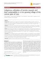
</div><span class="text_page_counter">Trang 23</span><div class="page_container" data-page="23">1000 to 20000 g/mol. This polymer is made up of monolignol, also known as lignol, which is all derived from phenylpropane: coniferyl alcohol (4-hydroxy-3-methoxyphenylpropane) (G or guaiacyl), sinapyl alcohol (3,5-dimethoxy-4-hydroxyphenylpropane) (S or syringyl), and paracoumaryl alcohol (4-hydroxyphenylpropane) (H or 4-hydroxyphenyl) (Figure 1.1). The proportions of these monomer precursors vary by plant origin: hardwoods and grasses are rich in coniferyl and sinapyl units, and softwoods are rich in conifery units. All lignins contain small amounts of incomplete or modified lignols, and other monomers (which are abundant in non-woody plants) [12]. Natural lignin is usually colorless or pale yellow, but after treatment with acid or alkali, its color tends to change into brown or dark brown. Owing to the structure of a chain of non-polar aromatic rings, lignin is almost insoluble in water or polar solvents and even in concentrated H<small>2</small>SO<small>4</small> acids but becomes easy to be dissolved in hot alkalis solution due to the presence of phenolic hydroxyl groups. In addition, this organic compound exhibits great solubility in organic solvents such as ethanol, tetrahydrofuran, or dimethyl sulfoxide. The diverse number of functional groups including free phenolic hydroxyl, methoxy, benzylic hydroxyl, benzylic, or phenolic ethers with linear alcohols and carbonyl groups leads to compatibility with a wide range of industrial chemicals. Lignin demonstrates similar properties and advantages to those of other renewable biopolymers including antioxidant, anti-fungal, and antibacterial activities, availability in large quantities as a by-product from industrial waste, and biodegradable [13].
</div><span class="text_page_counter">Trang 24</span><div class="page_container" data-page="24">Figure 1.1. Structure of lignin
With these mentioned properties, lignin from lignocellulose structure can be applied directly without any further chemical modification and is able to be used as a component or filler in thermoplastics as a UV radiation stabilizer, antioxidant, flame retardant, and additive to promote product plasticity and flowability. On the other hand, in some cases, this compound has been chemically modified, in which lignin undergoes the depolymerization process to form base compounds such as aromatics, alkanes, phenols, and derivatives – the input source for polymer synthesis or to produce chemicals, fuels, and high-value products [14].
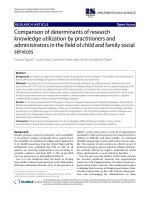
During the black liquor treatment process, silica holds a significant proportion of the recovered solid, which is generated through the absorption of water-soluble silicic acid (H<small>4</small>SiO<small>4</small>) combined with polymerization reactions to form insoluble polysilicic acid, then precipitating as amorphous silica and depositing in the plant cell wall [15]. In terms of properties, the solubility of silica is a temperature-dependent ability; as shown in Figure 1.2, this value peaks at 340 °C [16]. In particular, silica can react with alkalis and base oxides at high temperatures to create a solution of silicate salt. [17]
</div><span class="text_page_counter">Trang 25</span><div class="page_container" data-page="25">Figure 1.2. Solubility of silica depending on temperature
The thermal stability of silica is significantly greater than cellulose, hemicellulose, and lignin, with a melting point of 1713 °C. Furthermore, amorphous silica obtained from biomass has a large specific surface area, which can be up to 580 m<small>2</small>/g [18]. Therefore, silica is one of the most important components and can be found in various fields such as biological materials production, environmental treatment, construction, synthesis of composite materials, and the production of medical devices [19]. The main reason for the wide range of applications of silica could be deduced by the unique properties of this material relating to its chemical, physical, and thermal stability, its compatibility with numerous materials, and its availability (existing in agricultural by-products) with reasonable prices.
1.2.2. Lignin-silica composite from black liquor
In recent years, a new approach towards biorefinery of agricultural by-products has been introduced as a ‘lignin-first approach’ with the concept of reducing the depolymerization of lignin as the key factor in consideration [20]. This approach may provide both an enhanced property of recovered lignin and provide a better framework for holocellulose production.
With the applicability of lignin/silica composite as mentioned above, many efforts have been conducted to find out the methods to extract lignin and silica from
</div><span class="text_page_counter">Trang 26</span><div class="page_container" data-page="26">black liquor and combine it to become a valuable composite. In which, some methods have successfully taken advantage to prepare lignin/silica hybrids such as solvent blending or in-situ polymerization methods [21]–[24]. In the solvent blending method, lignin is dissolved in a solvent, and silica particles are dispersed in the solution. After removing the solvent, the lignin/silica composite is obtained. When it comes to in-situ polymerization, monomers are polymerized in the presence of lignin and silica, creating a composite with a chemically bonded polymer matrix. These methods enable the synthesis of lignin/silica composites with tailored properties and diverse applications. Overall, these mentioned methods require a complex process and specific chemicals to conduct the operation for preparing lignin/silica composite. Hence, it is necessary to find novel methods that could overcome all these aforementioned drawbacks. In the journey of seeking alternative processes, the sol-gel method can satisfy all requirements to assure the evaluative criteria of product quality and environmental safety. During this process, the composite is co-precipitated with sulfuric acid H<small>2</small>SO<small>4</small> solution for simple production capable of industrial applications. Specifically, in a previous publication by our research group [25], lignin-silica materials were synthesized through an acidification step to adjust the pH of the black liquor after the alkali treatment of rice straw from a value of 12 to values of 9 and 3. By combining other analysis methods, including XRD, SEM, and FTIR, the material was proven to consist of silica particles deposited on lignin chains, as well as chemical bonds between these two substances.
Many studies have shown evidence of a chemical connection between lignin and silicon in plants, including FTIR adsorption band of 940 cm<small>−1</small> indicating a connection between Si-O and lignin (Figure 1.3a) and Raman scan of a strong band of 973 and 802 cm<small>−1</small>, suggesting a Si-O-Si and Si-C connection [26]. In another study, silicon connection with organic compounds was proposed to include 3 possible linkages: phosphoryl, carboxyl, and hydroxyl connection [27]. Biological studies propose the idea of the hydroxyl group in lignin, tannin, and polysaccharides of plants crosslinking with monosilicic acid [28], supporting the previous hypothesis. Until
</div><span class="text_page_counter">Trang 27</span><div class="page_container" data-page="27">recently, these assumptions of the exact connection and mechanism of formation between lignin and silica bonds remained unclear until one research precipitates lignin and silica simultaneously and evaluates any chemical bond changes in NMR.
<small>29</small>Si SP/MAS NMR spectra of silica – lignin precipitated compounds display the formation of hydrogen bonds (Figure 1.3b) – which is believed to be the main connection between silanol groups. The formation of hydrogen bonds is caused by the substitution mechanism between lignin and silica, which is suggested by the differences in the distribution of hydroxyl groups before and after on silica surfaces.
Figure 1.3. Lignin-silica linkage in plant
Besides, other studies have indicated that lignin-silica samples synthesized through this method may exhibit variations in the silica and lignin content (with silica content being four times higher than the lignin content [29] and silica particle diameter of over 1000 nm [30]. This can be explained by the complex branching structure of lignin, which may differ depending on the specific biomass source and the influence of the surrounding environment. Similarly, silica particles in plants can vary from 5.69% to 9.95% in different growing seasons, and so on. Based on these findings, in-depth studies are needed to ensure the stability and essential properties of lignin-silica structures for each specific feedstock source, taking into account factors such as cultivation seasons, soil nutrient levels, initial biomass composition, and more.
</div><span class="text_page_counter">Trang 28</span><div class="page_container" data-page="28">1.2.3. Carbon materials derived from lignin
As mentioned above, lignin is a complex polymer containing diverse functional groups such as hydroxyl, methoxy, and phenolic groups. This diversity imparts chemical and mechanical properties to lignin when it is transformed into carbon materials. The complicated structure of lignin allows for the creation of carbon materials with diverse and tunable properties. For instance, through thermal or chemical treatments, this organic compound can be converted into different forms of carbon, such as activated carbon, carbon powder, or carbon fibers. The lignin network also affects the physical properties of carbon materials, including hardness, strength, flexibility, and electrical conductivity. The versatility and tunability of carbon materials from lignin open up numerous potential applications. For instance, carbon materials derived from lignin is able to be used in the production of lightweight, flexible, and sustainable construction materials. They can also be applied in the electronics industry and renewable energy applications such as lithium-ion batteries. However, the complex structure of lignin also requires more sophisticated production and processing methods to obtain high-quality carbon materials. Research and development of advanced technologies to take full advantage of lignin are important challenges for the development of carbon materials from renewable and sustainable sources.
Due to the high carbon content and abundant aromatic compounds, lignin is considered a suitable feedstock for carbon material production through various large-scale thermochemical processes. The fundamental principle of these processes involves depolymerizing lignin molecules and transforming them into biochar materials possessing aromatic hydrocarbon structures, with the assistance of catalysts, high temperatures, or high pressures. Recent studies have shown that there are common carbonization methods for lignin-derived materials, such as pyrolysis, hydrothermal carbonization, and plasma-assisted pyrolysis.
Composite material obtained from the pyrolysis route
Pyrolysis is the most common method for biomass material decomposition into carbon materials at high temperatures under an inert (such as N<small>2</small>, Ar) or non-reactive
</div><span class="text_page_counter">Trang 29</span><div class="page_container" data-page="29">gas atmosphere. The main pyrolysis products of lignin include biochar, bio-oil, and syngas. Specifically, for fast pyrolysis processes, lignin is mainly converted into bio-oil, whereas biochar is the primary product after the slow one [31]. Therefore, to obtain carbon materials with high carbon content from lignin, slow pyrolysis is usually conducted at temperatures ranging from 250 to 1000 °C, with heating rates gradually increasing from 5 to 50 °C/min [32]. Additionally, when discussing the carbon structure formation process, lignin undergoes four following stages [33]:
1. Drying (moisture removal)
2. Depolymerization: the evaporation of small lignin phenol molecules and other organic compounds, as well as the condensation of lignin phenol monomers
3. Restructuring of the carbon structure
Due to the effects of temperature during the carbonization process, the amounts of oxygen-containing functional groups such as carbonyl, carboxyl, and methoxy groups can be reduced, while a significant amount of aryl groups tend to be generated [34]. As a result, the amorphous carbon portion obtained from lignin has become more hydrophobic. Reports indicate that in some cases, with slow heating rates, the resulting carbon material has better hardness and preserved porous structure. Conversely, the porous structure of the obtained carbon material decreases, but it exhibits greater stiffness and stability with fast heating rates.
Regarding the production of carbon-silicon hybrid materials, the commonly applied method nowadays is thermal decomposition under inert conditions. However, there are several gaps in the research that have not been discussed. In the same method, current research is mainly considered as introducing new source materials rather than investigating the integration of different synthesis conditions. For example, it has been recognized that the carbonization temperature can influence the composition and structure of carbon during the production of biochar and silica during the synthesis of bio-silica. Variations in the heating rate have also been observed to affect the composition and surface area of carbon and silica materials during separate recovery processes [35]. Furthermore, the current method predominantly employs argon as the inert gas for the thermal decomposition process,
</div><span class="text_page_counter">Trang 30</span><div class="page_container" data-page="30">which may not be the most economical choice. Therefore, an alternative choice of inert gas should be introduced and studied for its impact on the resulting mixture. For instance, there have been limited studies addressing the use of nitrogen (N<small>2</small>) with the potential to produce Si<small>3</small>N<small>4</small> as a product of the nitration process of SiO<small>2</small> in the presence of carbon according to the reaction:
4SiO<sub>2</sub>(s)+8C(s)+2N<sub>2</sub>(g)→ SiC(s)+Si<sub>3</sub>N<sub>4</sub>(s)+8CO(g)
When these production conditions are further considered, the range of applications for carbon-silica hybrids will be expanded to become a solution for advanced technologies in the future.
Composite material obtained from hydrothermal carbonization route Hydrothermal carbonization is a process in which lignin is decomposed and carbonized in a pressurized vessel with water as the solvent. Compared to pyrolysis, hydrothermal carbonization is considered greener and more environmentally friendly due to lower carbonization temperatures and the absence of the release of harmful gas byproducts [36]. Typically, the hydrothermal process of lignin is conducted at temperatures ranging from 180 to 350 °C with pressures of 2-10 MPa. The resulting solid carbon material is commonly referred to as hydrochar. The formation of hydrochar mainly undergoes the following stages: hydrolysis, dehydration, decarboxylation, aromatization, and condensation, as depicted in Figure 1.4 [37]
Figure 1.4. The mechanism of the lignin pyrolysis process
In addition to hydrothermal carbonization, lignin can also be liquefied or gasified under various hydrothermal conditions. Higher hydrothermal temperatures or the addition of catalysts tend to favor lignin liquefaction, thus reducing the hydrochar
</div><span class="text_page_counter">Trang 31</span><div class="page_container" data-page="31">production yield [36]. In the publication conducted by Kang et al., it was found that the use of formaldehyde as a cross-linking agent facilitated the hydrothermal carbonization of black liquor, resulting in an increased hydrochar synthesis efficiency of 1.27 – 2.13 times while significantly reducing sulfur and ash content [38]. More recently, microwave-assisted hydrothermal carbonization technology has been reported to improve the reaction rate of lignin hydrothermal processes. Furthermore, this method is considered energy-efficient, environmentally friendly, and more effective compared to traditional hydrothermal carbonization methods [39].
Similarly to the pyrolysis method, the structure and morphology of carbon materials derived from lignin through hydrothermal carbonization are highly dependent on the type of lignin, hydrothermal temperature, and duration [40]. However, unlike carbon from pyrolysis, lignin hydrochar has higher H/C and O/C ratios as well as higher hydrophilicity, making it appropriate to be employed as a biofuel, adsorbent, catalyst support, precursor for activated carbon, and bioimaging agent [41]. When combined with high-temperature pyrolysis, lignin hydrochar is able to be further transformed into carbon materials with specific functionalities or structures. For example, under the catalytic effect of certain metal salts at 900–1100 °C, lignin hydrochar can be converted into highly conductive biochar to possess a graphitic structure [42]. Additionally, due to the presence of trace elements during high-temperature pyrolysis, lignin-derived carbon can also be utilized as a catalyst for biomass conversion and phenol removal [43]. Through high-temperature activation with KOH, lignin hydrochar can be transformed into high-quality activated carbon for CO<small>2</small> adsorption [44], pollutant treatment, etc.
From the above-mentioned reviews, it can be concluded that, at present, pyrolysis under inert conditions is evaluated as the simple, effective, and popular method for the production of carbon-silica hybrid materials. However, many issues surrounding this method have yet to be discussed. Investigations related to the pyrolysis environment are therefore beginning to be noticed and considered for improvement in the quality of the synthesized materials and the applicability of lignin-silica in various fields.
</div><span class="text_page_counter">Trang 32</span><div class="page_container" data-page="32">1.3. Introduction of micro-fibrillated cellulose (MFC)
1.3.1. Micro-fibrillated cellulose
MFC, also called cellulose microfibril, microfibrillar cellulose, has been reviewed quite recently, particularly in terms of nanocomposite applications [45]. Microcellulose fibers have an area network of bundled microfibrils, which form slender and seemingly infinite rods. When these microfibrils are dissolved in strong acids, they form cellulose microcrystals, which are short crystalline rods with a diameter of 9–16 μm [46]. MFC is manufactured by fibrillation of cellulose fibers into nanoscale components and requires a lot of mechanical treatment. Chemical treatments may be applied prior to mechanical fibrillation, depending on the raw material and the degree of processing. These chemical methods generate purified cellulose, such as bleached cellulose pulp, which can then be treated further. There are alternative ways with lower energy needs, such as enzymatic pre-treatment followed by mechanical treatments to isolate cellulose microfibrils.
Pretreatment of cellulose fibers is a technique for lowering the energy consumption of mechanical nanofibrillation procedures while increasing the degree of nanofibrillation. The pretreatment process has become a crucial step because energy expenditure is a large drawback for producing nanofibers [47].
Enzymatic pretreatments enable the manufacture of MFC using much less energy. In nature, cellulose is not degraded by a single enzyme, but a set of cellulases is included. These can be categorized as A- and B- type cellulases, also known as cellobiohydrolases, which may target highly crystalline cellulose; C- and D-type cellulases or endoglucanases which generally require some structural to degrade cellulose. Svagan et al. and López-Rubio et al. both used a combination of mechanical and enzymatic treatments [48]. The pulp was treated in four different processes to delaminate the cell walls: a refining step using an Escherwyss refiner to increase the accessibility of the cell wall to the subsequent enzyme treatment, an enzymatic treatment step with monocomponent endoglucanase, a second refining stage, and
</div><span class="text_page_counter">Trang 33</span><div class="page_container" data-page="33">finally a step where the pulp slurry was passed through a high-pressure microfluidizer.
Alkaline–acid pretreatment is the typical approach method for lignin, hemicellulose, and pectin solubilization removal before mechanical isolation of nanocellulose. The steps in this process were as follows: Firstly, the fibers were soaked in an alkaline solution. This raises the surface area of cellulosic fibers and facilitates the hydrolysis before immersing them in an acid solution; this process solubilizes the hemicelluloses. Finally, a greater concentration of alkaline solution is used. The lignin structure is disrupted, and the carbohydrate-lignin connections are broken [49].
MFC produced by mechanical treatments was first reported by Herrick et al. and Turbak et al. in 1983. Their methods were based on passing dilute cellulosic wood pulp-water solutions through a mechanical homogenizer with a large pressure drop to aid microfibrillation. MFC is currently a commercial product that can be purchased from various companies and other organizations (e.g. Rettenmaier, Germany; Daicel, Japan or Innventia AB, Sweden) [50]. Mechanical treatment, which includes high-pressure homogenization, microfluidization, grinding, cryocrushing, high-intensity ultrasonication, and ball milling, is currently used to create MFC, which is based on refining and high-pressure homogenizing process steps. The fibers undergo irreversible modifications as a result of the mechanical treatment, boosting their bonding potential by altering their shape and size [51]. Mechanical refining procedures, on the other hand, either damage the microfibril structure by lowering molar mass and degree of crystallinity or fail to disintegrate the pulp fiber enough. Due to the fact that the refining process causes exterior fibrillation of fibers by progressively peeling off the external cell wall layers, it is done before homogenization. Internal fibrillation loosens the fiber wall, allowing the pulp fibers to be homogenized thereafter [52].
</div><span class="text_page_counter">Trang 34</span><div class="page_container" data-page="34">1.3.2. The fabrication process
MFC is characterized by its high porosity, great absorbency, exceedingly low thermal conductivity, high strength-to-weight ratio, and large surface-to-volume surface. As a result, considerable research has been conducted to develop porous materials, such as aerogels, from this natural, renewable, and biodegradable cellulose resource. Also, various active substances can be immobilized in cellulosic substrates. Those characteristics of MFC are a consequence of its microstructure [53].
The cross-linking method employed during the gelation process has a significant impact on the final structure and performance of porous materials. Physical crosslinking is often based on weaker forces like hydrogen bonding and electrostatic interaction. Chemical crosslinking, on the other hand, frequently results in stronger interactions and networks, such as covalent bonding and polymerization. The most prevalent gelation technique is hydrogen bonding between nanocellulose or between nanocellulose and additional additives. Typically, electrostatic interactions usually occur between the negatively-charged nanocellulose and positively charged crosslinking agents. Divalent cations are commonly utilized to electrostatically generate ionic crosslinking between anionic nanocellulose. Covalent crosslinking is created by the action of covalent bonds to produce crosslinking between nanocellulose and reactive coupling agents. Both covalent and polymerization crosslinking produce gelation by forming new covalent bonds, considerably improving network mechanical strength [54].
Crosslinking via physical hydrogen bonding before freezing is widely adopted to achieve gelation [55]. Physical gelation of nanocellulose-based lightweight porous materials tends to show limited structural stability. Chemical gelation by covalent crosslinking, on the other hand, is more advantageous for improving mechanical performance. To achieve covalent gelation of nanocellulose, various crosslinking agents, such as maleic acid (MA), butane tetracarboxylic acid (BTCA) [56], polyamide epichlorohydrin (PAE) [57], γ-glycidopropyltrimethoxysilane (GPTMS) [58], methyltrimethoxysilane (MTMS) [59], dialdehyde starch [60], and 3-isocyanatopropyltriethoxysilane, etc. Zhang et al. [61] developed an NFC/MFC
</div><span class="text_page_counter">Trang 35</span><div class="page_container" data-page="35">aerogel with excellent wet strength by utilizing a PAE cross-linker that generated both self-crosslinking and external crosslinking with cellulose. The crosslinked aerogels with hierarchical pore structures absorbed a lot of water and recovered their shape in both air and water quickly. Guo et al. [62] prepared N-methylol dimethylphosphonopropionamide and BTCA as cross-linkers to create a flame-retardant NFC aerogel. The composite aerogel’s microstructure was comparable to that of the pure NFC aerogel, but the interlayer gap increased, and a more fibrous structure emerged at the interlayers. The composite aerogels exhibited exceptional ductility due to the development of covalent ester linkages between the hydroxyls of NFC and the carboxyls of BTCA. Cheng et al. covalently crosslinked a durable and flexible NFC cryogel using GPTMS and PEI. The highest shape recovery rate of NFC cryogel under 50% compression strain was as high as 93% of its original thickness due to the interaction of the polysiloxane layer and the high degree of cross-linking. Jiang et al. (2020) [63] combined CNF with MTMS and fumed silica with a simple method to create a porous and hydrophobic CNF aerogel with extremely low thermal conductivity (0.027 W.m<small>-1</small>.K), MTMS in the research functions as a crosslinker as well as a hydrophobic modifier.
Mainly, most freeze-dried nanocellulose aerogels are formed by immersing the precursor dispersion/gel directly into liquid nitrogen (-196 <small>o</small>C) or refrigeration (-18
<small>o</small>C). After sublimation, The ultralow liquid nitrogen leads the water solvent to form ice crystals quickly, leaving dense and small pores in the aerogel after sublimation. Especially, Because of the slower freezing rate, it takes longer to produce bigger pores when employing a cold source with a higher temperature. However, this traditional freezing method also presents limitations, mainly that the microporous structure of the aerogel is usually isotropic. The chaotic structure prohibits the aerogel from obtaining a directional mass transfer, heat transfer, electrical conductivity, and other functions.
The drying procedure is crucial for regulating and controlling pore structure. The common method for preparing nanocellulose-based aerogel is air-drying. However, it does has some serious issues, such as adhesion produced by solvent surface tension
</div><span class="text_page_counter">Trang 36</span><div class="page_container" data-page="36">and collapse of the internal network structure caused by capillary action of the solid matrix. In order to reduce these problems, freeze-drying can be used to cross the solid-gas boundary, which is known as sublimation. Sublimation is the process by which water alters its form from solid to vapor without passing the liquid phase at the Eutetti point on the diagram of water (Figure 1.5). The second method for avoiding the liquid-gas interface is to raise the temperature and pressure over the critical point, a process known as supercritical drying. Both freeze-drying and supercritical-drying can efficiently solve the aforementioned issues while retaining the porosity structure [64].
Figure 1.5. Water phase diagram
Additionally, the advantages and disadvantages of some drying methods are listed in Table 1-3 below:
Table 1-3. Comparison of some drying methods
` Criteria Requirement Limitation Cost/risk
Air-drying At
atmospheric pressure,
Often requires material structure to be hydrophobic
Only suitable for aerogel with
Low cost, easy to do
</div><span class="text_page_counter">Trang 37</span><div class="page_container" data-page="37">room pressure
density >0.1 g.cm<small>-3 </small>
drying
T>31<small>o</small>C, P>74 bar. Normally operating at 40 <small>o</small>C and 100–150 bar
The solvent must be compatible with CO<small>2</small> under the drying conditions of the process. The Hydrogels must exchange the solvent
The kinetic energy of the drying process depends on the exchange of CO<small>2</small>/solvent in/out to form the structure. This type of drying is suitable for gels
Suffer significant energy loss due to CO<small>2</small>
compression process, risk of explosion due to low-temperature combined with CO<small>2</small> high-pressure
drying
Freeze-Vacuum (P<100 mbar), -70<T<-20 °C
It is crucial to limit shrinkage and ensure the freezing point of the material
It is difficult to reach the goal of drying to a density of 0.03 g.cm<small>-3</small>.
High energy consumption due to the demand of maintaining a vacuum state
For instance, in Vietnam, the agricultural industry is one of the key contributors to developing the country. Along with a high population and birth rate, the increasing demand for food production results in massive waste generation. Those residues contribute to many environmental problems because they are disposed of by burning, left to decompose, or are landfilled directly. Because of their numerous supplies, biodegradability, and largely pollution-free agricultural waste, the creation of high-performance materials from agricultural waste has piqued the interest of researchers and government officials.
</div><span class="text_page_counter">Trang 38</span><div class="page_container" data-page="38">Figure 1.6. FE-SEM images of the developed PF aerogels with different PF concentrations of (a) 0.5 wt.%, (b) 1.0 wt.%, (c) 2.0 wt.%, (d) water contact angles
of the sample
Research group of Assoc. Le Thi Kim Phung, Refinery and Petrochemical Technology Research Center (RPTC) has conducted many projects in this field. For example, in 2020, N. H. Do et al. fabricated pineapple aerogels from agricultural waste to create a heat and sound insulation material [65]. Firstly, pineapple leaf fibers were blended to a diameter below 20 µm, followed by dispersing in 0.2 wt% PVA solution. The mixture is sonicated and crosslinked at 80 ℃ for 2 hours for the formation of cross-linking between PVA and pineapple leaf fibers before freezing in a refrigerator. Freeze-drying was carried out to obtain the aerogel sample. Obtain aerogel was modified from hydrophilic to hydrophobic by MTMS for adsorption applications. Aerogels at different pineapple fibers (0.5 wt%, 1.0 wt%, and 2.0 wt%) were evaluated. FESEM image (Figure 1.6) showed the success in three-dimensional structure via hydrogen bonding in which the pore size ranges from 1.38 to 2.21 nm. Obtained aerogels had very low densities (12.72 to 32.63 mg.cm<small>-3</small>) and high porosities (96.98 to 98.85%) (Figure 1.7). Furthermore, after coating MTMS, aerogels exhibited the hydrophobic property, where the contact angle was 146.1<small>o</small>. Therefore, the pineapple leaf fibers aerogels displayed an excellent oil adsorption capacity of 26.6 to 37.9 g.g<small>-1</small>.
</div><span class="text_page_counter">Trang 39</span><div class="page_container" data-page="39">Figure 1.7. Densities and porosities of pineapple leaf fibers aerogel with various fiber concentrations
On the other hand, they investigated the thermal insulation abilities of the synthesized aerogel, and their K-values are measured via the C-Therm TCi Thermal Conductivity Analyzer System. The thermal conductivities for all the developed aerogels are extremely low (0.030 – 0.034) W.m<small>-1</small>.K<small>-1</small>, making them very good thermal insulators. Because of their highly porous structures, this aerogel is mainly composed of air. Therefore, the aerogel’s low thermal conductivity might be attributed to its high porosity since air is a good heat insulator (0.026 W.m<small>-1</small>.K<small>-1</small>) (Table 1-4) at ambient temperature and pressure. Moreover, the thermal conductivity of PF aerogel increases along with increasing fiber concentration. This observation is due to a decrease in pore volume, meaning less volume of air captured inside. Also, the thermal path through aerogel consists of air and fiber paths; an increase in fiber concentration increases the fiber pathways, with a consequent increase in the overall thermal conductivity. The low thermal conductivity, the eco-friendliness of cellulose aerogel, and the cost-effectiveness of pineapple waste make PF aerogel a promising candidate for heat insulation.
</div><span class="text_page_counter">Trang 40</span><div class="page_container" data-page="40">as-Table 1-4. Advanced multi-properties of the cellulose aerogels
<small>PF concentration </small>
<small>(wt%) </small>
<small>Thermal conductivity </small>
<small>(</small>W.m<small>-1</small>.K<small>-1) </small>
<small>Compressive Young’s modulus (kPa) </small>
<small>Noise reduction coefficient (NRC) </small>
1.4. Lignin and cellulose-based electrodes
1.4.1. Working mechanism of lithium-ion batteries
During the charging process, the cathode LiMO<small>2</small>, composed of M and oxygen, forms a strong bond, borrowing electrons from Li. This occurs because MO<small>2</small> has a high affinity for electrons, and Li readily provides them. When the battery is connected to the charger, Li<small>+</small> ions are released from the crystal structure into the electrolyte solution. Simultaneously, electrons are freed from the cathode and flow towards the anode. However, MO<small>2</small> becomes more electronegative, preventing the simultaneous release of ions and electrons during charging. As each electron is removed from the cathode, the cathode becomes more electronegative, requiring higher voltage to separate further electrons due to the stronger hold. The Li<small>+</small> ions naturally move towards the anode through diffusion.
During the discharge, the Li<small>+</small> is stored at a ratio of 1 Li<small>+</small> per 6 carbon atoms, which is the most thermodynamically stable. The battery is now fully charged. Li now has electrons that can be readily removed but there is nowhere for those to go due to the non-conducting electron of the electrolyte. When the electrical pathway opens between the anode and cathode, all electrons sense the energy imbalance. The anode has an abundance of electrons whereas the cathode is seeking electrons. Therefore, the Li releases electrons to carbon material, which travels to the current collector and then the wire. The MO<small>2</small> structure accepts the electron combined with the Li<small>+</small> and then returns to its original LiMO<small>2</small> state. The detailed reaction of the whole process is displayed as follows:
</div>