designing and manufacturing a machine for removing rusted objects using ultrasonic waves
Bạn đang xem bản rút gọn của tài liệu. Xem và tải ngay bản đầy đủ của tài liệu tại đây (8.21 MB, 131 trang )
<span class="text_page_counter">Trang 1</span><div class="page_container" data-page="1">
<b> </b>
<b>TECHNOLOGY AND EDUCATION</b>
MINISTRY OF EDUCATION AND TRAINING
<b>HO CHI MINH CITY UNIVERSITY OF </b>
<b>DESIGNING AND MANUFACTURING A MACHINE FOR REMOVING RUSTED OBJECTS </b>
<b>USING ULTRASONIC WAVES </b>
<b>LECTURER: Ph.D. VU QUANG HUY STUDENT: NGUYEN DUC DUNG TRAN MINH NHUT LU THE MINH QUAN</b>
<b>Ho Chi Minh City, December 2023GRADUATION THESIS</b>
<b>MECHATRONIC ENGINEERING</b>
</div><span class="text_page_counter">Trang 2</span><div class="page_container" data-page="2"><b> Ho Chi Minh City University of Technology and Education Faculty For High Quality Training</b>
<b> Major: Mechatronic Engineering </b>
------
<b>GRADUATION THESIS </b>
<b> Advisor : Ph.D Vu Quang Huy </b>
<b> Students : Nguyen Duc Dung - 19146106 </b>
Tran Minh Nhut - 19144062 Lu The Minh Quan - 19146114
<b> </b>
<i>Ho Chi Minh city, December 2023 </i>
<b>DESIGNING AND MANUFACTURING A MACHINE FOR REMOVING RUSTED OBJECTS USING ULTRASONIC WAVES </b>
</div><span class="text_page_counter">Trang 3</span><div class="page_container" data-page="3">i THE SOCIALIST REPUBLIC OF VIETNAM
<b>Independence – Freedom– Happiness </b>
---
<i>Ho Chi Minh City, January 20, 2020</i>
<b>GRADUATION PROJECT ASSIGNMENT </b>
Student name: Tran Minh Nhut Student ID: 19144062 Student name: Nguyen Duc Dung Student ID: 19146106 Student name: Lu The Minh Quan Student ID: 19146114 Major: Mechatronic Engineering Technology Class: 19146CLA
Advisor: Ph.D Vu Quang Huy Phone number: _________________ Date of assignment: ___________________ Date of submission: _____________ 1. Project title: DESIGNING AND MANUFACTURING A MACHINE FOR REMOVING RUSTED OBJECTS USING ULTRASONIC WAVE
2. Initial materials provided by the advisor: ___________________________________ 3. Content of the project: _________________________________________________ 4. Final product: ________________________________________________________
<b>CHAIR OF THE PROGRAM </b>
<i>(Sign with full name)(Sign with full name)</i><b><sup>ADVISOR </sup></b>
</div><span class="text_page_counter">Trang 4</span><div class="page_container" data-page="4">ii THE SOCIALIST REPUBLIC OF VIETNAM
<b>Independence – Freedom– Happiness </b>
---
<i>Ho Chi Minh City, January 20, 2020</i>
<b>ADVISOR’S EVALUATION SHEET </b>
Major: Mechatronic Engineering Technology
Project title: DESIGNING AND MANUFACTURING A MACHINE FOR REMOVING RUSTED OBJECTS USING ULTRASONIC WAVE
Advisor: Ph.D Vu Quang Huy
<b>EVALUATION </b>
1. Content of the project:
... ... ... 2. Strengths:
... ... ... 3. Weaknesses:
... ... ...
<i>4. Approval for oral defense? (Approved or denied) </i>
... 5. Overall evaluation: (Excellent, Good, Fair, Poor)
</div><span class="text_page_counter">Trang 5</span><div class="page_container" data-page="5">iii THE SOCIALIST REPUBLIC OF VIETNAM
<b>Independence – Freedom– Happiness </b>
---
<i>Ho Chi Minh City, January 20, 2020</i>
<b>PRE-DEFENSE EVALUATION SHEET </b>
Student name: Tran Minh Nhut Student ID: 19144062 Student name: Nguyen Duc Dung Student ID: 19146106 Student name: Lu The Minh Quan Student ID: 19146114 Major: Mechatronic Engineering Technology Project title: DESIGNING AND MANUFACTURING A MACHINE FOR REMOVING RUSTED OBJECTS USING ULTRASONIC WAVES Name of Reviewer: ME. Vo Lam Chuong <b>EVALUATION </b>1. Content and workload of the project ......
...
...
2. Strengths: ...
...
...
3. Weaknesses: ...
</div><span class="text_page_counter">Trang 6</span><div class="page_container" data-page="6">iv THE SOCIALIST REPUBLIC OF VIETNAM
<b>Independence – Freedom– Happiness </b>
<b>---EVALUATION SHEET OF DEFENSE COMMITTEE MEMBER </b>
Student name: Tran Minh Nhut Student ID: 19144062 Student name: Nguyen Duc Dung Student ID: 19146106 Student name: Lu The Minh Quan Student ID: 19146114 Major: Mechatronic Engineering Technology Project title: DESIGNING AND MANUFACTURING A MACHINE FOR REMOVING RUSTED OBJECTS USING ULTRASONIC WAVES Name of Defense Committee Member: ...<b>EVALUATION </b>1. Content and workload of the project ...
...
...
...
2. Strengths: ...
...
...
3. Weaknesses: ...
</div><span class="text_page_counter">Trang 7</span><div class="page_container" data-page="7">The group would also like to thank all the teachers at HCMUTE University for teaching and creating favorable conditions for me in the process of studying and researching at the school. I would like to acknowledge my colleagues from my internship at An Lap Phat company for their wonderful collaboration. I would particularly like to single out my supervisor at An Lap Phat. Mr Quyet, I want to thank you for your patient support and for all of the opportunities I was given to further my research.
In addition, I would like to thank my parents for their wise counsel, financial support in implementing this project and sympathetic ear. You are always there for me. Finally, I could not have completed this dissertation without the support of my friends, Tran Minh Nhut and Nguyen Duc Dung, who provided stimulating discussions as well as happy distractions to rest my mind outside of my research.
Finally, although I have tried to complete the topic within the scope and ability possible. However, shortcomings will not be avoided. I look forward to receiving the sympathy and dedicated guidance from teachers and all of you.
Sincerely thank!
Ho Chi Minh City, December 2023
<b>Students </b>
</div><span class="text_page_counter">Trang 8</span><div class="page_container" data-page="8">vi
<b>ABSTRACT </b>
Research, design, and implementation of an ultrasonic cleaning machine to remove rust from materials in the industrial setting Most industries today use a lot of metal materials in their operations, which can cost the factories billions of dollars. Despite several efforts to recycle and reuse metal materials, in today's industrial production, there is a growing need for flawless cleaning methods: the current cleaning methods have drawbacks, such as the inability of mechanical methods to clean sandpaper effectively and the inability of chemical methods to remove stubborn dirt without damaging products.
Consequently, there is a need for an appropriate, quick, and hygienic cleaning method that also satisfies technical and financial requirements.
In order to tackle this issue, our group has researched the theory of ultrasonic waves and how to produce them. We have effectively integrated ultrasonic technology with the notion of recycling materials used in factories by proposing the idea of using ultrasonic to clean the rusty materials in order to achieve superior cleaning results.
Our basic model consists of an Arduino Uno microprocessor and a servo motor to control the machine, providing comparable cleaning functions to current market products while addressing some of their shortcomings. With this innovative approach, we hope to revolutionize the industry with reusable materials, offering a dependable way to thoroughly clean complex components and guarantee a flawless outcome without sacrificing safety or efficacy.
</div><span class="text_page_counter">Trang 9</span><div class="page_container" data-page="9">vii
<b>TABLE OF CONTENTS </b>
<b>GRADUATION PROJECT ASSIGNMENT ... i</b>
<b>ADVISOR’S EVALUATION SHEET ... ii</b>
<b>PRE-DEFENSE EVALUATION SHEET ... iii</b>
1.5.4. Outline Of The Graduation Thesis ... 3
<b>CHAPTER 2. THEORETICAL BASIS ... 4</b>
2.1. Ultrasonic Wave Theory Overview ... 4
2.2. The Nature Of Sound Waves ... 4
2.3. Ultrasonic Wave Properties ... 4
2.4. Ultrasound Wave Parameters ... 5
2.4.1. Frequency ... 7
2.4.2. Wavelength ... 7
</div><span class="text_page_counter">Trang 10</span><div class="page_container" data-page="10">viii
2.4.3. Velocity ... 7
2.4.4. Absorption Of Ultrasonic Waves By The Transmitting Medium ... 7
2.5. Cleaning Technology ... 7
2.5.1. Traditional Cleaning Technology ... 7
2.5.2. Using Ultrasonic Cleaning Technology For Cleaning... 8
2.5.3. Ultrasonic Cleaning Technology Cleaning Principle ... 8
2.5.4. Cleaning Process Using Ultrasonic Cleaning Technology ... 9
2.5.5. Advantages Of Ultrasonic Cleaning Technology ... 12
2.6. Factors Influencing The Ultrasonic Cleaning Technology's Cleaning Procedure. ... 12
2.6.1. Frequency And Bubble Size Relationship ... 12
2.6.2. Chemical Effects... 14
2.6.3. Effect Of Temperature ... 16
2.6.4. Time Required For Cleaning ... 17
2.6.5. Power And Tank Volume Of Ultrasonic ... 17
2.6.6. Considerations When Use A Cleaning Solution And Ultrasonic Cleaning ... 17
2.7. Functions And Categorization Of Transducers: ... 18
2.7.1. Transmitting Transducer ... 18
2.7.2. Receiving Transducer ... 18
2.7.3. Piezoelectric Transducer ... 18
2.7.4. Magnetostriction ... 22
2.8. Survey The Types Of Ultrasonic Cleaners Available On The Market ... 22
2.9. Introduction Of Web Server... 25
2.10.2. Bootstrap Components And Their Functionalities ... 28
2.10.3. The Structure And Features Of Bootstrap ... 28
</div><span class="text_page_counter">Trang 11</span><div class="page_container" data-page="11">ix
2.10.4. Advantages And Disadvantages Of Bootstrap... 29
2.11. Introduction To AJAX Technology ... 29
2.11.1. Introduction of AJAX ... 29
2.11.2. How AJAX Works ... 29
2.11.3. Advantages And Disadvantages Of AJAX ... 30
<b>CHAPTER 3. DESIGN OF MECHANICAL SYSTEM ... 32</b>
3.1. Introduction ... 32
3.2. Machine Structure Requirements ... 32
3.3. Analysis And Choice Of Components ... 32
S3.3.1. Guidance Mechanism For The X Axis ... 32
3.3.2. Guidance Mechanism for the Z Axis ... 46
3.3.3. Choose A Tank ... 47
3.3.4. Calculating Load-Bearing Capacity ... 48
<b>CHAPTER 4. DESIGN OF ELECTRICAL AND CONTROL SYSTEM ... 54</b>
4.3.3. Electrical Devices In Use ... 60
4.4. Developing A Temperature Control Algorithm ... 82
4.4.1. Overview Of The Temperature Control Unit ... 82
4.4.2. Overview Of PID Control ... 83
4.4.3. Operating Principle ... 84
4.4.4. PID Controller ... 84
<b>CHAPTER 5: BUILDING A USER INTERFACE AND INTERACTIVE WEB INTERFACE ... 93</b>
</div><span class="text_page_counter">Trang 12</span><div class="page_container" data-page="12">x
5.1. Introduction ... 93
5.2. User Interface ... 93
5.2.1. Introduction To Python Programming Language ... 93
5.2.2. Introducing An Overview Of The User Interface ... 93
5.3. Web Interface ... 96
5.3.1. Introduction to IoT ... 96
5.3.2. Designing A Control Website ... 97
5.3.3. Overview Of Monitoring On The Webserver ... 98
<b>CHAPTER 6. IMPLEMENTATION, EXPERIMENT RESULTS/ FINDINGS AND ANALYSIS ... 102</b>
</div><span class="text_page_counter">Trang 13</span><div class="page_container" data-page="13">xi
<b>LIST OF FIGURES </b>
Figure 1. 1. Industrial Ultrasonic Washing Machine ... 1
Figure 2. 1. Types Of Balance ... 4
Figure 2. 2. Waveform Representation ... 6
Figure 2. 3. Compression And Rarefaction In A Longitudinal Wave ... 6
Figure 2. 4. Cleaning Process 1 ... 9
Figure 2. 5. Cleaning Process 2 ... 10
Figure 2. 6. Cleaning Process 3 ... 10
Figure 2. 7. Cleaning Process 4 ... 11
Figure 2. 8. Cleaning Process 5 ... 11
Figure 2. 9. Frequency And Bubble Size Relationship ... 13
Figure 2. 10. Direct Piezoelectric Effect (A) Tension Force (B) Compressive Force... 19
Figure 2. 11. Inverse Piezoelectric Effect ... 21
Figure 2. 12. How An Ultrasonic Transducer Is Constructed ... 22
Figure 2. 13. Rama Ultrasonic Cleaner ... 23
Figure 2. 14. Jeken Ultrasonic Cleaner ... 24
Figure 3. 1. Lead Screw And Nut ... 33
Figure 3. 2. CNC Machine Lead Screw ... 34
Figure 3. 3. Lead Screw For Lifting And Lowering ... 34
Figure 3. 4. Integral-Structure Actuator ... 35
Figure 3. 5. BK Bearing ... 40
Figure 3. 6. BF Bearing ... 40
Figure 3. 7. SGMAV-01ADA21 AC Servo ... 44
Figure 3. 8. Servo Driver Yaskawa SGDV-R90A01A ... 45
Figure 3. 9. Cylinder TD-16-175-SE-1 ... 46
Figure 3. 10. Arwa AW-2040 2.0HP Air Compressor ... 47
Figure 3. 11. Design A Sink With Solidworks ... 48
Figure 4. 1. Block control diagram ... 54
Figure 4. 2. Electrical system diagram ... 55
Figure 4. 3. Servo motor control diagram ... 56
Figure 4. 4. The connection and communication diagram ... 57
Figure 4. 5. Operating Flowchart Diagram ... 58
Figure 4. 6. Wiring diagram in electrical system ... 59
</div><span class="text_page_counter">Trang 14</span><div class="page_container" data-page="14">xii
Figure 4. 7. Arduino Uno ... 60
Figure 4. 8. ESP8266 ... 62
Figure 4. 9. Ultrasonic Distance Sensor ... 63
Figure 4. 10. K Type Thermocouple (MAX6675) ... 64
Figure 4. 11. Settings for The MAX6675 ... 66
Figure 4. 12. MAX6675 Pinout ... 66
Figure 4. 13. Connecting MAX6675 to Arduino ... 66
Figure 4. 14. Connect The Microcontroller And MAX6675. ... 67
Figure 4. 15. SPI Protocol of MAX6675 ... 67
Figure 4. 16. Zero Point Detection Circuit On Proteus ... 68
Figure 4. 17. PC817 Diagram ... 69
Figure 4. 18. Result on Proteus of Zero Point Detection Circuit ... 70
Figure 4. 19. Zero Detection Circuit PCB ... 70
Figure 4. 20. Triac Trigger Circuit On Proteus ... 71
Figure 4. 21. The Relationship Between The Triac Firing Angle And Time ... 71
Figure 4. 22. The Length Of An Alternating Current (AC) Voltage Cycle ... 72
Figure 4. 23. MOC3021 Pinout ... 72
Figure 4. 24. Triac BTA16 - 600B Pinout ... 73
Figure 4. 25. Heating Resistor ... 74
Figure 4. 26. Ultrasonic Wave Generator Circuit ... 75
Figure 4. 27. Ultrasonic Transducer ... 77
Figure 4. 28. Arranging Ultrasonic Transducers ... 78
Figure 4. 29. Intersecting Zone Of Ultrasonic Waves In Tank ... 78
Figure 4. 30. An Explanation Of Wave Interference's Causes ... 79
Figure 4. 31. An Explanation Of How L And Y Are Related ... 80
Figure 4. 32. Water Pump ... 81
Figure 4. 33. Diagram Of Closed-Loop PID Control ... 83
Figure 4. 34. Diagram When Using Some Methods ... 84
Figure 4. 35. PID Diagram ... 85
Figure 4. 36. System Simulation Block Diagram ... 86
Figure 4. 37. PID Block ... 87
Figure 4. 38. System Block ... 87
Figure 4. 39. The Temperature Graph Of The Object Over Time ... 88
Figure 4. 40. Comparing The Methods With Each Other... 90
Figure 4. 41. PI Method ... 91
Figure 4. 42. Running PID In Reality With Setpoint 50<small>o</small>C ... 91
Figure 4. 43. Running PID In Reality With Setpoint 60<small>o</small>C ... 92
</div><span class="text_page_counter">Trang 15</span><div class="page_container" data-page="15">xiii
Figure 5. 1. User Interface Block Diagram ... 94
Figure 5. 2. Realistic User Interface ... 94
Figure 5. 3. Connect To Com Port ... 95
Figure 5. 4. Control Temperature And Water Level Via Web ... 95
Figure 5. 5. Results Are Exported As Graphs ... 96
Figure 5. 6. Controller Design Diagram Via Web ... 97
Figure 5. 7. User Management Panel ... 99
Figure 5. 8. Database Properties ... 99
Figure 5. 9. Account Login Interface... 100
Figure 5. 10. Display Data ... 100
Figure 5. 11. Export Data To Excel ... 101
Figure 5. 12. Data Is Exported To Excel ... 101
Figure 6. 1. Completed System Overview... 102
Figure 6. 2. Completed System Top View ... 102
Figure 6. 3. Servo System And Automatic Arm ... 103
Figure 6. 4. Making PCB Printed Circuits ... 103
Figure 6. 5. Compeleted Zero Detection Circuit ... 104
Figure 6. 6. Completed Electrical Cabinet ... 104
Figure 6. 7. Transducer Placement ... 105
</div><span class="text_page_counter">Trang 16</span><div class="page_container" data-page="16">xiv
<b>LIST OF TABLES </b>
Table 2. 1. Several typical metal cleaning solutions. ... 15
Table 3. 1, Input Specifications Of Roller Screw ... 36
Table 3. 2. Working Condition Of Step Roller Screw ... 37
Table 3. 3. Load Factor Of Step Roller Screw ... 39
Table 3. 4. Input Parameters ... 41
Table 3. 5. Type Of Servo Motor ... 41
Table 3. 6. Input Parameter Of AC Servo Motor ... 42
Table 3. 7. Specifications Of SGMAV-01ADA21 AC Servo ... 45
Table 3. 8. Specifications Of Servo Driver Yaskawa SGDV-R90A01A ... 45
Table 3. 9. Specification Of Cylinder TD-16-175-SE-1 ... 46
Table 3. 10. Specifications Of Arwa AW-2040 2.0HP Air Compressor ... 47
Table 3. 11. Material Properties Table ... 49
Table 3. 12. Properties Table Of Whole Automatic Arm ... 50
Table 3. 13. Von Mises Stress ... 51
Table 3. 14. Resultant Displacement ... 52
Table 3. 15. : Equivalent Strain ... 52
Table 4. 1. Specifications of Arduino Uno ... 61
Table 4. 2. Specifications of Ultrasonic Distance Sensor ... 63
Table 4. 3. Advantages And Disadvantages Of K Type Thermalcouple ... 64
Table 4. 4. Specifications of Thermocouple K Type ... 65
Table 4. 5. Specifications of MAX6675 Converter Module ... 65
Table 4. 6. Specifications of PC817 ... 69
Table 4. 7. Specifications of MOC3021 ... 72
Table 4. 8. The Specifications Of The Heating Resistor ... 75
Table 4. 9. Specifications of Ultrasonic Cleaning Circuit ... 76
Table 4. 10. Specifications of Ultrasonic Transducer ... 77
Table 4. 11. Specifications of Water Pump ... 82
Table 4. 12. Ziegler-Nichols 1 ... 89
Table 4. 13. Cohen-Coon ... 89
Table 4. 14. Haalman ... 89
</div><span class="text_page_counter">Trang 17</span><div class="page_container" data-page="17">xv
Table 6. 1. List of Metrics ... 106
Table 6. 2. Correlation Between Needs And Metrics ... 106
Table 6. 3. Compare Between Design Value And Actual Value ... 107
Table 6. 4. Temperature Affects The Outcome ... 108
Table 6. 5. Solven Affects The Outcome ... 109
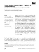
</div><span class="text_page_counter">Trang 18</span><div class="page_container" data-page="18">Traditional cleaning technologies (manual cleaning) no longer meet the new requirements, such as cleaning equipment with complex structures, many small nooks and crannies, which can scratch the pestle. machinery and equipment due to unwanted mechanical impacts. Therefore, the ultrasonic cleaner was born to overcome the above disadvantages.
<i>Figure 1. 1. Industrial Ultrasonic Washing Machine </i>
<b>1.2. Target </b>
Using the Arduino Uno microcontroller to control the power circuit system, calculate the appropriate power for the rusted object to be cleaned.
<b>1.3. Research content </b>
Survey of ultrasonic cleaners available on the market.
Summary of theory about ultrasonic washing machines, components related to washing machines.
</div><span class="text_page_counter">Trang 19</span><div class="page_container" data-page="19">2 Choose a power circuit and pulse generator design option that is consistent with your abilities and theoretical knowledge learned.
Select the frequency appropriate to design needs and the impact of frequency on cleaning ability.
<b>1.4. Limitation </b>
Research and manufacturing washing machine capacity of 36 liters, using ultrasonic wave generator with frequency 40kHz , power of 240 Watt.
Control the blocks using Arduino Uno microcontroller.
The control system allows the user to control and monitor the working system on webserver.
<b>1.5. Research Topics And Range 1.5.1. Research Topics </b>
Examining the various kinds of rusted materials that are appropriate and can effectively enhance the cleaning power of the machine.
Sstudying the composition, principles of operation, and synthesis of theories related to cleaning machines that employ ultrasonic waves.
Designing a power circuit that is in line with the machine's capabilities and the theoretical knowledge that has been acquired.
Selecting a frequency that fits the design specifications and comprehending how frequency affects cleaning efficacy.
Information gathered from scientific research conducted both domestically and internationally, examining previously published works in various scientific journals and references from documents, articles, and textbooks.
<b>1.5.3. Research Methods </b>
Researching methods from experiment and practice.
Gathering information from books, scholarly publications, journals, and documents online.
</div><span class="text_page_counter">Trang 20</span><div class="page_container" data-page="20">3 Conducting surveys, interviews, observations, and secondary data analysis.
<b>1.5.4. Outline Of The Graduation Thesis </b>
Chapter 1: Overview
Chapter 2: Theoretical Basis
Chapter 3: Design Of Mechanical System
Chapter 4: Design Of Electrical And Control System
Chapter 5: Building A User Interface And Interactive Web Interface Chapter 6: Implementation, Experiment Results/ Findings And Analysis Chapter 7: Conclusion And Recommendations
</div><span class="text_page_counter">Trang 21</span><div class="page_container" data-page="21">4
<b>CHAPTER 2. THEORETICAL BASIS </b>
<b>2.1. Ultrasonic Wave Theory Overview </b>
Ultrasound waves are also a mechanical wave and have basic properties through parameters such as frequency, wavelength...
<b>2.2. The Nature Of Sound Waves </b>
Elastic media (gas, liquid or solid) can be considered as continuous media consisting of closely interconnected particles. Normally, each element has a stable equilibrium position.
<i>Figure 2. 1. Types Of Balance </i>
If a force is applied to a certain element A inside this environment, it will leave its stable equilibrium position. Due to the interaction created by the connections with neighboring elements, on the one hand the element is pulled to the equilibrium position, on the other hand it is also affected by the impact force so the element will move back and forth around equilibrium position, which means that the element performs movement in the form of vibrations. This phenomenon continues to occur with other elements of the environment. Mechanical oscillations that are repetitive in nature and propagate in an elastic medium are called elastic waves or mechanical waves. In other words, a wave is a physical phenomenon in which energy is transmitted under the vibrational pattern of material elements of the wave medium.
<b>2.3. Ultrasonic Wave Properties </b>
Sound waves are vibrations of particles of solids, liquids and gases, which are elastic substances. In other words, sound waves are elastic waves propagating in an elastic medium,
</div><span class="text_page_counter">Trang 22</span><div class="page_container" data-page="22">5 which means that all elastic objects can propagate sound waves. Depending on the frequency range, elastic waves are divided into the following regions:
The infrasonic region has a frequency from 1Hz to 20Hz The acoustic region has a frequency from 20Hz to 20kHz
The ultrasonic region has a frequency from 20kHz to 100MHz The ultrasonic region has a frequency > 100MHz
Although it has the same nature as an elastic wave, Due to different frequencies, they have different ap
Characteristics:
Ultrasonic waves carry greater energy than sound waves (for example, with the same amplitude of vibration, the wave energy at a frequency of 1MHz is 10<small>6</small> times greater than the wave energy at a frequency of 1kHz).
In the same wave transmission environment , ultrasonic waves have a short wavelength so they are highly directional, the wave energy travels in a certain direction. Taking advantage of this property, one can create focusing systems to concentrate large amounts of energy over a large area, narrow area.
In the ultrasonic wave range under certain conditions, wave cavitation occurs in liquids. This property is widely used in industry and civil use.
Doppler effect
<b>2.4. Ultrasound Wave Parameters </b>
The following diagram is a representation of a wave, which is a set of compression and expansion that vary in a sinusoidal order, with the peak representing the highest pressure and the bottom representing the lowest pressure.
</div><span class="text_page_counter">Trang 23</span><div class="page_container" data-page="23">6
<i>Figure 2. 2. Waveform Representation </i>
<i>Figure 2. 3. Compression And Rarefaction In A Longitudinal Wave </i>
Characteristic quantities of waves include:
The period T=(s) is the time during which the wave performs one compression and one expansion.
Frequency f=(Hz) is the number of cycles performed in 1 second.
The propagation speed of a sound wave is the distance the sound wave travels after a unit of time.
Wavelength 𝜆(µ𝑚): is the distance the wave travels after a period of time equal to 1 cycle (𝜆 =𝑣. 𝑇 = 𝑣/𝑓).
In the figure, we see that wavelength is the distance between two adjacent peaks or troughs.
</div><span class="text_page_counter">Trang 24</span><div class="page_container" data-page="24">7
<b>2.4.1. Frequency </b>
The frequency of a mechanical wave is also the oscillation frequency of the atoms of the medium in which the wave propagates. Frequency represents the number of cycles per second. The symbol for frequency is f, the unit is Hertz (Hz).
<b>2.4.2. Wavelength </b>
Wavelength 𝜆 is the distance a wave travels in a period of time T. Atoms separated by a distance will have the same vibrational state, that is, they will oscillate in the same phase when the wave passes through the medium.
<b>2.4.3. Velocity </b>
The rate at which energy is transferred between two points in the medium by the motion of the wave is called the wave velocity v.
<b>2.4.4. Absorption Of Ultrasonic Waves By The Transmitting Medium </b>
During the process of wave propagation in the medium, the wave intensity is gradually attenuated due to absorption by the medium and scattering of the wave. Energy loss depends on factors:
- Thermal conductivity, friction coefficient, heterogeneity of the environment. - Frequency of the wave.
<b>2.5. Cleaning Technology </b>
<b>2.5.1. Traditional Cleaning Technology </b>
Cleaning is a problem that we all regularly face every day. In a more general sense, it is the cleaning of unnecessary and troublesome materials from the locations of equipment and parts that need cleaning.
Cleaning can be done in many ways. One of the most common traditional manual methods is to soak the device in a solution. This method is a combination of chemical action and mechanical action. The traditional method is mainly to use a brush to clean parts with simple structures, used for flat, smooth surfaces, not in nooks and crannies or places that are difficult to brush directly.
<i>Advantages: </i>
• The washing process is quick, simple, and does not require high technology. • Cheap
<i>Disadvantages: </i>
</div><span class="text_page_counter">Trang 25</span><div class="page_container" data-page="25">8 • Cannot wash devices with complex structures, narrow gaps, and small nooks and crannies inside the device.
• Causes scratches on the surface by using a brush or broom.
• Deformation of surface and structure causing breakage of small, thin parts of the device.
<b>2.5.2. Using Ultrasonic Cleaning Technology For Cleaning </b>
Nowadays, industrial production is becoming more and more modern, production lines are being created to ensure the production of millions of products of the same type in a year. This reality requires very high quality, size uniformity, and repeatability to ensure easy assembly, less time and effort, and lower product costs. To achieve that, technological lines are often equipped with many ultrasonic cleaning devices in different stages. Make sure to "absolutely" clean the surface of the product before moving on to another processing step on that product. Ultrasonic cleaning technology is especially needed in the manufacturing industry of electronic circuit boards with high component density, in equipment for manufacturing metal mechanical parts with nooks and crannies in shape, many holes but , must have high cleanliness, hardness, and accuracy. Ultrasonic cleaning technology helps us handle dirt on the surface of the above details before entering the coating and surface polishing process.
<b>2.5.3. Ultrasonic Cleaning Technology Cleaning Principle </b>
Ultrasound waves are waves with frequencies greater than 18kHz, at this frequency humans cannot hear it.
In ultrasonic cleaners, the wave frequency is usually in the range of 20kHz - 200kHz. Ultrasonic waves used in ultrasonic washing machines applied to production lines and cleaning of medical instruments have high frequencies from 10kHz - 50kHz. Ultrasonic cleaners using frequencies higher than 50kHz are used to wash optical instruments, biological and industrial filters, and dental cleaning machines in hospitals.
Ultrasonic waves in ultrasonic cleaners are mechanical waves and they have full physical properties such as transmission method, reflection, wave interference, etc., in different transmission environments.
When a mechanical wave is created in air or in a liquid, under the effect of pressure, a quantity of matter is compressed to form waves, this wave is moved towards the lower pressure side and propagates. transmitted in different directions, but the strongest is still the direct direction of the thrust. This wave beam contains countless higher frequency beams, so countless small beams often called bubbles appear in the beam. The size of these bubbles develops quite diversely, usually depending on the frequency of the ultrasound wave. The higher the ultrasound wave, the smaller the bubble size.
</div><span class="text_page_counter">Trang 26</span><div class="page_container" data-page="26">9 These bubbles move one after another in the liquid medium until they hit the surface of an obstacle in the wave path. Under the compression force of the waves, the bubbles burst, creating explosions, shooting liquid particles directly into the surface of the object. These bombardments separate the layers of dirt and dust covering the surface of the liquid and pull them away from the object when negative pressure appears in the liquid near the surface of the object.
<b>2.5.4. Cleaning Process Using Ultrasonic Cleaning Technology </b>
When power is applied to the ultrasonic sensor, this sensor creates mechanical vibrations on its surface with a frequency greater than 20,000 vibrations/second. This mechanical wave is transmitted directly into the stainless steel of the ultrasonic cleaning tank and creates high-frequency shocks in the liquid of the ultrasonic cleaning tank. Under the impact of high-frequency mechanical shocks, countless small-sized bubbles are created in a short time and propagate in all directions within the liquid, and this movement fully complies with the laws of waves. muscle in dragon fluid. The bubbles move forward and hit the surface of the object to be washed, creating a mechanical bombardment of dirt on the surface. Under the impact of this bombardment force, the dust is separated from the surface and easily dissolves into the cleaning solvent thanks to the effect of chemicals. Thus, the smaller the foam, the greater its ability to penetrate, thus having the effect of cleaning the surface of objects with holes or complex zigzag structures, which cannot be achieved with conventional washing technology. The following pictures describe the process of cleaning the surface of an object:
<i>Figure 2. 4. Cleaning Process 1 </i>
</div><span class="text_page_counter">Trang 27</span><div class="page_container" data-page="27">10 The cleaning process is involved in the creation of contact between chemicals and dirt in order for the cleaning solution to dissolve the dirt particles. This requires that the solution come into direct touch with the dust particles.
In order to accelerate the cleaning process, it is necessary to add new cleaning chemicals on a regular basis (see picture below). When chemicals dissolve dirt, a layer of chemicals near the surface of the object is gradually saturated, so its dissolving effect becomes increasingly thick, so the cleaning process is slowed down or completely lost.
<i>Figure 2. 5. Cleaning Process 2 </i>
Ultrasonic waves boost cleaning effectiveness by preventing the creation of a saturated layer of chemicals and allowing the active layer of chemicals to come into direct contact with the surface to be cleaned. They do this by creating and striking the surface with bubble waves.
<i>Figure 2. 6. Cleaning Process 3 </i>
</div><span class="text_page_counter">Trang 28</span><div class="page_container" data-page="28">11 Certain dirt particles are not dissolved; instead, they are loosely adhered to the object's surface by cohesive forces or ion bonding; these particles are easily removed by pushing against the dirt with a force stronger than the dirt's adhesion force to the surface (see figure below).
<i>Figure 2. 7. Cleaning Process 4 </i>
The cleaning solution must moisten the filth particles to be cleaned in order to achieve high ultrasonic cleaning efficiency.
<i>Figure 2. 8. Cleaning Process 5 </i>
</div><span class="text_page_counter">Trang 29</span><div class="page_container" data-page="29">12 Since different kinds of dirt actually dissolve differently in cleaning solutions, choosing the right cleaning agent, supplying the required ultrasonic energy, and taking temperature into account—which is also critical for accelerating the cleaning process—are all necessary to guarantee the efficacy of ultrasonic cleaning technology.
<b>2.5.5. Advantages Of Ultrasonic Cleaning Technology </b>
Unlike other cleaning techniques, the use of bubbles that may reach varying depths and angles allows ultrasonic waves to efficiently clean the surfaces of objects in any shape.
<i>Advantages: </i>
• Consistent and thorough cleaning. The uniform cleaning effect of ultrasonic waves applies to objects of all sizes and complexities, whether it is a single part or multiple parts being cleaned in one go. Ultrasonic technology enables meticulous cleaning of dirt on the entire surface and is not dependent on the operator.
• Safety and environmental compliance by reducing the concentration of hazardous chemicals or replacing corrosive cleaning methods.
• Energy-efficient, labor-saving, and cost-effective.
• Minimizes direct contact between the operator and potentially dangerous cleaning products. • Ultrasonic cleaning devices offer true productivity benefit for specific cleaning applications.
<b>2.6. Factors Influencing The Ultrasonic Cleaning Technology's Cleaning Procedure. 2.6.1. Frequency And Bubble Size Relationship </b>
The figure below illustrates the size of bubble foam in relation to frequency. Higher frequency produces smaller bubbles than lower frequency. Smaller bubbles can be formed in a smaller distance than larger bubbles.
</div><span class="text_page_counter">Trang 30</span><div class="page_container" data-page="30">13
<i>Figure 2. 9. Frequency And Bubble Size Relationship </i>
</div><span class="text_page_counter">Trang 31</span><div class="page_container" data-page="31">14 The bigger the bubble foam, the more intense the cavitation that results from the bubble implosion in water; larger bubble foam is usually produced by high-intensity cavitation; since the bubble size is inversely proportional to the ultrasonic frequency, larger bubble foam is usually produced by lower frequencies; the frequency increases with the number of bubbles; and since the bubble size is inversely related to the ultrasonic power input, lower frequency bubbles are more likely to undergo intense implosion than higher frequency bubbles.
<b>2.6.2. Chemical Effects </b>
A number of chemical cleaning agents are specifically formulated for ultrasonic cleaning, making this technology convenient to use. The table below lists some common chemicals used in ultrasonic cleaning technique. Choosing the appropriate chemical compounds is crucial to the overall success of the ultrasonic cleaning technique. These chemical components need to be compatible with the composition of the metal being cleaned and possess effective cleaning capabilities as well as the ability to generate strong bubble agitation.
</div><span class="text_page_counter">Trang 32</span><div class="page_container" data-page="32">15
<i>Table 2. 1. Several typical metal cleaning solutions. </i>
<b>Cleaning Solution </b>
<b>Composition(g/L) (%) </b>
<b>Temperature </b>
<b>ºC <sup>Metal to Clean Application </sup></b>
Na3PO4 NaCl
30 g/l 5-25 g/l
dirty parts Liquid glass
Na3PO4
20 g/l
Cleaning dirty parts Liquid glass
20 g/l
dirty parts Na3PO4
Na2 C03
5 g/l
Copper, Aluminum,
Zinc
Cleaning dirty parts
HNO3 H2 SO4
H2O
40% 10% 50%
scales and rust H2SO4
HNO3 HCl H2O
4% 9% 13% 74%
50ºC
Steelalloy, Chromium,
Nickel, Modiplen
Cleaning heavily soiled parts
NaOH NaF
100 g/l
Polishing aluminum
surfaces
Choosing the right chemical compound is especially important for the overall success of the ultrasonic cleaning process. This choice of chemical composition must be compatible with the metal base being washed and be capable of removing dirt. It must also have the ability to
</div><span class="text_page_counter">Trang 33</span><div class="page_container" data-page="33">16 create good bubbles. Most chemical cleaners can be used conveniently with ultrasonic technology. They have special formulas for use in ultrasonic cleaning techniques.
<b>2.6.3. Effect Of Temperature </b>
Temperature is considered the most important parameter in creating maximum bubble intensity. Temperature changes lead to changes in viscosity, solubility of gas in liquid, degree of diffusion of gas in liquid, and vapor pressure. In pure water, the level of bubble formation reaches a maximum at temperatures near 160°F (~ 71 °C). The viscosity of the liquid greatly reduces the intensity of bubble formation. Most liquids have viscosity that decreases as temperature increases. To effectively create bubbles, the liquid must contain some small amount of dissolved gas. Gas dissolved in the liquid will be dissolved in the process of creating fertilizer and it can prevent forced bubble collapse. In fact, as the temperature increases, the amount of gas dissolved in the liquid decreases. Diffusion of dissolved gases increases as temperature increases.
When the temperature in the liquid increases too high, causing the liquid to approach the evaporation process, the process of creating steam bubbles is very likely to occur. As the bubbles filled with steam increased, the intensity of the bubbles decreased and some parts of the tank began to evaporate.
<i>Temperature effect: </i>
• The best ultrasonic performance is about 65% of the boiling point of the liquid in use. • Temperatures above 65% of the boiling point will reduce the scrubbing force of the system. • Most ultrasonic cleaners use temperatures between 54 and 82°C.
• When using acidic materials, use the lowest possible temperature to reduce damage to the ultrasonic cleaning tank surface.
<i>Suitable temperature for objects needing cleaning: </i>
• Most industrial parts are best cleaned at 50-70 °C, especially when cleaning microscope parts.
• Electrical and electronic components are best cleaned at 45-55°C.
• Gas-affected items may require cleaning at the highest temperatures up to 80°C.
• For items made from soft, chemically bonded materials, only need to be cleaned at room temperature.
• Laboratory instruments and medical instruments have their own characteristics and should be cleaned ultrasonically at a temperature of 55-65°C.
</div><span class="text_page_counter">Trang 34</span><div class="page_container" data-page="34">17
<b>2.6.4. Time Required For Cleaning </b>
This is determined by temperature conditions, soil type, concentration of cleaning chemicals, shock frequency... It takes time for the cleaning process to take place.
In one tub, it can take five to 15 minutes; in a high-pressure sprayer of a quality cleaner, it may take a few seconds.
<b>2.6.5. Power And Tank Volume Of Ultrasonic </b>
Manufacturers of equipment use different terms to describe ultrasonic power (watt/gallon, watt/liter). Ultrasonic power is defined as the energy transferred to the transducer and is measured in watts per gallon (or liter) of cleaning solution; most cleaning agents require 30-100 watts per gallon (3.78 liters).
The number of bubbles and cleaning effectiveness increase with ultrasonic power, but only up to a certain point; exceeding that point wastes energy and runs the risk of damaging the cleaned components.
Total power is another definition; it is the energy needed to run the entire ultrasonic tank, including the ultrasonic generator and the heating system (if applicable). It should not be confused with ultrasonic power alone.
Peak power, which might be 2, 4, or 8 times greater than average power, is the ultrasonic power produced at the peak of the sound wave.
<b>2.6.6. Considerations When Use A Cleaning Solution And Ultrasonic Cleaning </b>
Selecting the ultrasonic frequency: Most cleaning tanks work at 38–45 kHz, which is sufficient for most cleaning tasks. Lower frequencies produce larger cavitation bubbles, which release more energy when they implode, making them more effective for cleaning; however, lower frequencies tend to be more efficient for rough cleaning processes, though they also increase operating noise. High-value materials, like jewelry, electronics, or the smooth surfaces of lightweight metals, may require a very high frequency of 130 kHz.
Selecting ultrasonic power: The ultrasonic power should rise in proportion to the volume of the cleaning solution. More power typically means faster and more thorough cleaning, but too much power can potentially harm electronic components and material surfaces, particularly metals like aluminum. The ideal power level is one that strikes a balance between thorough cleaning and protecting the objects being cleaned.
Selecting the right cleaning solution: In real life, different kinds of dirt will either dissolve or stay insoluble in cleaning solutions. In order to guarantee that ultrasonic cleaning works, it is important to choose a cleaning agent that is appropriate for the kind of dirt that is there.
</div><span class="text_page_counter">Trang 35</span><div class="page_container" data-page="35">18
<b>2.7. Functions And Categorization Of Transducers: </b>
A device known as an ultrasonic transducer is one that can directly convert electrical energy at an ultrasonic frequency into mechanical oscillations at the same frequency. On the other hand, it can also convert mechanical oscillations into corresponding electrical oscillations. Receiving transducers and transmitting transducers are the two types of transducers that are based on these two functions.
<b>2.7.1. Transmitting Transducer </b>
After being processed and amplified to the necessary level, an electrical oscillation at ultrasonic frequency is sent to the transmitting transducer, which transforms it into a mechanical oscillation that propagates in the medium to accomplish a particular purpose. Transducers can be either electrostrictive or magnetostrictive, depending on the material used in their construction.
Electrostrictive transducers are usually low power and operate at high frequency ranges, whereas magnetostrictive transducers are typically used in high-power devices and operate at low frequencies.
<b>2.7.3. Piezoelectric Transducer </b>
Based on Curie's 1880 discovery of the piezoelectric effect, piezoelectric transducers produce alternating electric charges by means of mechanical vibrations in materials such as quartz crystals and barium titanate, which are typically unstable and have low mechanical load-bearing capacities. American scientists have been producing piezoelectric sensors with high power, durability, and stable frequency response in mechanical and unique environmental conditions since the 1940s.
The deformation effect in piezoelectric materials, on the other hand, is frequently much smaller than in magnetostrictive transducers. The oscillation amplitude of piezoelectric materials typically ranges from 0.1µm to 7µm. Despite this, piezoelectric transducers can operate at frequencies up to 5MHz.
In terms of power, magnetostrictive sensors have a significantly higher power than in piezoelectric sensors. Piezoelectric sensors can convert between reciprocating energy forms,
</div><span class="text_page_counter">Trang 36</span><div class="page_container" data-page="36">19 such as electrical, mechanical, and acoustic energies. Because of their compact size, piezoelectric transducers are well-suited for the production of ultrasonic cleaning machines.
<b>Direct Piezoelectric Effect </b>
In the instance of the direct piezoelectric effect, force applied to the material results in opposite charges being generated on both surfaces; this can be observed by attaching electrodes to the surfaces of a quartz plate coated in silver and measuring the deflection of an electrometer needle. The piezoelectric effect happens when a force is applied to a piezoelectric material, causing it to deform and generate an electrical signal.
The electrometer's needle deflects to the left (figure a) when a tensile force is applied, causing the thin plate to expand; on the other hand, when a compressive force is applied, causing the thin plate to contract; on the other hand, the needle deflects to the right (figure b), indicating a change in the direction of the charges on the two surfaces of the plate.
<i>Figure 2. 10. Direct Piezoelectric Effect (A) Tension Force (B) Compressive Force </i>
This phenomenon illustrates the direct piezoelectric effect, which is the fundamental principle behind the use of piezoelectric materials in a wide range of applications, including actuators, sensors, and ultrasonic devices. It occurs when mechanical deformation results in the generation of opposite charges on the surfaces of a piezoelectric material.
The following equation establishes the link between the charge Q and the force F:
</div><span class="text_page_counter">Trang 37</span><div class="page_container" data-page="37">20 With:
Q is the charge in Coulombs
K is the piezoelectric constant: 6.9 × 10^−8
F is the magnitude of the applied force in kilograms
This equation shows us that when a mechanical force acts on a thin plate's surface, causing mechanical oscillations, an alternating electrical signal with the same frequency as the mechanical oscillation will appear on the thin plate's two electrodes.
Materials that exhibit these properties are referred to as piezoelectric materials, and piezoelectric sensors for ultrasonic wave detection are built on this principle.
<b>Inverse Piezoelectric Effect </b>
This phenomenon, known as the inverse piezoelectric effect, where the mechanical deformation of the material is induced by the applied electric field, illustrates how piezoelectric materials can convert electrical energy into mechanical strain. When two electrodes of a piezoelectric plate are connected to a DC power source as shown in Figure..., it is observed that the thickness of the piezoelectric plate expands. On the other hand, when the polarity of the power source is reversed, the thickness of the piezoelectric plate contracts. The following equation establishes the relationship between L and the applied voltage V:
</div><span class="text_page_counter">Trang 38</span><div class="page_container" data-page="38">21
<i>Figure 2. 11. Inverse Piezoelectric Effect </i>
The relationship states that when a piezoelectric plate is subjected to an alternating electrical signal at frequency f, the thin plate's thickness changes continuously at the same frequency, resulting in the generation of a mechanical oscillation in the surrounding environment.
This idea serves as the foundation for the construction of ultrasonic transducers. Experiments have shown that the oscillation amplitude is maximized when the voltage source V's oscillation frequency and the piezoelectric plate's natural oscillation frequency, which is determined by the material and thickness of the plate and can be expressed by the following equation:
l is the thickness of the piezoelectric plate (mm)
<b>An Ultrasonic Transducer's Composition And Form: </b>
</div><span class="text_page_counter">Trang 39</span><div class="page_container" data-page="39">This indicates that when an alternating current signal with a frequency of f is applied to the coil, the length of the magnetic core will continuously vary with the same frequency, resulting in the creation of a mechanical oscillation in the surrounding environment.
This is the principle behind the construction of magnetostrictive ultrasonic transducers. The length of the magnetic core expands when the two ends of the coil are connected to a DC power source as shown in the figure.
On the other hand, when the direction of the power supply is reversed, the length of the magnetic core contracts.
<b>2.8. Survey The Types Of Ultrasonic Cleaners Available On The Market </b>
Rama Ultrasonic Cleaner
(Rama Ultrasonic Cleaner) is a surface cleaning device using ultrasonic wave technology, used for cleaning grease on motorbike engines, grease-stained machinery, washing dust and rust. Clay sticks to metal, washes glass, washes jewelry, watches, printer heads, washes CNC products & many other applications.
</div><span class="text_page_counter">Trang 40</span><div class="page_container" data-page="40">23
<i>Figure 2. 13. Rama Ultrasonic Cleaner </i>
<b>Specifications: </b>
- Standard capacity: 0.8L - Voltage: 220V-50Hz - Power: 60W
- Frequency: 40KhZ - Number of transducer: 1 - Timer: 0 - 30 minutes - Sink size: 150x85x65 mm
- Machine size: 175x110x125 mm - Weight: 1.6Kg
Jeken Ultrasonic Cleaner
Highly efficient and high-capacity ultrasonic generator used in industry for great cleaning performance, visible to the naked eye.
Complete structure (tank tank, shell, lid, basket ) from high quality SUS 304 stainless steel. Separate independent ultrasonic generator with adjustable ultrasonic power.
</div>