studying the principles of burr formation in hybrid machining process and proposing control options using numerical simulation
Bạn đang xem bản rút gọn của tài liệu. Xem và tải ngay bản đầy đủ của tài liệu tại đây (5.43 MB, 76 trang )
<span class="text_page_counter">Trang 1</span><div class="page_container" data-page="1">
MINISTRY OF EDUCATION AND TRAINING
<b>HO CHI MINH CITY UNIVERSITY OF TECHNOLOGY AND EDUCATION FACULTY FOR HIGH QUALITY TRAINING </b>
<b> </b>
<b>STUDYING THE PRINCIPLES OF BURR FORMATION IN HYBRID MACHINING PROCESS AND PROPOSING CONTROL OPTIONS USING NUMERICAL SIMULATION </b>
<b>LECTURER: PHA HUY TUANSTUDENT: VO DUY TRUNG</b>
</div><span class="text_page_counter">Trang 2</span><div class="page_container" data-page="2"><b>HO CHI MINH CITY UNIVERCITY OF TECHNOLOGY AND EDUCATION FACULTY FOR HIGH QUALITY TRAINING </b>
<b>GRADUATION PROJECT </b>
<b>STUDYING THE PRINCIPLES OF BURR FORMATION IN HYBRID </b>
<b>Advisor : Assoc. Prof. Dr. Pham Huy Tuan </b>
<b>Student’s ID : 19143078 </b>
Ho Chi Minh City, March 2024
<b>MACHINING PROCESS AND PROPOSING CONTROL OPTIONS USING NUMERICAL SIMULATION </b>
</div><span class="text_page_counter">Trang 3</span><div class="page_container" data-page="3"><b>KHOA CƠ KHÍ CHẾ TẠO MÁY CỘNG HÒA XÃ HỘI CHỦ NGHĨA VIỆT NAM </b>
<b>BỘ MÔN THIẾT KẾ MÁY <sup>Độc lập - Tự do - Hạnh phúc </sup>****** </b>
Tp. Hồ Chí Minh, ngày 14 .tháng 3 năm 2024
<b>NHIỆM VỤ ĐỒ ÁN TỐT NGHIỆP </b>
Giảng viên hướng dẫn: PGS. TS. Phạm Huy Tuân ĐT:………..
1. Tên đề tài: Nghiên cứu nguyên lý hình thành bavia trong gia công kết hợp và đề xuất phương án kiểm sốt sử dụng mơ phỏng số
2. Các số liệu, tài liệu ban đầu:
- Các báo cáo liên quan đến mô phỏng gia công, số liệu về chế độ cắt, chế độ rung trong phương pháp gia công kết hợp.
- Thông số vật liệu nhơm Al6061. - Mơ hình khoan có hỗ trợ dao động. 3. Nội dung thực hiện đề tài:
- Tìm hiểu tổng quan về cơng nghệ gia công kết hợp, gia công lai và các ưu điểm của nhóm cơng nghệ này;
- Nghiên cứu ứng dụng các cơng cụ mơ phỏng số để dự đốn q trình hình thành bavia sau gia cơng
- Nghiên cứu ảnh hưởng của rung động tích hợp vào dụng cụ cắt theo một số chỉ tiêu như: giảm thiểu sự hình thành bavia
- Gia cơng, kiểm nghiệm thực tế (nếu đủ thời gian). 4. Sản phẩm: Báo cáo phân tích kết quả mơ phỏng số.
TRƯỞNG NGÀNH
<i>(Ký & và ghi rõ họ, tên) </i>
GIẢNG VIÊN HƯỚNG DẪN
<i>(Ký & và ghi rõ họ, tên) </i>
</div><span class="text_page_counter">Trang 4</span><div class="page_container" data-page="4">TRƯỜNG ĐẠI HỌC SƯ PHẠM KỸ THUẬT TP. HCM
<b>CỘNG HOÀ XÃ HỘI CHỦ NGHĨA VIỆT NAM </b>
<i><b>Độc lập - Tự do – Hạnh phúc </b></i>
<b>KHOA CƠ KHÍ CHẾ TẠO MÁY </b>
<b>PHIẾU NHẬN XÉT ĐỒ ÁN TỐT NGHIỆP </b>
<i><b>(Dành cho giảng viên hướng dẫn) </b></i>
Họ và tên sinh viên: Võ Duy Trung MSSV: 19143078 Hội đồng: 8
Tên đề tài: Nghiên cứu nguyên lý hình thành bavia trong gia cơng kết hợp và đề xuất phương án kiểm sốt sử dụng mô phỏng số
Ngành đào tạo: Công nghệ chế tạo máy
Họ và tên GV hướng dẫn: PGS. TS. Phạm Huy Tuân
</div><span class="text_page_counter">Trang 5</span><div class="page_container" data-page="5"><i>(Cơ sở lý luận, tính thực tiễn và khả năng ứng dụng của đồ án, các hướng nghiên cứu có thể tiếp tục phát triển) </i>
...
...
...
...
</div><span class="text_page_counter">Trang 6</span><div class="page_container" data-page="6">1. <i><b>Hình thức và kết cấu ĐATN </b></i> <b>30 </b>
<i>Đúng format với đầy đủ cả hình thức và nội dung của </i>
<i><b>các mục </b></i>
<i><b>10 </b></i>
<i>Khả năng ứng dụng kiến thức toán học, khoa học và kỹ </i>
<i><b>thuật, khoa học xã hội… </b></i>
<i><b>5 </b></i>
<i>Khả năng thiết kế chế tạo một hệ thống, thành phần, hoặc quy trình đáp ứng yêu cầu đưa ra với những ràng buộc thực tế. </i>
<i><b>15 </b></i>
<i>Khả năng sử dụng công cụ kỹ thuật, phần mềm chuyên ngành… </i>
<i><b>5 </b></i>
3. <i><b>Đánh giá về khả năng ứng dụng của đề tài </b></i> <b>10 </b>
4. <i><b>Sản phẩm cụ thể của ĐATN </b></i> <b>10 </b>
</div><span class="text_page_counter">Trang 7</span><div class="page_container" data-page="7">TRƯỜNG ĐẠI HỌC SƯ PHẠM KỸ THUẬT TP. HCM
<b>CỘNG HOÀ XÃ HỘI CHỦ NGHĨA VIỆT NAM </b>
<i><b>Độc lập - Tự do – Hạnh phúc </b></i>
<b>KHOA CƠ KHÍ CHẾ TẠO MÁY </b>
<b>PHIẾU NHẬN XÉT ĐỒ ÁN TỐT NGHIỆP </b>
<i><b>(Dành cho giảng viên phản biện) </b></i>
Họ và tên sinh viên: Võ Duy Trung MSSV: 19143078 Hội đồng: 8 STT: 6
Tên đề tài: Nghiên cứu nguyên lý hình thành bavia trong gia cơng kết hợp và đề xuất phương án kiểm sốt sử dụng mơ phỏng số
Ngành đào tạo: Công nghệ chế tạo máy Họ và tên GV phản biện: TS. Mai Đức Đãi
...
...
...
<i><b>3. Kết quả đạt được: </b></i> ...
...
</div><span class="text_page_counter">Trang 9</span><div class="page_container" data-page="9">1. <i><b>Hình thức và kết cấu ĐATN </b></i> <b>30 </b>
<i>Đúng format với đầy đủ cả hình thức và nội dung của các </i>
<i><b>mục </b></i>
<i><b>10 </b></i>
<i>Khả năng ứng dụng kiến thức toán học, khoa học và kỹ </i>
<i><b>thuật, khoa học xã hội… </b></i>
<i><b>5 </b></i>
<i>Khả năng thiết kế, chế tạo một hệ thống, thành phần, hoặc quy trình đáp ứng yêu cầu đưa ra với những ràng buộc thực tế. </i>
<i><b>15 </b></i>
<i>Khả năng sử dụng công cụ kỹ thuật, phần mềm chuyên ngành… </i>
<i><b>5 </b></i>
3. <i><b>Đánh giá về khả năng ứng dụng của đề tài </b></i> <b>10 </b>
4. <i><b>Sản phẩm cụ thể của ĐATN </b></i> <b>10 </b>
</div><span class="text_page_counter">Trang 10</span><div class="page_container" data-page="10"><b>ACKNOWLEDGEMENTS </b>
First and foremost, we would like to express our gratitude to our mentor Assoc. Prof. Dr. Pham Huy Tuan, for his guidance, valuable advice, and proposing solutions when the problem became difficult and indeed the project would be difficult to complete without his support. Our sincere thanks to our colleagues at the Information Technology Faculty of HCMC University of Technology and Education, Mr. Hoang Ngoc Vinh and Mr. Pham Tuan Hiep, for their helpful in allowing us to use his workstation to test our numerical simulation models. Finally, we would like to thank our parents for their love and encouragement throughout this process.
While implementing the thesis, we couldn't avoid mistakes, although we tried to complete it by referencing documents, listening, and exchanging ideas. Therefore, we are open to receiving the comments of teachers and readers, as their feedback will help us improve our work.
Ho Chi Minh city, March 8<sup>th</sup>, 2024 On behalf of authors
Vo Duy Trung
</div><span class="text_page_counter">Trang 11</span><div class="page_container" data-page="11"><b>ABSTRACT </b>
In modern times, there is an increasing demand for higher precision in industries such as aviation, defense, medical, and biochemical fields. While conventional machining methods can meet these precision requirements, they encounter significant challenges when dealing with difficult or unconventional materials that are not readily documented in mechanical handbooks. Tool wear also has a considerable impact on production costs, and the presence of burrs necessitates costly deburring processes and additional cleaning time. To address these challenges, vibration-assisted machining has emerged as a promising solution in recent decades. By utilizing external energy sources, such as amplitude and frequency, vibration-assisted machining modifies the cutting mechanism, thereby enhancing machining quality, reducing burrs, and minimizing tool wear. The successful implementation of vibration-assisted machining relies on factors such as structural design, vibration transmission, vibration devices, optimization of process parameters, and performance evaluation.
</div><span class="text_page_counter">Trang 12</span><div class="page_container" data-page="12"><b>TABLE OF CONTENTS </b>
<b>ABSTRACT ... xi</b>
<b>TABLE OF CONTENTS ... xii</b>
<b>LIST OF FIGURES. ... xiv</b>
<b>LIST OF TABLE ... xvi</b>
<b>CHAPTER 1. OVERVIEW ... 1</b>
<b>1.1.Introduction ... 1</b>
<b>1.2. Motivations for topic selection. ... 2</b>
<b>1.3. Scopes and Objectives. ... 4</b>
<b>1.4. Structure of thesis. ... 4</b>
<b>2.1. Hybrid machining process ... 5</b>
<b>2.1.1. Introduction to Hybrid machining. ... 6</b>
<b>2.1.2. Introduction to VAM drilling. ... 6</b>
<b>2.2. Burr formation, measuring, and calibration method. ... 7</b>
<b>2.2.1. Factors affect the burr formation. ... 7</b>
<b>2.2.2. Factors affect to the thrust force. ... 8</b>
<b>2.2.3. Calibration method. ... 9</b>
<b>2.3. Influence of factors in burr height. ... 10</b>
<b>2.3.1. Feed rate, F (mm/rev). ... 10</b>
<b>2.4.4. Response variable in experiment... 13</b>
<b>2.4.5. Introduction Taguchi method. ... 13</b>
<b>CHAPTER 3. FINITE ELEMENT METHOD IN DRILLING PROCESS ... 16</b>
<b>3.1.Cutting parameter and cutting force. ... 16</b>
<b>3.1.1.Geometry for drilling and cutting parameter. ... 16</b>
<b>3.1.2.Cutting Force. ... 17</b>
<b>3.2.Kinetics of VAM drilling. ... 19</b>
<b>3.2.1. Axial uncut chip thickness. ... 19</b>
<b>3.2.2. Plowing force model. ... 21</b>
... 22
... 22
<b>3.3. FEM in machining process. ... 22</b>
<b>3.3. Overview of the Explicit Finite Element method. ... 24</b>
</div><span class="text_page_counter">Trang 13</span><div class="page_container" data-page="13"><b>3.4. Influence of factors in simulation result. ... 27</b>
<b>3.4.1. Stable time and step time. ... 27</b>
<b>3.4.2. Mass scaling. ... 28</b>
<b>3.4.3. Mesh size. ... 28</b>
<b>CHAPTER 4. RESULT OF BUR FORMATION IN SIMULATION ... 30</b>
<b>4.1. Design the 3D drilling simulation model. ... 30</b>
<b>4.2.2. Exit burr result. ... 44</b>
<b>4.2.3. Entrance burr height. ... 47</b>
<b>4.2.3. Compare the exit burr in VAD to CD. ... 50</b>
</div><span class="text_page_counter">Trang 14</span><div class="page_container" data-page="14"><b>LIST OF FIGURES. </b>
Figure 1. 1. The drilling hole and burr ... 3
Figure 2. 1. Hybrid machining process ... 5
Figure 2. 2.a. Stress in chip formation, b. Burr formation in drilling process ... 8
Figure 3. 1. Cutting geometry for drilling ... 17
Figure 3. 2. Drilling cutting force ... 18
Figure 3. 3. Drilling model with vibration ... 19
Figure 3. 4. Geometry of drilling ... 20
Figure 3. 5. Geometry of VAM drilling ... 21
Figure 3. 6. Path of tool model ... 22
Figure 3. 7. Increment time in Explicit ... 25
Figure 3. 8. Error in step time larger than stable time ... 28
Figure 3. 9a) Workpiece with element size 0.06 mm and b) Workpiece with element size 0.01 ... 29
Figure 4. 1. a) ISO metric view of drilling model and b) Front view of drilling model ... 31
Figure 4. 2. a) ISO metric view of simulation drilling model and b) Front view of simulation model ... 32
Figure 4. 3. Meshing in drilling model ... 35
Figure 4. 4. Interaction model ... 36
Figure 4. 5. Boundary condition of cutting tool ... 37
Figure 4. 6. Boundary condition of workpiece in COM ... 37
Figure 4. 7. Boundary condition of workpiece in VAD ... 38
Figure 4. 8. Thrust force at S= 1000 rpm, f = 0.06 mm/rev ... 39
Figure 4. 9. Thrust force comparison between simulation and experiment ... 39
Figure 4. 10. Burr height in simulation... 40
Figure 4. 11. Burr height comparison between simulation and experiment ... 40
Figure 4. 12. Period time of drilling ... 42
Figure 4. 13. ImageJ in burr height measurement of CM in condition cutting 4000 rpm, feed rate 0.2 ... 44
Figure 4. 14. Result of burr height in CM at speed 4000rpm, feed rate 0.2 ... 44
</div><span class="text_page_counter">Trang 15</span><div class="page_container" data-page="15">Figure 4. 15.a) Means graph for exit burr height, b) SN ratios graph for exit burr height
... 46
Figure 4. 16.a) Means graph for entrance burr height, b) SN ratios graph for entrance burr height ... 48
Figure 4. 17. Comparison burr formation between VAM and COM ... 50
Figure 4. 18. Exit burr height ... 51
Figure 4. 19. Entrance burr height ... 51
</div><span class="text_page_counter">Trang 16</span><div class="page_container" data-page="16"><b>LIST OF TABLE </b>
Table 2. 1. Factors in simulation ... 13
Table 2. 2. Input and response variable ... 13
Table 2. 3. L9 Orthogonal Table ... 15
Table 3. 1.Some machining researches using finite element method ... 23
Table 4. 1. Physical parameter of AL6061-T6... 34
Table 4. 2. Parameter of the Johnson - Cook constant in Al6061-T6 ... 34
Table 4. 3. Ductile damage of Al6061-T6 by the Johnson-Cook model... 34
Table 4. 4. Validation the simulation thrust force with experiment result ... 39
Table 4. 5.Validation the simulation Burr height with experiment result ... 40
Table 4. 6. Table of cutting parameter ... 41
Table 4. 7. Level of all parameter ... 43
Table 4. 8. L9 orthogonal array ... 43
Table 4. 9.Simulation result for exit burr height and S/N ratio ... 45
Table 4. 10. Factors effect exit burr height ... 46
Table 4. 11.Simulation result for entrance burr height and S/N ratio ... 47
Table 4. 12.Factors effect entrance burr height... 49
</div><span class="text_page_counter">Trang 17</span><div class="page_container" data-page="17"><b>NOMENCLATURE </b>
S The cutting velocity (rpm) F The feed rate (mm/rev) f The frequency (Hz) A The amplitudes (µm ∆𝑡<sub>𝑠𝑡𝑎𝑏𝑙𝑒</sub> The limit stability (s) L<small>e</small> The element size (mm) c<small>d</small> The wave speed of material E Elastic modulus (MPa) μ Friction coefficient
𝜌 Material’s density (g/mm<small>3</small>)
</div><span class="text_page_counter">Trang 18</span><div class="page_container" data-page="18"><b>ABBREVIATION </b>
COM Convention machining VAM Vibration assisted machining VAD Vibration assisted drilling FEM Finite element method
C3D8R Linear hexahedron reduced integration S/N Signal to noise
PZT Piezoelectric actuator
</div><span class="text_page_counter">Trang 19</span><div class="page_container" data-page="19"><b>CHAPTER 1. OVERVIEW 1.1. Introduction </b>
Aluminum alloy 6061 is composed of several elements, including approximately 0.63% silicon, 0.096% copper, 0.091% zinc, 0.466% iron, 0.179% manganese, 0.53% magnesium, 0.028% titanium, 0.028% chromium, with the remaining portion being raw aluminum. Adding silicon enhances the alloy's strength and ability to withstand high temperatures. Copper improves both strength and corrosion resistance. Zinc contributes to better casting properties and acts as a strengthening agent. Iron, present in small amounts, can impact the alloy's mechanical properties. Manganese improves strength and aids in achieving a favorable grain structure during casting. Magnesium plays a significant role in enhancing strength, corrosion resistance, and weldability. Titanium and chromium, in small quantities, contribute to grain refinement and improved resistance against stress corrosion cracking. [1]
Aluminum alloy 6061 is a widely utilized grade of aluminum alloy that finds applications in various industries. Its versatility and availability in different forms, such as plates, tooling plates, bars, and extrusions, make it a popular choice for commercial and industrial projects. The alloy exhibits favorable characteristics, including good strength, corrosion resistance, and weldability, contributing to its widespread use. To obtain the desired surface quality, dimensional accuracy, and tool life in conventional machining of Al6061-T6 alloy, careful selection of cutting parameters is essential. These parameters include cutting speed, feed rate, depth of cut, tool geometry, and lubrication. [2]
Vibration-assisted machining (VAM) is a favored method among researchers for investigating high-quality surface improvements and burr reduction in machining. Although VAM has demonstrated its effectiveness in numerous cases, there are situations where complete burr elimination may not be achieved. To address this, researchers focus on optimizing cutting conditions and utilizing assisted vibration energy during the machining process [3]. By carefully selecting cutting parameters and incorporating vibration energy, these techniques aim to minimize burr formation further and enhance the overall machining outcome. It is possible to use the FEM software to simulate the chip formation, burr formation, and surface quality of the workpiece to predict the effectiveness of machining. In this case, researchers are likely to limit the
</div><span class="text_page_counter">Trang 20</span><div class="page_container" data-page="20">range of input factors instead of experiments in all these. FEM is a tool that is economics in R&D fields and this is developed now and in the future.
For instance, Isbilir [4] utilized Abaqus/Explicit software to simulate the drilling process of Ti6Al4V workpieces. Their study focused on factors such as thrust force, torque, burr size, and workpiece stress. Similarly, İrfan Ucun employed DEFORM 3D software to create a 3D finite element model for simulating the drilling process of Al7075-T6 alloy. The objective of the study was to validate the model by investigating the thickness of burrs and the influence of cutting conditions on their formation. In the field of milling simulation, Li [5] conducted research on optimizing simulation time for milling processes involving aluminum 6061. Their study aimed to improve simulation efficiency while maintaining accurate results. Chen et al. [6] developed an orthogonal model to examine chip formation and cutting forces in VAM simulation. Their study focused on analyzing the impact of VAM on machining processes.
<b>1.2. Motivations for topic selection. </b>
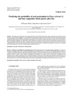
Nowadays, the removal of burrs following machining processes, particularly in drilling operations, has become of utmost importance. However, there are instances or specific positions where eliminating burrs remains challenging. Figure 1.1 provides an academic representation of a specific case that demonstrates the inability to eliminate the formation of an exit burr.
</div><span class="text_page_counter">Trang 21</span><div class="page_container" data-page="21"><i>Figure 1. 1. The drilling hole and burr </i>
The selection of suitable cutting conditions, including speed, feed rate, and depth of cutting, is essential for facilitating the easy removal of burrs using water pressure. Making appropriate choices for these parameters is crucial in ensuring efficient elimination of burrs. Regarding VAM drilling, researchers globally are actively investigating VAM to assess its potential superiority over conventional machining methods.
One approach utilized to determine suitable cutting modes involves conducting experiments using predefined cutting parameters and assessing the effectiveness of VAM in drilling. However, it is crucial to acknowledge that setting up well-equipped technology labs and investing in machining equipment incurs significant costs. Instead of experimental work, Computer-Aided Engineering (CAE) is another way to predict the effectiveness of machining. Designing the machining model is unnecessary, which reduces the funds for experiments. As a result, the author decides to select CAE to predict the behavior of burr in the drilling process rather than experiments.
</div><span class="text_page_counter">Trang 22</span><div class="page_container" data-page="22"><b>1.3. Scopes and Objectives. </b>
This capstone project mainly focuses on analyzing and understanding the mechanisms underlying conventional drilling and vibration drilling models. Because of the resource limitation, the author only examines the outcome trend instead of exacting these. The research can be succinctly summarized as follows:
1. Using the Finite element method – Abaqus software to study the exit burr formation.
2. Find out the trend of exit burr formation in various cutting conditions by Abaqus/Explicit, which recommend the range for experiment works.
3. Compare this to the trend of exit burr formation in convention drilling and VAM drilling.
<b>1.4. Structure of thesis. </b>
<b>Chapter 1: An overview of the thesis, an introduction highlighting the motivation </b>
and reasons for selecting the topic, a description of the experimental methodology, and an outline of the scope and objectives of the thesis.
<b>Chapter 2: Identify the factors studied in the simulation as the response variables, </b>
outcomes, and their levels. It illustrates how to measure the outcomes. Introduction of the Taguchi method in experiments.
<b>Chapter 3. Overview of the Explicit principle in Abaqus, cutting mechanisms. </b>
FEM applied in the drilling machining.
<b>Chapter 4. Report to the exit and entrance burr formation in the drilling process </b>
in convention and VAM. Predict the trend of burr formation.
<b>Chapter 5. Summarize the findings. Present the conclusion, suggest a plan for </b>
addressing the identified issues model, and offer direction for future research.
</div><span class="text_page_counter">Trang 23</span><div class="page_container" data-page="23"><b>CHAPTER 2. BACKGROUND OF THE RESEARCH 2.1. Hybrid machining process </b>
<i>Figure 2. 1. Hybrid machining process </i>
</div><span class="text_page_counter">Trang 24</span><div class="page_container" data-page="24"><b>2.1.1. Introduction to Hybrid machining. </b>
Kapil et al. [7] referred hybrid machining involve combining multiple machining processes to overcome limitations and achieve improved performance. By integrating different methods, hybrid machining addresses challenges such as limited material removal rates, surface quality issues, and the machining of complex workpieces. This approach combines traditional machining processes like milling, turning, or drilling with non-traditional methods such as laser machining or electrochemical machining. Another aspect of hybrid machining involves integrating additive manufacturing with subtractive processes, combining the advantages of both approaches.
Benefits of hybrid machining include increased material removal rates, enhanced surface quality, improved machining flexibility, process optimization, and potential time and cost savings. However, challenges exist in terms of process integration, tooling requirements, and the complexity of optimizing parameters.
Hybrid machining is a rapidly evolving field with ongoing research and development aimed at exploring new process combinations, optimizing parameters, and expanding application possibilities. The goal is to enhance machining capabilities and meet the evolving demands of modern manufacturing industries.
<b>2.1.2. Introduction to VAM drilling. </b>
Brehl [8] defines vibration-assisted machining as a technique that involves applying controlled vibrations during the machining process to improve cutting performance and machining outcomes. It has gained significant attention as a solution to challenges like tool wear, chip control, and surface quality, which concern the effects of vibration-assisted machining on cutting performance, such as reducing cutting forces, improving chip control, enhancing material removal rates, and impacting tool wear and tool life. It would also examine the influence of vibration parameters, such as amplitude, frequency, and direction. Surface quality and dimensional accuracy are important considerations in machining. The review would discuss how vibration-assisted machining affects surface roughness, surface integrity, and dimensional stability. It would highlight the mechanisms by which vibrations help reduce surface defects like built-up edge and chatter marks.
Modeling and optimization techniques used in vibration-assisted machining would be another focus of the review. This would include analytical, numerical, and
</div><span class="text_page_counter">Trang 25</span><div class="page_container" data-page="25">experimental methods employed to understand the process and optimize vibration parameters. Techniques like finite element analysis, analytical modeling, and response surface methodology would be explored.
<b>2.2. Burr formation, measuring, and calibration method. 2.2.1. Factors affect the burr formation. </b>
Saunders [9], in the majority of metal cutting operations, the emergence of burrs is observed as the cutting tool completes its exit from the workpiece. These exit burrs pose a challenge as they require supplementary manufacturing steps to effectively address them, including disassembly and deburring procedures.
The model for burr formation encompasses five distinct elements, namely cutting force modeling, thermal modeling, stress modeling, evaluation of a failure criterion, and simulation of material removal. In this thesis, the thermal factor is skipped.
In order to create a comprehensive model for burr formation, it is essential to have precise the cutting forces exerted during drilling. These cutting forces are responsible for applying loads to the finite element model. Specifically, during drilling, the thrust force is distributed as a directed pressure on the top surface of the material located in front of the drill.
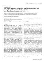
</div><span class="text_page_counter">Trang 26</span><div class="page_container" data-page="26">a
<i>Figure 2. 2.a. Stress in chip formation, b. Burr formation in drilling process </i>
After the drill penetrates the workpiece, the material present in front of the drill sustains the applied thrust force, allowing the cutting process to persist. The cutting operation proceeds until the maximum normal stress at point B (as depicted in Figure 2.2) attains the ultimate stress level of the material. Subsequent to the failure at pointB, the remaining material undergoes deformation and bends over, resulting in the formation of a burr with a height denoted as Rf.
<b>2.2.2. Factors affect to the thrust force. </b>
In the research article “Analysis of the effects of process parameters on exit burrs in drilling using a combined simulation and experimental approach”, Lauderbaugh [10] explored the effect of three factors: feed rate, spindle speed, and geometry cutting tools. In that research, the feed rate is a factor that has the most influence on burr height.
In this thesis, all simulations use the same geometry cutting tool. The feed rate and the spindle speed are variable in conventional drilling. In VAM drilling, two factors amplitude and frequency, are added in.
Point B
</div><span class="text_page_counter">Trang 27</span><div class="page_container" data-page="27"><b>2.2.3. Calibration method. </b>
The thrust force is a critical factor influencing burr formation. In this thesis, it is imperative to conduct simulations to analyze the outcomes of the thrust force. Subsequently, a comparison is made with previous results obtained from other simulations or experimental studies. To ensure accurate results, the material properties and contact parameters are carefully calibrated. Once the calibration process is completed, the cutting condition and geometry cutting tool parameters are systematically varied in order to facilitate new simulations.
Chang [11] used to perform experiment that the simulation and experiment in 6061 VAM drilling. Author determined that the thrust force in VAM is smaller than convention. The thrust force results obtained from the experiments were compared to the corresponding simulation resultsare represented by solid data points, while the experimental data is depicted by hollow circular data points. The maximum deviation observed between the experimental and simulation results was 10%. Notably, a reduction of 16% in the thrust force was achieved when the vibration frequency was set to 10 kHz. This paper presents a thrust force model to predict the thrust force during vibration-assisted drilling of aluminum 6061-T6. The model incorporates plowing force and strain rate-dependent shear strength to provide more accurate predictions than the existing model. The results of 72 drilling experiments with TiN-coated standard twist drills are reported, and the predictions from the developed thrust force model are compared with the experimental results. The comparison demonstrates that the maximum deviation between the predictions and the averaged values of the experimental measurements is only 7% using the proposed model.
Li et al. [12] investigated VAM drilling with the frequency range (100 – 1000Hz) and amplitude (0.003 – 0.0035 mm). They supposed that an elevated vibration frequency has been determined to correlate with a reduction in burr height. When comparing the burr height values between conventional drilling (CD) and the optimized low-frequency vibration-assisted drilling (LFVAD) technique, a substantial decrease ranging from 52.75% to 53.16% was observed.
</div><span class="text_page_counter">Trang 28</span><div class="page_container" data-page="28"><b>2.3. Influence of factors in burr height. 2.3.1. Feed rate, F (mm/rev). </b>
Chen [13] supposed that the feed rate in drilling refers to the speed at which the drill advances into the workpiece. It is a critical factor in the drilling process and has a direct impact on the formation of burrs. Analyzing the relationship between feed rate and burr height is crucial for optimizing drilling operations and achieving the desired surface quality. When the feed rate is increased during drilling, it can lead to an increase in burr height. This is primarily because the higher feed rate results in increased cutting forces, causing the cutting tool to push the material upward and create raised edges around the drilled hole. The magnitude of the burr height increase depends on various factors, such as the material being drilled, drill geometry, cutting conditions, and the stability of the setup. Experimental investigations are conducted to study the influence of feed rate on burr height. These experiments involve testing different materials at varying feed rates, and the resulting burr heights are carefully measured and analyzed. The empirical data obtained from these experiments help to establish the relationship between feed rate and burr height.
<b>2.3.2. Revolution, S (rpm). </b>
Zhang [14] supposed cutting speed, denoting the rotational velocity of the drill bit during micro drilling, plays a crucial role in burr formation. Higher cutting speeds have the propensity to generate more heat and induce material softening, which can lead to the creation of larger burrs. Therefore, conducting an investigation into the effect of cutting speed on burr formation is essential to establish an optimal range that simultaneously minimizes burr size and ensures efficient productivity.
<b>2.3.3. Vibration Frequency, f (Hz). </b>
Liao [15] Vibration-Assisted Machining (VAM) drilling has been shown to enhance drilling performance through the reduction of cutting forces, improved chip evacuation, and enhanced surface quality. A notable advantage of VAM drilling is its ability to effectively decrease burr formation. This is achieved by utilizing the oscillatory motion of the cutting tool to facilitate chip segmentation, thereby preventing the formation of lengthy chips that contribute to burr generation. Consequently, this technique leads to diminished burr height and improved hole quality, particularly in materials prone to burr formation like titanium alloys. Researchers commonly conduct
</div><span class="text_page_counter">Trang 29</span><div class="page_container" data-page="29">experimental studies to explore the impact of different vibration frequencies on drilling performance, surface integrity, and burr formation.
Generally, higher vibration frequencies are inclined to promote chip segmentation, resulting in smaller chip sizes and smoother material flow. This, in turn, aids in minimizing burr formation. However, it is important to note that the optimal frequency range for reducing burr height may vary depending on the specific material and drilling conditions.
Li [16] conducted a series of experiments to analyze the effects of assisted drilling on two main aspects: reducing drilling force and improving hole quality. They investigated how vibration assistance, achieved through oscillatory motion, can effectively decrease drilling forces compared to conventional drilling methods. The study also focused on enhancing hole quality by minimizing burr formation and improving surface finish. The experimental data and analysis presented in the paper demonstrate the positive outcomes of vibration assistance in achieving these goals.
vibration-Additionally, the authors found that the frequency of vibration was the most significant factor influencing burr formation.
<b>2.3.4. Amplitude, A (µm). </b>
Zhang [17] provides valuable insights into optimizing vibration parameters to improve the surface quality of drilled holes in titanium alloy. The study specifically investigates how vibration amplitude affects the surface quality of drilled holes in titanium alloy. Through experiments, the authors varied the vibration amplitude between 10 and 30 um and measured the surface roughness values of the drilled holes. The results indicated that increasing the vibration amplitude resulted in a decrease in surface roughness, indicating an improvement in the surface quality of the drilled holes.
Similarly, other the study examined the impact of different vibration amplitudes, ranging from 5 to 20 um, on the surface quality and burr height in vibration-assisted drilling (VAM). The results demonstrated that increasing the vibration amplitude led to a decrease in surface roughness and waviness values, indicating an improvement in the surface finish of the drilled holes. [18]
</div><span class="text_page_counter">Trang 30</span><div class="page_container" data-page="30"><b>2.4. Experiment planning. 2.4.1. Phenonmenon. </b>
In the field of science, it is essential to conduct practical experiments to gather data and knowledge about an object or process. These experiments help in obtaining accurate information and identifying the most suitable research direction for the problem being studied. Through the process of experimentation, the characteristics of the research object are analyzed and evaluated, resulting in precise and reliable data. Analyzing and processing this data provides researchers with a deeper understanding and knowledge of the object, allowing them to identify its fundamental characteristics and establish relationships between its parameters using mathematical equations and graphs. This comprehensive understanding obtained through mathematical models and graphical representations enables researchers to apply their knowledge to various real-world applications.
Performing practical experiments is crucial as it lays the foundation for all research and development in engineering, especially in the field of optimization. Nowadays, a combination of theoretical research and practical experiments is commonly employed. Theoretical research helps in understanding the underlying principles and processes, while practical experiments validate and supplement the results obtained from theoretical studies, leading to a better understanding of the underlying mechanisms. Experimental planning is a crucial method used to achieve predetermined goals in research. Proper planning ensures that the output obtained is sufficient and accurate, providing clear answers to the research questions and enhancing our understanding of the research object. [19]
<b>2.4.2. Factors in simulation. </b>
The four factors simulation is divided into three levels in Table 2.1.
</div><span class="text_page_counter">Trang 31</span><div class="page_container" data-page="31"><i>Table 2. 1. Factors in simulation </i>
<b>2.4.4. Response variable in experiment. </b>
In this experiment, the output or response variable is factors that affect burr height in the drilling process. These are exit burr height, entrance burr height and thrust force 𝐹<sub>𝑡</sub>. Table 2.3 indicates all factors in experiments.
<i>Table 2. 2. Input and response variable </i>
1 Spindle speed <i>rpm </i> A B C
<b>2.4.5. Introduction Taguchi method. </b>
When planning an experiment, selecting an appropriate experimental design is of utmost importance as it directly affects the experimental process and the resulting outcomes. In the case of qualitative or quantitative experiments involving a single factor, it is relatively straightforward to control the number of experiments based on the objectives and scope of the study. However, for more complex experiments that involve the examination of multiple factors (combinations of qualitative and quantitative factors), determining the necessary number of experiments becomes more challenging. In such cases, a one-factor experimental model is insufficient, and the use of a multifactor model becomes necessary.
</div><span class="text_page_counter">Trang 32</span><div class="page_container" data-page="32">An experimental model aims to identify the optimal values for parameters while considering the factors involved and their respective influences. It also minimizes the number of experiments required. One notable approach to address this challenge is the Taguchi method, which was proposed by Genichi Taguchi, a Japanese statistician and engineer. The Taguchi method utilizes orthogonal arrays, similar to factorial designs, but follows a rigorous process that allows for conducting fewer experiments while obtaining more reliable data.
The fundamental concept behind the Taguchi method is to identify the key technological factors that maximize efficiency by detecting and mitigating the effects of disturbances. These factors, referred to as input variables, impact the results in two directions: one direction brings the results closer to the desired goal, known as the "Signal," while the other direction causes the results to deviate from the target, known as "Noise." The evaluation of the signal-to-noise ratio (S/N) serves as an effective indicator for assessing and selecting parameters. Parameter sets with higher S/N ratios are considered more favorable, while those with lower S/N ratios are considered less desirable. [20]
Based on the type of problem at hand, there are 3 distinct methods available to calculate the signal-to-noise (S/N) ratio. [21]
Higher is better:
𝑁 <sup>= −10𝑙𝑜𝑔</sup><sup>10</sup><sup>∑</sup>1𝑦<sub>𝑖</sub><sup>2</sup>
(2.2)
Average of rate of S/N for each level of every factor:
𝑛<sub>𝑚</sub> = 𝑀𝑒𝑎𝑛 (<sup>𝑆</sup>𝑁<sup>) =</sup>
𝑆𝑁<sup>) 𝑖</sup>
</div><span class="text_page_counter">Trang 33</span><div class="page_container" data-page="33">In this case, it is possible to select orthogonal L9 table with four factors and three levels.
<i>Table 2. 3. L9 Orthogonal Table </i>
No. Speed Feed rate Frequency Amplitude
</div><span class="text_page_counter">Trang 34</span><div class="page_container" data-page="34"><b>CHAPTER 3. FINITE ELEMENT METHOD IN DRILLING PROCESS 3.1. Cutting parameter and cutting force. </b>
<b>3.1.1. Geometry for drilling and cutting parameter. </b>
Drilling is a machining process utilized to generate or expand circular holes in solid materials by means of a rotary drill bit. The drill bit, often featuring multiple cutting points, is brought into contact with the workpiece and rotated at considerable speeds, ranging from hundreds to thousands of revolutions per minute. This rotational motion causes the cutting edge of the drill bit to engage with the workpiece, effectively removing material in the form of chips during the drilling operation. In figure 3.1. shown the cutting geometry for drilling [22].
During the chip removal stage in drilling, the cutting speed relies on the tool's rotary motion. This speed is quantitatively described by an equation that captures the relationship between the rotational movement of the tool and the resulting cutting speed:
𝑣 = <sup>π .d .n</sup>
where d is the diameter of drilling bit, n is the velocity of drill.
The feed (s) in drilling represents the axial distance traveled by the drill during a single cycle. It is typically measured in millimeters per revolution. Drills typically consist of two cutting edges or teeth, and the feed rate can be specified in terms of the number of teeth (z), indicating the amount of feed per tooth:
</div><span class="text_page_counter">Trang 35</span><div class="page_container" data-page="35">where A<small>sz</small> is the cutting face, k<small>s</small> is specific feed force.
The specific feed force (𝑘<sub>𝑠</sub>) is determined by several factors, including the material type, feed velocity, and tool wear. To accurately incorporate these influences, additional correction factors are introduced and combined with the basic specific feed force (𝑘<sub>𝑥</sub>).
<small> </small>
<small> </small>
<small> </small>
</div><span class="text_page_counter">Trang 36</span><div class="page_container" data-page="36"><i>Figure 3. 2. Drilling cutting force </i>
𝑘<sub>𝑠</sub> = 𝑘<sub>𝑥</sub>𝑘<sub>𝑤</sub>𝑘<sub>𝑟</sub>ℎ<sup>−𝑚</sup> (𝑁 𝑚𝑚⁄ <sup>2</sup>) (3.7) The specific feed force directly related to the basic cutting face of the tool (𝑘<sub>𝑥</sub>). The influence of tool wear is quantified by the correction factor (𝑘<sub>𝑤</sub>). The depth of cut is represented by the parameter (h), while the correction factor (m) accounts for the impact of the material type. Additionally, the correction factor (𝑘<sub>𝑟</sub>) encompasses all other relevant influences on the specific feed force.
The factor 𝑘<sub>𝑠</sub> accounts for the impacts of material type, feed velocity, and tool angle (θ) on the drilling process, as illustrated in Figure 3.1. It quantifies the relationship between these factors and the specific characteristics of the cutting face (𝐴<sub>𝑠𝑧</sub>).
where d is the diameter of drill bit. As a result, feed force 𝐹<sub>𝑠𝑧</sub> yields
𝐹<sub>𝑠𝑧</sub> = 𝑘<sub>𝑥</sub>𝑘<sub>𝑤</sub>𝑘<sub>𝑟</sub>𝑑(𝑓<sub>𝑧</sub>𝑠𝑖𝑛𝜃)<sup>1−𝑚</sup> (3.9) where fz ¼ up=n feed per tooth and
The parameter α<small>fv</small> is determined by a function that considers both the feed velocity (u) and the influence of tool wear, which is characterized by the correction factor 𝑘 . Tool wear is primarily caused by the mechanical and thermal stresses
</div><span class="text_page_counter">Trang 37</span><div class="page_container" data-page="37">occurring in the contact area between the cutting edges and the workpiece, resulting from friction during the drilling process.
<b>3.2. Kinetics of VAM drilling. 3.2.1. Axial uncut chip thickness. </b>
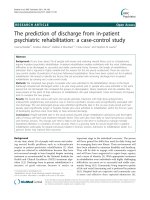
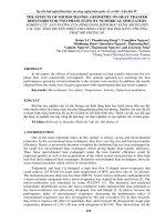
Figure 3.3 show the direction of vibration in drilling. In general, the vibration is applied for workpiece.
<i>Figure 3. 3. Drilling model with vibration </i>
The overall displacement z in figure 3.4 is determined by the sum of two factors: the displacement attributed to the feed (𝐹𝑛𝑡) and the displacement associated with vibration, 𝐴𝑠𝑖𝑛(2𝜋𝑓𝑡) + 𝐹𝑛𝑡:
where A and 𝑓 are the vibration amplitude (mm) and frequency (Hz), respectively; F is the feedrate (mm/rev); n is the spindle speed (rev/sec); and t is the time (s). Similarly, the instantaneous velocity is:
</div><span class="text_page_counter">Trang 38</span><div class="page_container" data-page="38">In order to determine the axial uncut chip thickness, which plays a vital role in the estimation of cutting forces, it is imperative to observe and measure the maximum depth of material removal precisely at the specific rotational location of interest, z<small>max</small>(θ).
Transform the 2πnt to θ, the equation 3.10 will be expressed: 𝑧(𝜃) = 𝐴𝑠𝑖𝑛 (<sup>𝐹𝜃</sup>
𝑛 <sup>) +</sup>𝑓𝜃
(3.13)
z<small>max</small>(θ), the axial position can be determined by observing the location of the cutting lips before the current instance. In the case of a two-flute drill, where the cutting lips are separated by a distance of π radians, the axial positions of all the cutting lips prior to the current moment are equivalent to z(θ-mπ). Where m is a positive integer.
<i>Figure 3. 4. Geometry of drilling </i>
Z
</div>