báo cáo thí nghiệm mạch tuyến tính 1 ee3716
Bạn đang xem bản rút gọn của tài liệu. Xem và tải ngay bản đầy đủ của tài liệu tại đây (1.01 MB, 23 trang )
<span class="text_page_counter">Trang 1</span><div class="page_container" data-page="1">
ĐẠI HỌC BÁCH KHOA HÀ NỘITRƯỜNG ĐIỆN - ĐIỆN TỬ
BÁO CÁO THÍ NGHIỆM
MẠCH TUYẾN TÍNH 1 (EE3716)
Họ tên sinh viên: Hoàng Quang HưngMSSV: 20202749
Lớp: CTTT Kỹ thuật ĐK - TĐH 02 - K65Mã lớp TN: 742959
Hà Nội, tháng 5 năm 2024
</div><span class="text_page_counter">Trang 2</span><div class="page_container" data-page="2">Lab #1: Kirchhoff's Current and Voltage Laws
I. OBJECTIVES
To learn and apply Kirchhoff's Current Law. To learn and apply Kirchhoff's Voltage Law.To obtain further practice in electrical measurements
Compare experimental results with those using hand calculations.
II. BACKGROUND AND THEORY
1. Kirchhoff's Current Law (KCL)Kirchhoff's Current Law (KCL) states that the algebraic sum of currents leaving anynode or the algebraic sum of currents entering any node is zero. KCL can be stated asthe sum of the currents entering a node must equal the sum of the currents leaving anode
Kirchhoff's Current Law can also be expressed as follows:
a) The algebraic sum of the currents entering a junction (node) equals zero. b) The algebraic sum of the currents leaving a junction (node) equals zero.c) The algebraic sum of currents entering a node equal to the algebraic sum of
currents leaving a node.2. Kirchhoff's Voltage Law (KVL)
Kirchhoff's Voltage Law (KVL) states that the algebraic sum of voltages around aclosed path is zero. As you make a summation of voltages, it is suggested that youproceed around the closed path in a clockwise direction. If you encounter a positive(+) sign as you first enter the circuit element, add that value. On the contrary, if youfirst encounter a negative sign as you enter the circuit element, then subtract the valueof that voltage.
We can state Kirchhoff's Voltage Law in three ways which are all equivalent:
The algebraic sum of the voltage drops around any closed path of an electriccircuit equals zero.
</div><span class="text_page_counter">Trang 3</span><div class="page_container" data-page="3">The algebraic sum of the voltage rises around any closed path of an electriccircuit equal to zero.
The algebraic sum of the voltage rises equals the algebraic sum of thevoltage drops around any closed path of an electric circuit.
III. EQUIPMENT AND PARTS LIST
● Digital Multimeter (DMM)● DC power supply - Circuit breadboard● Resistors
IV. PROCEDURE
1. Without substituting in numbers for R1, R2, R3, and R4 apply Kirchhoff's CurrentLaw at nodes 1 and 2 so as to obtain two equations in terms of the two unknown nodevoltages V1 and V2. Simplify these equations.
2. Let R1=100Ω, R2 = 500Ω, R3= 50Ω, and R4= 150Ω in the equations of Step 1.Solve these equations by hand for V1 and V2.
From V1 and V2 find Va, Vb, Vc, Ia, Ib, and lc.
3. Measure the resistors. Use these values to find V1, V2, Va, Vb, Vc, Ia, Ib, and Ic asin Step 2.
4. Construct the circuit shown in the Figure below.
</div><span class="text_page_counter">Trang 4</span><div class="page_container" data-page="4">5. Use the multimeter to measure the indicated three currents and five voltages6. Compare the results of Step 2 with those obtained from the theoretical calculationsof Steps 2 and 3 above.
7. Using the measured values of the three currents, check KCL at node 2
8. Use your measured values of the source voltage, Va. Vb, and Vc to checkKirchhoff's Voltage Law for the outer loop of the circuit.
V. CALCULATIONS AND COMPARISONS
1. Experiment resultsVR 1+R 2+<sub>R</sub><sup>R 3.</sup><sub>3+ 4</sub><sub>R</sub><sup>R</sup><sup>4</sup>
100 500+ +<sup>50.150</sup>50 150+
Ib=<sup>−24+(Va Vb</sup><sup>+</sup> <sup>)</sup>R 3 <sup>=</sup>
−24 +Ia(R 1+R 2)R 3 <sup>=</sup>
−24 +22.59
50 <sup>=−28.20(mA)</sup>Ic Ia Ib= + =9.45(mA)
</div><span class="text_page_counter">Trang 5</span><div class="page_container" data-page="5"><small>Experimental results (mA)Theoretical results (mA)Differences (%)</small>
</div><span class="text_page_counter">Trang 6</span><div class="page_container" data-page="6">Vb=Ia .R 2=37.65 ×10 × 500 18.825= (V )Vc=Ic .R 4=9.45× 10<small>−3</small>
<small>Experimental results (mA)Theoretical results (mA)Differences (%)</small>
=> The difference between experimental and theoretical results is less than 1%, which is acceptable.
VI. CONCLUSIONS
The measured value are reasonably accurate and are roughly the same as the nominalvalues.
</div><span class="text_page_counter">Trang 7</span><div class="page_container" data-page="7">Lab #2: Nodal Analysis
I. OBJECTIVES
- To learn and apply Nodal analysis.
- To obtain further practice in electrical measurements.
- Compare experimental results with those using hand calculations.
II. BACKGROUND AND THEORY
Analysis of electrical networks involves the determination of node voltages and loopor branch currents. Nodal analysis refers to the technique of writing equations wherethe unknown quantities are the node voltages of the circuit. Kirchhoff's current law isused to define the equations at each node in the circuit, using currents obtained byOhm's law.
III. EQUIPMENT AND PARTS LIST
- Digital Multimeter (DMM)- DC power supply- Circuit breadboard- ResistorsIV. PROCEDURE
- Consider the bridge circuit shown in Figure below.
</div><span class="text_page_counter">Trang 8</span><div class="page_container" data-page="8">
- One useful property of the bridge circuit is the so-called balance condition thatoccurs when the relationship among the bridge resistors ("legs") is such that(R1/R2)-(R3/R4). Note that in the balance state the node voltages V2 and V3are equal, meaning that the current RS must be zero. Also note that the balancecondition depends only upon the resistor ratios, not the applied voltage V.- The bridge circuit can be used to determine the value of an unknown resistor if
several known resistors are available. For example, if the R3 leg was anunknown resistor we could use various combinations of known resistors for theR1, R2, and R4 legs until the balance condition was achieved. We would thenknow that R3= R4*(R1/R2).
- Using the resistance and voltages given in the Figure, determine all nodevoltages and branch currents in the circuit. Using the voltage and currentvalues, calculate the power dissipated by each resistor.
- Determine a new value for R4, leaving the other resistors unchanged, that willbalance the bridge circuit. Assume an adjustable resistor is used so that anyresistance value can be obtained.
- Construct the circuit shown in the Figure.
</div><span class="text_page_counter">Trang 9</span><div class="page_container" data-page="9">- Measure and record the resistance of each resistor you use.
- Use the multimeter to adjust the power supply. Measure and record all nodevoltages and branch currents.
V. EXPERIMENTAL RESULTS
1. Nominal valuesV<sub>3</sub>−V<sub>2</sub>R<sub>5</sub> <sup>+</sup>
V<small>3</small>−0R<sub>4</sub> <sup>=</sup>
⟹
{
V<sub>2</sub>=5.56 VV<sub>3</sub>=7.98 VThe branch current:
500 <sup>=12.88(mA)</sup>I<sub>2</sub>=<sup>V</sup><small>2</small>
150 <sup>=37.06 (mA</sup>I<sub>3</sub>=<sup>V</sup><small>1</small>−V<small>3</small>
100 <sup>=40.20(mA)</sup>I<sub>4</sub>=<sup>V</sup><small>3</small>
500 <sup>=15.96(mA )</sup>I<sub>5</sub>=<sup>V</sup><small>3</small>−V<sub>2</sub>
</div><span class="text_page_counter">Trang 10</span><div class="page_container" data-page="10">P<small>3</small>=I<small>3</small>×R<small>3</small>=¿
P<small>4</small>=I<small>4</small>×R<small>4</small>=¿</div><span class="text_page_counter">Trang 11</span><div class="page_container" data-page="11">
Lab #4: Thévenin and Norton Equivalent Circuits
I. OBJECTIVES
- To understand the Thévenin's and Norton equivalent of a circuit.- To check the experimental values versus calculated values.- To find the conditions for maximum power delivered to a load.
- To build a Thévenin equivalent of the original circuit and check to see if itreally is equivalent
II. BACKGROUND & THEORY
1. Thévenin's theoremThévenin's theorem states that any two-terminal circuit with linear elements can berepresented with an equivalent circuit containing a single voltage source in series witha single resistor.
The equivalent circuit consists of an independent voltage source Voc and a seriesresistor R. The resistor Rt is determined by removing all independent sources (shortvoltage sources and open current sources). V is found by measuring the open circuit<small>oc</small>voltage across the output and i is found by measuring the current between the shorted<small>sc</small>output connections.
Voc and R , are computed as follows: V = V<small>ttoc</small>
The load resistance that absorbs the maximum power from a two-terminal circuit isequal to the Thévenin resistance.
The maximum voltage at the output of a linear source is:
</div><span class="text_page_counter">Trang 12</span><div class="page_container" data-page="12">i<small>n</small>The maximum current at the output of a linear source is:
4 R<small>T</small>
4 <sup>=</sup>v<small>oc</small>
III. EQUIPMENT AND PARTS LIST
- Digital Multimeter (DMM)- DC power supply- Circuit breadboard- ResistorIV.PROCEDURE
Experiment 2:1. Construct the circuit below (using a 100 resistor with a large enough power rating toabsorb isc)-
Measure v and is at the output. Remember to measure the resistance of each resistor<small>oc</small>used. Now imagine that you are unable to measure because a 100 resistor with a largeenough power rating is unavailable (or pretend the power supply might be damaged).
Take an additional measurement that will allow you to construct the Theveninequivalent.
</div><span class="text_page_counter">Trang 13</span><div class="page_container" data-page="13">2. Place the following "loads" across the output and record voltage across and currentthrough.
V. EXPERIMENT RESULTS
Vopen = 10.05 (V)Ishort = 26.02 (mA)
Equivalent Thevenin’s resistor: 380.64 (Ω)
When loads are placed:
With this additional measurement data, we can construct the Thevenin equivalentcircuit, which consists of a voltage source (Vth) in series with a resistor (Rth). TheThevenin voltage will be the open-circuit voltage measured earlier, and the Theveninresistance will be calculated based on the load measurements.
</div><span class="text_page_counter">Trang 14</span><div class="page_container" data-page="14">Lab #5: Power Relationship
II. BACKGROUND AND THEORY
An arbitrary connection between a source and a load can be depicted in Fig. 1. Notethat the voltage source and source resistance Rs could actually be the Theveninequivalent circuit for a more complicated network.
Case 1: Maximum voltage transfer
To maximize the load voltage Vload the relationship between Rs and Rload can beexpressed as:
</div><span class="text_page_counter">Trang 15</span><div class="page_container" data-page="15">Case 2: Maximum current transfer
If we need to supply the maximum available current from the source to the load, weneed a different relationship between RL and Rs. Specifically:
Assuming the source resistance is fixed, the load current is maximized for RL << RS
Case 3: Maximum power transfer
To maximize the power delivered to the load, assuming the source resistance is fixed,we need to maximize the power expression with respect to RL
The maximum power transfer occurs for RL=RS. This is in agreement with themaximum power transfer in the Thevenin equivalent lab.
III. EQUIPMENT AND PARTS LIST
Digital multimeter (DMM)DC power supply
Circuit breadboardResistors
IV. PROCEDURE
4.1. Theoretical Calculations</div><span class="text_page_counter">Trang 16</span><div class="page_container" data-page="16">Consider the circuit in Fig. 2. Then use specific resistance values to calculate thepower dissipated in each of the resistors with the optimum load resistor attached. Use aprogram to solve for the branch currents if you wish.
4.2. Laboratory experiment
1. Assemble the circuit in Fig. 2 using the supply for Vsource, R =330Ω, and R<small>SL=1Ω.</small>Use the multimeter to set Vsource to 12V (DC), Measure and record the voltage acrossRL.
2. Now replace the 1Ω load resistors in turn with the nominal resistor values (resistorper value) in your lab kit (10Ω, 100Ω, 200Ω, etc.) and record the load voltage.Remember to record the actual values of the resistors you use 3. Construct the circuitshown in Fig 2 using the nominal resistor indicated (record the values used). Set thepower supply to 12V. Using the symbolic expression you derived in the pre-lab andthe measured values of your resistors, calculate the value of R for the maximum powertransfer. Construct a resistor of this value using a carefully adjusted 1kΩ potentiometerand/or resistors from your lab kit and attach it to your circuits. Measure the voltageacross your load resistor and across each of the other resistors in the circuit. Alsomeasure the current flowing in the power supply.
4. Now replace the load resistor in tum with each of the nominal resistor values in yourlab kit (1kΩ, 100Ω, 200Ω, etc.) and record the load voltage in each case.
V. CALCULATIONS AND COMPARISONS
We have</div><span class="text_page_counter">Trang 17</span><div class="page_container" data-page="17">50 Ω 50 Ω 150 Ω 500 Ω 100 Ω
For this experiment, first we found the equivalent resistor of the circuit by Thevenin’stheorem and confirmed it with the actual measurement of open voltage and shortcircuit current. The equivalent resistor is:
R<sub>eq</sub><sub>❑</sub>=145.74 Ω
Now with the circuit following Figure 2, we replace the load resistor with someavailable resistors in the lab and record the voltage and current at the load. We cameup with the table:
R load (Ω) V load (V) V load/V source I load (A) P load (W)
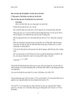
</div><span class="text_page_counter">Trang 18</span><div class="page_container" data-page="18">V load/ V source and R load
</div><span class="text_page_counter">Trang 19</span><div class="page_container" data-page="19">I load and R load
P load and R load
<small>R load</small>
</div><span class="text_page_counter">Trang 20</span><div class="page_container" data-page="20">
VI. CONCLUSIONS-
I load decreases with R load- V load/V source increases with R load-
P load reaches a maximum at the nearest value to the equivalent resistor.</div><span class="text_page_counter">Trang 21</span><div class="page_container" data-page="21">Lab #8: Second Order Circuit
A convenient way to examine the characteristic equation is to compare a given order characteristic equation with a standard form expressed as
+2 ζω<small>n</small>S +ω<small>n</small> =0
ζ is called the damping factor: ω is called the undamped natural resonant frequency. If
ζ < 1 the system response is underdampedζ = 1 the system response is criticallyζ > 1 the system response is overdamped
With (1) and (2), solving the equation we have:
ω<small>n</small>=
√
1LC2 ζω<small>n</small>=<sup>Rtotal</sup>III. EQUIPMENT AND PARTS LIST
- Digital multimeter (DMM)- DC power supply</div><span class="text_page_counter">Trang 22</span><div class="page_container" data-page="22">- Circuit breadboard- Resistors- Pulse generator- Oscilloscope- Capacitor- Inductor
IV. EXPERIMENT RESULTS
1. Circuit for experiment- Actual experiment data:
2. Experiment results- Critically damped3. Calculation
ω<sub>n</sub>=
√
150 . 1 0<small>−3</small>.20 . 1 0<small>−6</small>=100
</div><span class="text_page_counter">Trang 23</span><div class="page_container" data-page="23">2 ζω<small>n</small>=<sup>Rtotal</sup><sub>L</sub> = <sup>50</sup>50 ×1 0<small>−3</small>=1 0<small>3</small>=> ζ¿<sup>1</sup>
</div>