report for final exam topic an automatic sliding door
Bạn đang xem bản rút gọn của tài liệu. Xem và tải ngay bản đầy đủ của tài liệu tại đây (3.66 MB, 26 trang )
<span class="text_page_counter">Trang 1</span><div class="page_container" data-page="1">
<b> HANOI UNIVERSITY OF SCIENCE AND TECHNOLOGY SCHOOLINFORMATION AND COMMUNICATION TECHNOLOGY </b>
──────── * ───────
<b>REPORT FOR FINAL EXAM</b>
<b>Topic : An Automatic Sliding Door</b>
<b> </b>
<b>Instructor : PHD Nguyễn Thị Phương Mai Team members : Nguyễn Thị Hạnh - 20198295</b>Lê Văn Nhuận - 20198320 Đỗ Quốc Tuấn Anh -20198279
<i> </i>
<i><b><small> </small></b></i>
</div><span class="text_page_counter">Trang 2</span><div class="page_container" data-page="2"><b> Declaration of Originality</b>
My team hereby declares that the project is called automatic doorour work, and that it has not been plagiarized from other sources. All sources used in this work, including books, articles, websites and other materials, are properly credited. Any citations h, and all references were included in the bibliography or reference list under the report.
My team also declares that all other contributions or collaborations are equal and has been very specific in the report. Our team confirms that this work has not been submitted for any other degree or qualification, and that it represents our original ideas and research. Any similarities between this work and other works are purely coincidental, or have been acknowledged and properly cited.
<b>Individual Contributions </b>
Lê Văn Nhuận 20198320 Leader.
System desgin (main), hardware design(main), make report, presentation Nguyễn Thị Hạnh 20198295 Software design (Flowchart), hardware
design(support), simulation, make report, FSM controller…
Đỗ Quốc Tuấn Anh 20198279 System design(support), Software design (Fsm), make report, simulation(support)....
All members are fully engaged, enthusiastic in their work and complete the schedule assigned by the team leader
<b>Introduction</b>
</div><span class="text_page_counter">Trang 3</span><div class="page_container" data-page="3">The figure of the automatic door in life can be seen everywhere. The main working principle of the automatic door is to sense whether there is an object passing through the sensing device at the top of the door and the auxiliary infrared sensing device on the side of the door frame, giving the door a switch signal and then programmable control. The device, the frequency converter, the drive motor and the transmission control the movement of the door leaf to realize the function of opening and closing the door.
The design of this paper is an automatic door applied to public places such as shopping malls and high-end hotel entrances and exits, which require strong security and practicality. Integrating automatic door scenes and usage habits in daily life, this paper designs the most used automatic sliding door. The automatic sliding door uses the inductive switch and safety grating to realize automatic control. At the same time, the manual control is realized by using the operation buttons, and the use is made. Auxiliary devices such as backup power supply to meet the needs of different situations of adult traffic.
The project is following the design cycle for engineering, which has five main phases, like the one below.
Figure 1: Engineering Design Cycle
Automatic Sliding Door has these main phases: researching, modeling, implementing , measuring, and communicating . They begin with research, which is constructive analysis and criticism of existing work. It defines problems such as quantitative measures , qualitative values, and so on. Last but not least , it also helps them identify the necessary issues that must be solved fora cutting edge system. After the initiation phase, model, deploy, and measureResponsible for the design phase. In addition, during the communication phase,Based on the evaluation results and measured performance, recommendations for improvements should be made. In general, documents, communications andEvaluation are necessary steps to ensure the success and continuous
improvement of automatic doors
I.Researching...5
</div><span class="text_page_counter">Trang 5</span><div class="page_container" data-page="5">An automatic door is a door that automatically opens when someone approaches, instead of having to open it manually with a doorknob or barricade.Advantages of automatic doors:
1. For people in wheelchairs and other people with disabilities, automatic doors are a huge benefit, as conventional doors can be very difficult to use. May not be able to open doors normally when in a wheelchair or navigating with crutches.
2. In hospitals and scientific laboratories, automatic doors can be used to secure an area by ensuring that doors are always closed, while reducing the risk of cross-contamination by people not needing to control the door to go through.3. Automatic doors can also be useful in warehouses and other facilities where people are constantly busy, contributing to safety and efficiency by making it easier for people to move around.
4. It reduces human labor and prevents inconvenience.
This project is a standalone "Small Scale Automatic Door". The main purpose of the project is to control the opening and closing of the door in the room, counting the number of people in the room, turning the lights ON if there are people and turning the lights OFF if no one is present. The use of embedded technology makes this closed-loop feedback control system efficient and reliable.
<b>II. Modeling</b>
<b>1.Flow chart</b>
</div><span class="text_page_counter">Trang 6</span><div class="page_container" data-page="6"><b>2.FSM</b>
</div><span class="text_page_counter">Trang 7</span><div class="page_container" data-page="7">Front pad detects a person about to walk through Rear pad detects a person standing behind the door
● Two <b>states</b> for the door: + Open
+ Closed
● Four possible <b>inputs</b>: + Front
+ Rear + Both + Neither
State Diagram for automatic door controller:
State transition table for automatic door controller:
</div><span class="text_page_counter">Trang 8</span><div class="page_container" data-page="8"><b>3.Physical Law</b>
Active Infrared sensors transmit and measure the reflection levels ofinfrared light. A change in the properties of the reflected wave indicatesthat a person or object is within the detection area, prompting the sensorrelay activation.
They take a snapshot of the reflected infrared signal from the ground andcontinuously compare it to reflection levels into the sensor during dailyuse. For example, when a person or object enter the detection area theintensity of reflected infrared light – when compared to that from theground, increases causing the sensor to detect.
Active infrared sensors can detect both movement and static presencemaking them ideal for opening doors whilst maintaining pedestriansafety.
Infrared rays are used in automatic door systems such as automatic sliding doorsor induction doors to detect the presence of people or obstacles during the operation of the door. Here are some key characteristics of infrared in automaticdoor application:
1. Detectability: Infrared ray can detect movement and presence of people or obstacles in its active area. When there is a problem again, the infrared rays are
</div><span class="text_page_counter">Trang 9</span><div class="page_container" data-page="9">blocked and the automatic door system will be activated to pause or change the direction of travel.
2. Sensitivity: The infrared system can be adjusted for custom sensitivity, from detecting large movements to the smallest movements. This allows adjustments to avoid unwanted effects or minimize detection of small unimportant objects.3. Range of operation: The range of infrared rays can be adjusted according to the specific requirements of the automatic door system. Typically, the operating range can be from a few meters to several meters, depending on the design and intended use of the automatic door.
4. Speed of response: Infrared systems typically have a fast response rate, allowing for immediate detection and response. When there is a problem again, the automatic door can pause or change the direction of travel for a short period of time.
5. Ability to work in low light conditions: Infrared rays can work well in low light conditions or there is not enough ambient light to use other developed technologies such as cameras. Therefore, it is suitable for automatic door applications in low-light or night-time environments.
The above special features make infrared a popular and effective technology to make automatic doors smart and safe.
</div><span class="text_page_counter">Trang 10</span><div class="page_container" data-page="10"><b> 4.FSM controller</b>
<b> 5. Input/Output signals</b>
</div><span class="text_page_counter">Trang 11</span><div class="page_container" data-page="11"><b>III. Implementing </b>
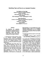
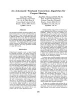
<b> In this paper, the drive motor drives the transmission device to realize the </b>
opening and closing of the automatic door. The operation of the motor is realized by the AC frequency controlled by the PLC to control the frequency converter to supply the motor. The advantages of this design are easy operation, stable operation and high real-time performance. Compared with other types of motors, more mature AC motors can control cost, have stable torque output and a larger speed range. Improve the stability of the long-term operation of the automatic door, the system hardware components.
Figure 2. Hardware structure of the system.
The transmission of the automatic door is mainly composed of a drive motor, a transmission belt and a transmission pulley. Considering the convenient installation and maintenance, the transmission only occupies a small part of the whole system. For example, the pulley that drives the door body needs to be fixed outside the wall to be detachable structure. The three-phase asynchronous motor is selected as the drive motor. Passing three-phase symmetrical
alternating current into the stator winding of the motor generates a circular rotating magnetic field. In the magnetic field, the rotor winding cuts the magnetic field to generate an induced current, and the rotor winding in the closed path also generates an electromagnetic force. Under the interaction of thetwo magnetic fields, the motor, the electromagnetic torque in the same direction as the rotating magnetic field is formed on the rotating shaft, so that the rotor of the motor rotates.
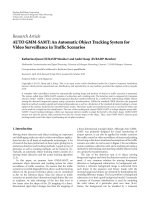
</div><span class="text_page_counter">Trang 12</span><div class="page_container" data-page="12">Name Function
(1) Door operator An automatic door operator is a set of drivingdevices and controllers that opens/closes thedoor. It includes components such as gear motor
and door controller.
(2) Maintenance switch The power to the door operator can be turnedon/off easily during the maintenance of the
door.
(3) Activation sensor Activation sensors are used to activate thedoor's openings and closings by sending a signal
to the door operator.
[Notes] The above figure shows different typesof activation sensors. The appropriate activationsensor shall be selected according to the use and
environment.
(4) Safety sensor Safety sensors such as beam sensors detectpeople or objects on the door track, where it isdifficult to be detected by activation sensors.
</div><span class="text_page_counter">Trang 13</span><div class="page_container" data-page="13">(5) Fanlight Glass or other materials mounted between theceiling and the header.
(6) Transom Door operator is installed inside the header box.(7) Sliding door panel Materials such as tempered glass, aluminum and
stainless steel are often used. (8) Fixed door panel Non-sliding door panel
(9) Lock Lock for the door. Figure 3. Automatic Sliding Door Components
</div><span class="text_page_counter">Trang 14</span><div class="page_container" data-page="14">activation mode can be selected.
<b>EOS Emergency Operating System</b>
Locking/Unlocking Condition Fail safe (unlock at power off) Structure of Locking Mechanism Electromagnetic brake with tooth Locking/Unlocking Monitor Output When the power is on :
Make or Break can be selected Forced Unlocking Input Non-voltage a / b contact
</div><span class="text_page_counter">Trang 15</span><div class="page_container" data-page="15">PL-T10U Pulley Lock
Program switch APS-A10
Applicable Operator NATRUS / NET-DSPower Voltage 12VDC±10%Current Consumption Max 80mA
Security Code PasscodeProgram Mode Auto, Hold open, One-way,
Manual, Night (Lock)
Language English, Chinese, Korean, Thai, Vietnamese,Indonesian, Russian
Product Name NS-A02
Detection Method Motion & Presence Detection Near Infrared(reflection method )
Mounting Height (MAX) 2.0 to 4.0m as activation sensor / 2.0 to 3.5m asprotective sensor
</div><span class="text_page_counter">Trang 16</span><div class="page_container" data-page="16">Detection Area (MAX) W 3.05m x D 2.09m (Mounting height 2.5m) Output Ratings NET-DS connector
Power Voltage / PowerConsumption
12VDC / 120mA or less
<b>Activation sensor (header recessed type)</b>
Product Name NP-10B Beam Sensor
Detection Method Near infrared reflection method (Motion andpresence detection)
Mounting Height (MAX) FL+600mm
Detection Area (MAX) Distance between transmitter and receiver: 5 m Output Ratings No-voltage relay contact 1a 50V DC 0.1A
(resistance load) Power Voltage 100V AC Power Consumption 4VA or less
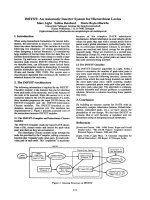
</div><span class="text_page_counter">Trang 17</span><div class="page_container" data-page="17"><b>Figure 4. Sensor type by its place</b>
<b>1.Transom embedded </b>
Product Name Detection Area (MAX) Mounting Height (MAX)
NS-A01 <sub>(Mounting height 2.5m) </sub><sup>W 3.05m x D 2.09m</sup>
2.0 to 4.0m as activationsensor / 2.0 to 3.5m as
protective sensor
<b>Spec </b>
Product Name <sup>NS-A01 </sup>
Detection Method <sup>Motion & Presence Detection Near Infrared reflection</sup>(method )
Mounting Height(MAX)
2.0 to 4.0m as activation sensor / 2.0 to 3.5m as protectivesensor
</div><span class="text_page_counter">Trang 18</span><div class="page_container" data-page="18">Detection Area (MAX) <sup>W 3.05m x D 2.09m (Mounting height 2.5m) </sup>Output Ratings <sup>NET-DS connector </sup>
Power Voltage / Power
Consumption <sup>12VDC / 120mA or less </sup>
Remarks
Function: Spot-by-spot setup Safety test before closing
Trouble indication Full-color LED display
Eco mode Touchless switch mode
Available for Circular/Folding door as well
protective sensor
Spec
</div><span class="text_page_counter">Trang 19</span><div class="page_container" data-page="19">Product Name <sup>NS-A02 </sup>Detection Method
Motion & Presence Detection Near Infrared reflection(method )
Mounting Height(MAX)
2.0 to 4.0m as activation sensor / 2.0 to 3.5m asprotective sensor
Detection Area (MAX) <sup>W 3.05m x D 2.09m (Mounting height 2.5m) </sup>Output Ratings <sup>NET-DS connector </sup>
Power Voltage / Power
Consumption <sup>12VDC / 120mA or less </sup>
<b>3.Ceiling mount </b>
Product Name Detection Area (MAX) Mounting Height (MAX)
NS-A04 <sub>(Mounting height 3.0m) </sub><sup>W 3.04m x D 2.37m</sup>
2.0 to 4.0m as activationsensor / 2.0 to 4.0m as
protective sensor
Spec
</div><span class="text_page_counter">Trang 20</span><div class="page_container" data-page="20">Product Name <sup>NS-A04 N Search </sup>Detection Method
Motion & Presence Detection Near Infrared(reflection method )
Mounting Height (MAX) <sup>2.0 to 4.0m as activation sensor / 2.0 to 4.0m as</sup>protective sensor Detection Area (MAX) <sup>W 3.04m x D 2.37m (Mounting height 3.0m) </sup>
Output Ratings <sup>NET-DS connector </sup>Power Voltage / Power
Consumption <sup>12VDC / 120mA or less </sup>
FL+600mm
Spec
Product Name <sub>NP-10B Beam Sensor </sub> <sub>NP-10LB Beam Sensor </sub>
</div><span class="text_page_counter">Trang 21</span><div class="page_container" data-page="21">Detection Method <sup>Near infrared reflection method (Motion and presence</sup>detection) Mounting Height (MAX) <sup>FL+600mm </sup>
Detection Area (MAX)
Distance betweentransmitter and receiver:
5 m
Distance betweentransmitter and receiver:
8 m Power Voltage <sup>100V AC </sup>Power Consumption <sup>4VA or less </sup>
<b>5.Pillar/Wall mount </b>
Product Name <sup>Detection Area</sup><sub>(MAX) </sub> <sup>Mounting Height</sup><sub>(MAX) </sub>
HDS-4P Push Button Switch
Spec
Product Name <sup>HDS-4P Push Button Switch </sup>Detection Method <sup>Pressure detection (Push-button type) </sup>Operation Method Push button operation
</div><span class="text_page_counter">Trang 22</span><div class="page_container" data-page="22">Standard Mounting
Method <sup>Embedded in the wall </sup>
<b>6.Foot switch </b>
<b>6.Footswitch </b>
Product Name Detection Area (MAX) <sup>Mounting Height</sup><sub>(MAX) </sub>
FT-A30 Foot Switch
Spec
Product Name <sup>FT-A30 Foot Switch </sup>Detection Method <sup>Photoelectric type </sup>Operation Method <sup>Toe insert type </sup>Standard Mounting
Method <sup>Embedded in wall </sup>Power Voltage <sup>12VDC </sup>Power Consumption <sup>65mA or less </sup>
<b>7. Camera</b>
</div><span class="text_page_counter">Trang 23</span><div class="page_container" data-page="23">Product Name Detection Area (MAX) <sup>Mounting Height</sup><sub>(MAX) </sub>
TP-Link Tapo C200 Full HD WifiIP Camera
High Definition video: Capture every detail in crystal clear 1080p.
- Advanced Night Vision Mode: Even at night, the camera can see images at a distance of up to 9 meters.
- Motion Detection and Notifications: Get notified if something suspicious is detected.
- Light and Sound Alarm: Activate lights and sound effects to scare away uninvited guests.
</div><span class="text_page_counter">Trang 24</span><div class="page_container" data-page="24">- Two-Way Audio: Communicate with others using the built-in microphone and speaker.
- Safe Storage: Supports MicroSD Card (up to 128 GB).
There are 14 PIR sensors mounted on the acquisition nodes. In front of each sensor, the customized mask is installed to define the effective sensing area as 5 degrees. After amplification and band-pass filters, the weak output signal detected by PIR sensors is sent to ADC for converting the analog signal into the digital signal. Then the single-chip will pack the digital signal from each sensor and transmit the data to the gateway node through wireless. Four acquisition nodes are deployed at four corners of a square space, and the wireless node should be placed near he site. Although, any of two neighboring
nodescanperform positioning; however, the positioningerror willbecome larger as the distance of the target and a sensor nodegetting larger. Through such deployment with4sensornodes, we can get a relatively small positioning errorThe D205B model of PIRsensor. Whenapedestrian walked into the sensing area,the amplitudeofthe output signal is about 1-5 mV and the energy is mainly distributed in the frequency range of 0.1 Hz-10 Hz. In order to effectively
</div>