project report scara robot control system design
Bạn đang xem bản rút gọn của tài liệu. Xem và tải ngay bản đầy đủ của tài liệu tại đây (6.91 MB, 61 trang )
<span class="text_page_counter">Trang 1</span><div class="page_container" data-page="1">
<b>HANOI UNIVERSITY OF SCIENCE AND TECHNOLOGY SCHOOL OF MECHANICAL ENGINEERING </b>
<b>Hanoi, 1/2022 </b>
</div><span class="text_page_counter">Trang 2</span><div class="page_container" data-page="2">2 Table of Contents
Control system design problem ... 6
Chapter 1: OVERALL OF SCARA ROBOT... 7
1.1. General of SCARA Robot: ... 7
1.2. Working principle and speci c parameters analysis of SCARA Robot: ... 9
1.2.1. Working principle of control system: ... 9
1.2.2. Components in the control system of robot: ... 9
1.3. Robot Model design: ... 10
Chapter 2: KINETICS AND KINEMATICS OF SCARA ROBOT ... 12
2.1. The kinema cs analysis of SCARA Robot: ... 12
3.2. Robot trajectory design: ...22
3.2.1. Theory of movement trajectory:...22
3.2.2. Design third-order trajectory in joint space:...23
3.2.3. Design of third-order trajectory in task space: ... 30
Chapter 4: ROBOT LINK MODELING ... 34
4.1. Modeling and nd transfer func on for a robot link: ... 34
4.1.1. Calculate transfer func on of power transmission for each link: ... 38
4.1.2. Construct Simulink diagram to model one link of the robot: ... 47
4.2. Simula on and evaluate stability and other quality speci cs: ...48
4.2.1. Kinema cs simula on for one link, and the whole robot with Simulink: ... 48
4.2.2. Calculate steady state error and evaluate response quality: ...49
</div><span class="text_page_counter">Trang 3</span><div class="page_container" data-page="3">Chapter 5: CONTROL SYSTEM DESIGN ... 52
5.1. PID controller: ... 52
5.2. Modeling control system for SCARA robot: ... 53
5.3. Determine parameters for PID controller: ... 54
Reference ... 61
</div><span class="text_page_counter">Trang 4</span><div class="page_container" data-page="4">
4
Figure 1. Model of a SCARA Robot ... 7
Figure 2. Sensor con gura on on SCARA Robot... 9
Figure 3. General diagram of control system for SCARA Robot ... 10
Figure 4. Ball-screw ... 10
Figure 5 Timing belt ...11
Figure 6 Working space in XY plane ... 21
Figure 7 Working space in 3D coordinate ... 22
Figure 8. Joint variables diagram of the problem ... 25
Figure 9. Mark points of pick and place object applica on ... 25
Figure 10. Simulink program for determine set of joint variables at mark point ... 26
Figure 11. Trajectory planning block ... 27
Figure 12. Joint variables versus me diagram ... 27
Figure 13. Joint velocity versus me diagram ... 28
Figure 14. Joint accelera on versus me diagram ... 28
Figure 15. Simulink program for path planning of SCARA robot with forward simula on ...29
Figure 16. Theore cal working trajectory of the robot for the task in 3D coordinate ... 29
Figure 17. Mark points of pick and place object applica on ... 30
Figure 18. Simulink program for path planning in task space...31
Figure 19. Joint variables diagram ... 32
Figure 20. Joint velocity diagram ... 32
Figure 21. Joint accelera on diagram ... 33
Figure 22. End e ector trajectory in 3D space ... 33
Figure 23. Control system block diagram ...34
Figure 24. General diagram of a robot link with gear transmission ... 34
Figure 25. General diagram of electromechanical system for a robot link ... 35
Figure 26. Ball-screw system ... 37
Figure 27. Block diagram of ball-screw ... 38
Figure 28. Model for total transfer func on of link 1 ... 38
Figure 29. Model for calculate iner a moment for link 1 ... 39
Figure 30. Mass proper es of subsequent links act on link 1 ... 39
Figure 31. Informa on of motor for link 1 ... 40
Figure 32. Nyquist Diagram of transfer func on G (s) <small>1</small> ...40
Figure 33. Bode diagram of transfer func on G (s) <small>1</small> ... 41
Figure 34. Model for transfer func on of link 2 ...41
Figure 35. Model for calculate iner a moment for link 2 ... 42
Figure 36. Mass proper es of selected part ... 42
Figure 37. Informa on of motor for control sec on 2 ... 43
Figure 38. Nyquist Diagram of transfer func on G (s) <small>2</small> ...43
Figure 39. Bode diagram of transfer func on G (s) <small>2</small> ... 44
Figure 40. Block diagram for total transfer func on of link 3 ... 44
Figure 41. Selected part to calculate iner al moment ... 45
Figure 42. Mass proper es of selected part ... 45
Figure 43. Motor informa on of link 3 ... 46
Figure 44. Nyquist Diagram of transfer func on G (s) <small>3</small> ...46
Figure 45. Bode diagram of transfer func on G (s) <small>2</small> ... 47
Figure 46. Simulink diagram for transfer func on of link 1 servo motor ... 48
Figure 47. Transfer func on of servo motor for link 1 ...48
Figure 48. Simulink model for link 1 with nega ve feedback ... 48
</div><span class="text_page_counter">Trang 5</span><div class="page_container" data-page="5">Figure 49. Simulink model for link 2 with nega ve feedback ... 49
Figure 50. Simulink model for link 3 with nega ve feedback ... 49
Figure 51. Step response for link 1 ... 50
Figure 52. Step response for link 2 ... 50
Figure 53. Step response for link 3 ... 51
Figure 54. Block diagram for one link with controller ...52
Figure 55. Block diagram of a PID controller ... 52
Figure 56. Simulink diagram for complete mo on control of a robot link ... 53
Figure 57. Simulink diagram of controller block ... 53
Figure 58. 3D model of robot imported to Matlab ... 53
Figure 59. Modeling of control system for SCARA robot with Simulink ... 54
Figure 60. Model of SCARA robot in Simulink ... 54
Figure 61. Model for PID tuning and checking for each link ... 54
Figure 62. Block PID controller in Simulink ... 55
Figure 63. PID tuner window ... 55
Figure 64. Step response for link 1 with the set of chosen PID parameters...56
Figure 65. Step response for link 2 with the set of chosen PID parameters...56
Figure 66. Step response for link 3 with the set of chosen PID parameters...57
Figure 67. Diagram of set and real value of joint variable 1 ... 58
Figure 68. Joint variable di erent diagram over me of link 1 ... 58
Figure 69. Diagram of set and real value of joint variable 2 ... 59
Figure 70. Joint variable di erent diagram over me of link 2 ... 59
Figure 71. Diagram of set and real value of joint variable 3 ... 60
Figure 72. Joint variable di erent diagram over me of link 3 ... 60
</div><span class="text_page_counter">Trang 6</span><div class="page_container" data-page="6">
6
Contntntrol srol srol systystystem dem dem desesign pesign pign proroblerobleblem m
Design the control system for a 3 Degree of Freedom SCARA robot. The con gura on of robot is:
<b>Load Reach z-axis transla on </b>
<b>Revolute range Reference Link 1 Link 2 </b>
10 kg 700 mm 300 mm -165<small>o </small>/ 165<small>o </small> -147<small>0</small> / 147<small>o </small> DENSO HM-G Series
Some quality criterion for PID control of each link: - Percent of overshoot for each link less than 20% - Se ling me less than 0.7 s
- Error of steady state equal 0 for link control system with step input.
</div><span class="text_page_counter">Trang 7</span><div class="page_container" data-page="7">Chaptaptapter 1:er 1:er 1: OVE OVE OVERALRALL OFRALL OFL OF SCAR SCARA ROB SCARA ROBA ROBOT OT
<b>1.1.1.De ni on of SCARA Robot:</b>
SCARA Robot is abbrevia on of Selec ve Compliance Assembly Robot Arm or Selec ve Compliance Ar culated Robot Arm. It normally con gured as a 4 DOF Robot. With the parallel con gure of revolute joints, SCARA Robot is used widely in vertical assembly task or in parallel plane (selec ve direc on) applica on.
<b>1.1.2.Purpose of design: </b>
In this project, the goal is to design an industrial use SCARA Robot with considera on about both economically and e ciency. The Robot will be controlled with familiar stepper motor or servo motor and control circuit which should be available on the market. Control program for the robot should be available for every personal computer for convenient and versa le use of the robot. This program will be using G-code for control the SCARA robot.
<b>1.1.3.Requirements of SCARA robot: </b>
Robot is designed to become machines with high accuracy and exibility. Therefore, Robot in general or SCARA in speci c, are used as replacement for the tradi onal workers in factory nowadays. To ful ll this purpose, robot design must follow some technical parameters given. These parameters will demonstrate and ensure the ability of robot to handle some certain tasks. For example, some technical speci ca ons of SCARA Robot Adept One XL are shown below:
Figure 1. Model of a SCARA Robot
<b> Maximum Reach: 950 mm Working area of each joint: </b>
- Joint 1: ± 150°- Joint 2: ± 140°- Joint 3: 203 mm - Joint 4: ± 270°
<b>Maximum velocity of each link: </b>
</div><span class="text_page_counter">Trang 8</span><div class="page_container" data-page="8">8
<b>- Joint 1: 650°/s - Joint 2: 920°/s - Joint 3: 1200 mm/s - Joint 4: 3300°/s Repeatability: </b>
- (x, y): ±0.025 𝑚𝑚- (z): ±0.038 𝑚𝑚- Theta: ±0.05°
<b>Maximum load: 5 kg 1.1.4.Mechanical System: </b>
SCARA is one of standard con gura ons for robot arm. In primary design procedure, we have some speci ca ons for the robot as follow:
- Number degree of freedom: 3 - Load: 10 kg
- Reach: 700 mm
- Repeatability: (x,y) ±0.02 𝑚𝑚, (z) ±0.01 𝑚𝑚- Maximum velocity of end e ector: 9570 mm/s - Transmission of nal link: Ball screw
<b>1.1.5.Electronics System: </b>
Electronics components for the system must depend on the type of motor being used in the robot. To obtain high accuracy, stepper motor or servo motor will be used in the general transmission. An important part of electronics system design is design control circuit for servo motor. This part and the control program are the two most important factors will a ect the e ciency of robot. In this project, we only focus on the control program of servo motor.
Some primary factor before design must be no ced are : - Type of motor: Unipolar or Bipolar
- Working principle: L/R or PWM - Working mode: Full or half step - Characteriza on of torque and velocity
<b>1.1.6.Control program: </b>
The control program for the robot must capable of performing these tasks: - Con nuous path calcula ng
- Joint-interpolated mo on - Arc-interpolated mo on - Linear-interpolated mo on
- Start and stop mo on of all axis at the same me
<b>Requirements for control program of robot: The control system a er design must be </b>
checked with some requirements for quality con rma on. - Percent of overshoot: less than 20%
</div><span class="text_page_counter">Trang 9</span><div class="page_container" data-page="9">- Se ling me: less than 0.7 s - Steady state error: 0
<b>Robot: </b>
<b>1.2.1.Working principle of control system: </b>
Firstly, all sensors will obtain the informa on, characteris c of the target based on the se ng program. For example, informa on about color and weight of the target, distance to the loca on of object will be collected through sensors.
From these informa on, control program of the robot will calculate the parameters, create and send the command to the control system to perform the opera on with robot arm in a fast and precise manner.
<b>1.2.2.Components in the control system of robot: </b>
-
Motors: The choice of motors is made from mechanical system design of SCARA robot.-
Sensors: For SCARA robot, sensors must include 2 rota on angle sensor (SR-1, SR-2) for two revolute joints, a linear mo on sensor (SP-3) for the third joint and a force sensor (SF-4) for the jaw at end e ector. Another sensor might be added for be er control of the robot or other applica on may require. The model of sensor on the robot can be shown as:<small>Figure 2. Sensor configuration on SCARA Robot </small>
-
Power supply</div><span class="text_page_counter">Trang 10</span><div class="page_container" data-page="10">10
<small>Figure 3 General diagram of control system for SCARA Robot. </small>
- Control program: This can be done with available applica on as LinuxCNC, or program wri en on MatLab/Simulink.
With the reference of DENSO HM 4070G robot, we had built a 3 DOF SCARA robot model, which suitable with the technical speci ca on given.
(Image of robot model)
Transmission system of the robot model include:
- Ball-screw transmission: This mechanical pair convert rotation mo on into transla on mo on. Lead screw also able to perform the same conversion with high accuracy and transmission ra o. However, lead screw rarely use for transmission of primary mo on due to its low e ciency.
<small>Figure 4. Ball-screw</small>
- Belt transmission: This is one of the most common type of transmission in Mechanical. Belt system transmits torque and velocity between two sha s with larger distance than gear transmission. Belt transmission has several advantages as: Low noise, low shock, large distance transmission, no lubrica on needed, and low maintain fee.
</div><span class="text_page_counter">Trang 11</span><div class="page_container" data-page="11"><small>Figure 5 Timing belt </small>
</div><span class="text_page_counter">Trang 12</span><div class="page_container" data-page="12">12
Chaptaptapter 2:er 2:er 2: KINE KINE KINETICSTICSTICS AND K AND K AND KINEMINEMATICINEMATICATICSSSSS OF OF OF SC SC SCARARA ROBARA ROBA ROBOT OT
<b>2.1. The kinema cs analysis of SCARA Robot: </b>
<b>2.1.1. Forward kinema cs: </b>
We represent the SCARA robot by the kine cs diagram for analysis as follow:
Figure 5. Kinematics diagram of SCARA robot
From the kinema cs diagram of SCARA robot above (Figure 8), we create the D-H parameters table as follow:
θ<small>i</small>: angle of rota on of frame (i-1) around axis z for axis x to match axis x <small>i-1i-1i.</small>
d<small>i</small>: distance of origin of 2 frames (i-1) and (i) in z axis direc on. <small>i-1 </small>
α<small>i</small>: angle of rota on of frame (i-1) around x axis for z to match z . <small>ii-1i</small>
a<small>i</small>: distance of origin of 2 frames (i-1) and (i) in x axis direc on <small>i</small>
By using D-H table and Denavit Hartenberg shortcut, we can create the homogenous –transforma on matrix. If we denote <small>i-1</small>H<small>i </small>as the homogenous transforma on matrix from frame (i-1) to frame i then:
</div><span class="text_page_counter">Trang 13</span><div class="page_container" data-page="13"><small>i-1</small>H<small>i </small>= [
cos(𝜃<sub>𝑖</sub>) −𝑐𝑜𝑠(𝛼<small>𝑖</small>)𝑠𝑖𝑛 𝜃( <small>𝑖</small>) 𝑠𝑖𝑛(𝛼<small>𝑖</small>)𝑠𝑖𝑛 𝜃( <small>𝑖</small>) 𝑎<small>𝑖</small>cos(𝜃<sub>𝑖</sub>)𝑠𝑖𝑛 𝜃( <sub>𝑖</sub>) 𝑐𝑜𝑠(𝛼 )cos (𝜃<sub>𝑖</sub> <sub>𝑖</sub>) −𝑠𝑖𝑛(𝛼 )cos (𝜃<sub>𝑖</sub> <sub>𝑖</sub>) 𝑎 𝑠𝑖𝑛 𝜃<sub>𝑖</sub> ( <sub>𝑖</sub>)
<b>Posi on of end e ector in frame 0 (denoted as ) is: </b><small>0</small>r<small>E</small>
<small>0</small>r<small>E</small> = [<sup>𝑎</sup><sup>2</sup>
cos(𝑞<sub>1</sub>+ 𝑞<sub>2</sub>) + 𝑎 cos (𝑞<sub>1</sub> <small>1</small>)𝑎<sub>2</sub>sin 𝑞(<sub>1</sub>+ 𝑞<sub>2</sub>) + 𝑎 sin (𝑞 )<sub>1</sub> <sub>1</sub>
𝑑 + 𝑑 + 𝑞<sub>1</sub> <sub>2</sub> <sub>3</sub>
</div><span class="text_page_counter">Trang 14</span><div class="page_container" data-page="14">14
<b>Orienta on of end e ector (</b>R<small>E</small>) is:
<small>0</small>R<small>E</small> = [<sup>cos (𝑞</sup>sin (𝑞<sup>1</sup><sub>1</sub><sup>+ 𝑞</sup>+ 𝑞<sup>2</sup><sub>2</sub><sup>) −sin (𝑞</sup>) cos (𝑞<sub>1</sub><sup>1</sup><sup>+ 𝑞</sup>+ 𝑞<sub>2</sub><sup>2</sup><sup>) 0</sup>) 0
] (Eq. 2.6) - Angular velocity:
(𝒗<sub>𝐸</sub><small>0</small>)<small>𝑞</small>= [0
0𝑞<sub>1</sub> + 𝑞<sub>2</sub> <sup>] ; </sup>
(Eq. 2.7) Accelera on of end e ector:
- Linear accelera on:
(Eq. 2.8) - Angular accelera on:
𝑎<small>𝑞30</small> = [0
0𝑞<sub>1</sub> + 𝑞<sub>2</sub> <sup>] ; </sup>
(Eq. 2.9)
With the geometric parameters and limita on of joint variable as:
Kinema cs parameter: {
𝑑<sub>1</sub>= 300 𝑚𝑚𝑑<sub>2</sub>= 100 𝑚𝑚𝑎<sub>1</sub>= 350 𝑚𝑚𝑎<small>2</small>= 350 𝑚𝑚Joint variable set: 𝒒 = [𝑞<sub>1</sub>, 𝑞 , 𝑞 ]<sub>2</sub> <sub>3</sub><small>𝑇</small>, where:
𝑞<small>1</small>= (−165° ÷ 165°); 𝑞<sub>2</sub>= (−147° 147°÷ );𝑞<sub>𝟑</sub>= (−400 ÷ 0 𝑚𝑚) Replacing into Eq. 2.4, we obtain:
𝑥 = 350 cos(𝑞<sub>1</sub>+ 𝑞<sub>2</sub>) + 350cos(𝑞<sub>1</sub>) (𝑚𝑚)𝑦 =350sin 𝑞(<sub>1</sub>+ 𝑞<sub>2</sub>) + 350sin 𝑞(<sub>1</sub>) (𝑚𝑚)𝑧 =400+ 𝑞<sub>3</sub> (𝑚𝑚)
(Eq. 2.10)
</div><span class="text_page_counter">Trang 15</span><div class="page_container" data-page="15">Refer to Eq. 2.4, we have set of equa ons:
𝑎<sub>2</sub>cos(𝑞<sub>1</sub>+ 𝑞<sub>2</sub>) + 𝑎<sub>1</sub>cos(𝑞<sub>1</sub>) = 𝑥<sub>𝑒</sub> (1)𝑎<sub>2</sub>sin 𝑞(<sub>1</sub>+ 𝑞<sub>2</sub>) + 𝑎<small>1</small>sin 𝑞(<sub>1</sub>) = 𝑦<small>𝑒</small> (2)𝑑 + 𝑑 + 𝑞 = 𝑧<sub>1</sub> <sub>2</sub> <sub>3</sub> <sub>𝑒</sub> (3)From (1) and (2):
Then we obtain two equa ons with two unknown sin(q ) and cos(q <small>11</small>):
From two equa ons:
Using Crammer’s rule, the unknowns are found to be:
</div><span class="text_page_counter">Trang 16</span><div class="page_container" data-page="16">16 ↔ 𝑞<sub>1</sub>= arctan (<sup>sin(𝑞</sup><sup>1</sup><sup>)</sup>
cos(𝑞<sub>1</sub>)<sup>) = tan</sup><sup>−1</sup><sup>(</sup>
𝑎<sub>1</sub>𝑦<small>𝑒</small>+ 𝑎<sub>2</sub>(𝑦<sub>𝑒</sub>𝑐𝑜𝑠(𝑞<small>2</small>) − 𝑥 sin (𝑞<sub>𝑒</sub> <sub>2</sub>))
𝑎 𝑥<sub>1 𝑒</sub>+ 𝑎<sub>2</sub>(𝑥<small>𝑒</small>𝑐𝑜𝑠(𝑞 ) + 𝑦<sub>2</sub> <sub>𝑒</sub>sin (𝑞<sub>2</sub>))<sup>) (Eq. 2. )</sup><sup>21 </sup>Subs tute real parameters of robot to set of equa ons:
𝑞<sub>1</sub>= tan<small>−1</small>(<sup>350𝑦</sup><small>𝑒</small>+ 350(𝑦<sub>𝑒</sub>𝑐𝑜𝑠(𝑞<sub>2</sub>) − 𝑥 sin (𝑞<sub>𝑒</sub> <sub>2</sub>))350𝑥<sub>𝑒</sub>+350(𝑥 𝑐𝑜𝑠(𝑞 + 𝑦<sub>𝑒</sub> <sub>2</sub>) <sub>𝑒</sub>sin (𝑞<sub>2</sub>))<sup>)</sup>𝑞<sub>2</sub>= cos<small>−1</small>(𝑥<sub>𝑒</sub><sup>2</sup>+ 𝑦<sub>𝑒</sub><small>2</small>− 350 − 350<small>22</small>
<small>𝜕𝑞𝑖</small> )<sup>𝑇</sup>− (<sup>𝜕𝑇</sup>
<small>𝜕𝑞𝑖</small>)<sup>𝑇</sup>= − (<sup>𝜕𝜋</sup>
<small>𝜕𝑞𝑖</small>)<sup>𝑇</sup>+ 𝑄<sub>𝑖</sub><small>∗</small> (Eq. 2.23) This equa on is equivalent to the general form of dynamical equa on:
Where:
<b>V – velocity coupling vector G – gravita onal forces Q – vector generalized forces </b>
M – manipulator iner a matrix
By denote as posi on vector for center of mass of link j, represented in frame i. Then <small>i</small><b>p</b><small>cj</small>
assuming that all links are homogeneous with rela vely small cross sec on compare to the length. The posi on vectors of the centers of mass are given by:
<small>1</small><b>p</b><small>c1</small> = [-a1/2, 0, 0]<small>T</small>,
<small>2</small><b>p</b><small>c2</small>= [-a2/2, 0, 0]<small>T</small>,
<small>3</small><b>p</b><small>c3</small> = [0, 0, 𝑙/2]<small>T</small>, Where:
𝑙 is the third link length. 2.2.1.1. Link inertia matrices:
As the assump on about the geometry shape of link and the orienta on of each link in kinema cs diagram in Figure 8, we have the link iner a matrices about their centers of mass and expressed in their respec ve link frames as:
</div><span class="text_page_counter">Trang 17</span><div class="page_container" data-page="17"><small>12</small>𝑚<small>1</small>𝑎<small>1</small> [<sup>0 0 0</sup>0 1 00 0 1],
<small>2</small>𝐼<sub>2</sub>=<sup>1</sup><sub>12</sub>𝑚<sub>2</sub>𝑎<sub>2</sub> [<sup>0 0 0</sup>0 1 00 0 1],
<small>3</small>𝐼<sub>3</sub>=<sup>1</sup><sub>12</sub>𝑚<sub>3</sub>𝑎<sub>3</sub> [<sup>1 0 0</sup>0 1 00 0 0]
(Eq. 2.25) Where:
<sup>i</sup>𝐼<small>𝑗</small> is the iner a matrices of link j in frame i
By mul ply the iner a matrices above <small>i</small>𝐼<sub>𝑖</sub> with the rota on matrices <small>0</small>R<small>i</small>, we have the iner a matrices about their centers of mass and expressed in the base frame as:
𝐼<sub>𝟏</sub>= <sup>1</sup>
12<sup>𝑚</sup><small>1</small>𝑎<small>1</small> [ <sup>𝑠𝑖𝑛(𝜃</sup><sup>1</sup>
)<small>2</small> −𝑠𝑖𝑛 𝜃(<sub>1</sub>)𝑐𝑜𝑠 𝜃(<sub>1</sub>) 0−𝑠𝑖𝑛 𝜃(<sub>1</sub>)𝑐𝑜𝑠 𝜃(<sub>1</sub>) 𝑐𝑜𝑠(𝜃<sub>1</sub>)<small>2</small> 0
],
𝐼<sub>𝟐</sub>= <sup>1</sup>12<sup>𝑚</sup><small>2</small>𝑎<sub>2</sub> [
𝑠𝑖𝑛(𝜃<sub>1</sub>+ 𝜃<sub>2</sub>)<small>2</small> −𝑠𝑖𝑛 𝜃(<sub>1</sub>+ 𝜃<sub>2</sub>)𝑐𝑜𝑠 𝜃(<sub>1</sub>+ 𝜃<sub>2</sub>) 0−𝑠𝑖𝑛 𝜃(<sub>1</sub>+ 𝜃<sub>2</sub>)𝑐𝑜𝑠 𝜃( <sub>1</sub>+ 𝜃<sub>2</sub>) 𝑐𝑜𝑠(𝜃<sub>1</sub>+ 𝜃<sub>2</sub>)<small>2</small> 0
],
𝐼<sub>𝟑</sub>=<sup>1</sup><sub>12</sub>𝑚<sub>3</sub>𝑙<small>2</small>[<sup>1 0 0</sup>0 1 00 0 0
2.2.1.2. Link Jacobian matrices:
The posi on vectors of the centers of mass of links 1, 2, and 3 with respect to the various link frames and expressed in the base frame are:
<b><small>0</small></b>𝒑<sub>𝑐1</sub><small>∗</small> = [
<b>], </b>
<b><small>0</small></b>𝒑<small>∗</small><sub>𝑐2</sub>= [
𝑎<sub>1</sub>cos(𝜃<sub>1</sub>) +<sup>1</sup><sub>2</sub>𝑎<sub>2</sub>cos(𝜃<sub>1</sub>+ 𝜃<sub>2</sub>)𝑎 sin 𝜃<sub>1</sub> (<sub>1</sub>) +<sup>1</sup><sub>2</sub>𝑎<sub>2</sub>sin(𝜃<sub>1</sub>+ 𝜃<sub>2</sub>)
],
</div><span class="text_page_counter">Trang 18</span><div class="page_container" data-page="18">18
<b><small>2</small></b>𝒑<small>∗</small><sub>𝑐3</sub>= [0
<small>2</small>𝑙],
<b><small>1</small></b>𝒑<small>∗</small><sub>𝑐3</sub>= [
𝑎<sub>2</sub>cos(𝜃<sub>1</sub>+ 𝜃<sub>2</sub>)𝑎<small>2</small>sin 𝜃(<sub>1</sub>+ 𝜃<sub>2</sub>)𝑑<sub>3</sub>+<sup>1</sup><sub>2</sub>𝑙
],
<b><small>0</small></b>𝒑<small>∗</small><sub>𝑐3</sub>= [
𝑎<sub>1</sub>cos(𝜃<sub>1</sub>) + 𝑎 cos(𝜃<sub>2</sub> <small>1</small>+ 𝜃<sub>2</sub>)𝑎 sin 𝜃<sub>1</sub> (<sub>1</sub>) + 𝑎 sin(𝜃<sub>2</sub> <small>1</small>+ 𝜃<sub>2</sub>)
2<sup>𝑎</sup><small>1</small>s𝜃<sub>1</sub> 0 01
2<sup>𝑎</sup><small>1</small>c𝜃<sub>1</sub> 0 0
,
𝐽<small>𝑤1</small>= [<sup>0 0 0</sup>0 0 01 0 0],
−𝑎 𝑠𝜃<sub>1</sub> <sub>1</sub>−<sup>1</sup><sub>2</sub>𝑎<sub>2</sub>𝑠𝜃<sub>12</sub> −<sup>1</sup>
2<sup>𝑎</sup><sup>2</sup><sup>𝑠𝜃</sup><sup>12</sup> <sup>0</sup>𝑎 𝑐𝜃<sub>1</sub> <sub>1</sub>+<sup>1</sup><sub>2</sub>𝑎<small>2</small>𝑐𝜃<small>12</small>
0 0 01 1 0],
𝐽<small>𝑣3</small>= [<sup>−𝑎</sup>𝑎 𝑐𝜃<sup>1</sup><sub>1</sub><sup>𝑠𝜃</sup><sup>1</sup><sub>1</sub><sup>− 𝑎</sup>+ 𝑎<sup>2</sup><sub>2</sub><sup>𝑠𝜃</sup>𝑐𝜃<sup>12</sup><sub>12</sub> <sup>−𝑎</sup>𝑎<sup>2</sup><sub>2</sub><sup>𝑠𝜃</sup>𝑐𝜃<sup>12</sup><sub>12</sub><sup>0</sup>0
],
</div><span class="text_page_counter">Trang 19</span><div class="page_container" data-page="19">𝐽<sub>𝑤3</sub>= [<sup>0 0 0</sup>0 0 01 1 0
2.2.1.3. Manipulator inertia matrix:
The manipulator iner a matrix is obtained by subs tu ng Eq.2.26 and Eq.2.28 into the equa on:
𝑀 = 𝑚<sub>1</sub>[
<small>13</small>𝑎<sub>1</sub> 0 0
] <b>(Eq.2. )30</b>
2.2.1.4. Velocity coupling vector:
Taking the par al deriva ves of the manipulator iner a matrix with respect to 𝑞<sub>𝑖</sub> in accordance with:
We have the velocity coupling factor V is: <small>i</small>
𝑉<sub>1</sub>= − (<sup>1</sup>
2<sup>𝑚</sup><sup>2</sup><sup>+ 𝑚</sup><sup>3</sup><sup>) 𝑎</sup><sup>1</sup><sup>𝑎</sup><sup>2</sup><sup>𝑠𝜃</sup><small>2</small>(𝜃 <sub>1</sub>𝜃 <sub>2</sub>+<sup>1</sup>2<sup>𝜃</sup> <small>2</small>
), 𝑉<sub>2</sub>= (<sup>1</sup>
2<sup>𝑚</sup><small>2</small>+ 𝑚<sub>3</sub>) 𝑎<sub>1 2</sub>𝑎 𝑠𝜃<small>2</small>𝜃 <sub>1</sub><sup>2</sup>, 𝑉<sub>3</sub>= 0.
𝑽 = [𝑉<sub>1</sub>
] = [0
0−𝑚<sub>3</sub>𝑔
</div><span class="text_page_counter">Trang 20</span><div class="page_container" data-page="20">20 2.2.1.6. Generalized forces vector:
For a SCARA robot, if we let 𝝉 = [𝜏<sub>1</sub>, 𝜏 , 𝜏 ]<sub>2</sub> <sub>3</sub><small>𝑇</small><b> be the vector of joint torques generated by </b>
the motors (actuators), 𝑭<sub>𝑒</sub>= [𝒇 , 𝒏<sub>𝑒</sub><small>𝑇</small> be the vector of resultant force and moment
with J is the manipulator Jacobian matrix.
By subs tu ng these two rela onships into Eq.3.21 and equa ng the result, the generalized force vector has the form as:
2<sup>𝑚</sup><sup>2</sup><sup>+ 𝑚</sup><sup>3</sup><sup>) 𝑎</sup><sup>1</sup><sup>𝑎</sup><sup>2</sup><sup>𝑐𝜃</sup><sup>2</sup><sup>+ (</sup>1
3<sup>𝑚</sup><sup>2</sup><sup>+ 𝑚</sup><sup>3</sup><sup>) 𝑎</sup><sup>2</sup><sup>] 𝜃</sup> <small>2</small>
− (𝑚<sub>2</sub>+ 2𝑚 𝑎<sub>3</sub>)<sub>1</sub>𝑎<sub>2</sub>𝑠𝜃<sub>2</sub>(𝜃 <sub>1</sub>𝜃 <sub>2</sub>+<sup>1</sup>2<sup>𝜃</sup> <small>2</small>),
</div><span class="text_page_counter">Trang 21</span><div class="page_container" data-page="21">
Where:
Kinema cs parameter: {
𝑑<sub>1</sub>= 300 𝑚𝑚𝑑<small>2</small>= 100 𝑚𝑚𝑎<sub>1</sub>= 350 𝑚𝑚𝑎<sub>2</sub>= 350 𝑚𝑚Joint variable limit:
</div><span class="text_page_counter">Trang 22</span><div class="page_container" data-page="22">22
<small>Figure 7 Working space in 3D coordinate </small>
<b>3.2. Robot trajectory design: </b>
<b>3.2.1. Theory of mo ment trajectory: ve</b>
The design of movement trajectory is closely related to the problem of control the movement of robot from one to another posi on in working space. The path, which is built based on the trajectory, will be used as desired des na on for posi on-control system of the robot. Thus, the accuracy of trajectory design will a ect the quality of robot mo on.
Common form of path for robot movement is a high order polynomial. This type of trajectory will assure the requirement of posi on, velocity, and accelera on along every point on the mo on path. For high quality trajectory, the design of path should follow some remarks:
- The end e ector must guarantee to pass each point in the working space or moving in some certain trajectory. The path of the robot must be a con nuous curve in some amount of me.
- No sudden jump in velocity or accelera on should appear - The trajectory normally has the form of common curve Some familiar type of curve for the trajectory are: - Second order polynomial: 𝑥(𝑡) = 𝑎 + 𝑎 + 𝑎<sub>0</sub> <sub>1</sub> <sub>2</sub>𝑡<small>2</small>
- Third order polynomial: 𝑥(𝑡) = 𝑎 + 𝑎 + 𝑎<sub>0</sub> <sub>1</sub> <sub>2</sub>𝑡<small>2</small>+ 𝑎
- n-order polynomial: 𝑥(𝑡) = 𝑎 + 𝑎 + 𝑎<sub>0</sub> <sub>1</sub> <sub>2</sub>𝑡<sup>2</sup>+ ⋯ + 𝑎<sub>𝑛</sub>𝑡<small>𝑛</small>
There are two main techniques in trajectory design are:
</div><span class="text_page_counter">Trang 23</span><div class="page_container" data-page="23">- Trajectory design in joint space: Robot design problem in which the robot is considered to move from A to B in space without the considera on of any other point between A and B.
- Trajectory design in task space: Robot design problem in which the robot is considered to move from A to B in space with the considera on of other posi on that the robot has passed during the movement.
In this task, I will use the trajectory in the form of third-order polynomial: 𝑥(𝑡) = 𝑎 + 𝑎 + 𝑎<sub>0</sub> <sub>1</sub> <sub>2</sub>𝑡<sup>2</sup>+ 𝑎<sub>3</sub>𝑡<sup>3</sup>
<b>3.2.2. Design third-order trajectory in joint space: </b>
When building the path in joint space, we normally consider the posi on of joint at the beginning and ending of each movement, also no ce on the velocity and accelera on of each joint. If we keep track of all the data of joints, then the joints can move with di erent me, velocity, and accelera on, which lead to di erent trajectory, but the posi on requirement will be sa s ed.
For designing the trajectory, we choose 2 points A (𝑥<sub>𝐴</sub>, 𝑦<sub>𝐴</sub>, 𝑧<sub>𝐴</sub>), B (𝑥<sub>𝐵</sub>, 𝑦<sub>𝐵</sub>, 𝑧 ) arbitrary in <sub>𝐵</sub>the working space. From the inverse kinema cs equa on Eq. 2.22, the correspond joint variables can be found as A (𝑞<sub>1𝐴</sub>, 𝑞 , 𝑞 ) and B (𝑞<sub>2𝐴</sub> <sub>3𝐴</sub> <sub>1𝐵</sub>, 𝑞 , 𝑞 ). <sub>2𝐵</sub> <sub>3𝐵</sub>
From the two set of joint variables has been found, we are able to design the path from 𝑞<sub>𝑖𝐴</sub> 𝑞 (𝑖 = 1 ÷ 3)to <sub>𝑖𝐵</sub> follow the third-order trajectory in some amount of me 𝑡<sub>𝑐</sub>(𝑠) The .joint variable in the form:
𝑞<small>𝑖</small>(𝑡)= 𝑎 + 𝑎 𝑡 + 𝑎<small>𝑖0𝑖1𝑖2</small>𝑡<sup>2</sup>+ 𝑎<small>𝑖3</small>𝑡<sup>3</sup> (Eq. 3.1) Margin condi on:
𝑞 0<small>𝑖</small>( ) = 𝑞<small>𝑖𝐴</small>
𝑞 <sub>𝑖</sub>( )0 = 0𝑞 𝑡<sub>𝑖</sub>(<sub>𝑐</sub>) = 𝑞<sub>𝑖𝐵</sub>
(Eq.3.3)
An example of trajectory design:
Design the movement path for the robot from posi on A(350 , 0, 100) to posi on B √2(350 175+ √2,175√2,300) in the dura on of 2 seconds. From the inverse kinema cs equa on, we found the numerical value of joint variables at A and B as:
</div><span class="text_page_counter">Trang 24</span><div class="page_container" data-page="24">24 At A(350 , 0, 100): √2 {
𝑞<sub>1𝐴</sub>= − <sub>4</sub>𝑞<sub>2𝐴</sub>=<sup>𝜋</sup><sub>2</sub>𝑞<sub>3𝐴</sub>= −300
At B(350 175+ √2,175√2,300): {
𝑞<sub>1𝐵</sub>=<sup>𝜋</sup> <sub>4</sub>𝑞<sub>2𝐵</sub>= −<small>𝜋4</small>
𝑞<sub>3𝐵</sub>= −100
Replacing into Eq.3.3, we have coe cients of each joint equa on as: - Joint 1:
{𝑎<sub>0</sub>= −<small>𝜋</small>
𝑎 = 0<sub>1</sub>𝑎<sub>2</sub>=<sup>3𝜋</sup><sub>8</sub>𝑎<sub>3</sub>= −<small>𝜋8</small>
{𝜃<sub>1</sub>= −<small>𝜋</small>
<small>4</small>+<sup>3𝜋</sup><sub>8</sub>𝑡<sup>2</sup>−<sup>𝜋</sup><sub>8</sub>𝑡<sup>3</sup>𝜃 <sub>1</sub>=<sub>4</sub><sup>3𝜋</sup>𝑡 −<sup>3𝜋</sup><sub>8</sub>𝑡<sup>2</sup>
𝜃 <small>1</small>=<sup>3𝜋</sup>
<small>4</small>−<sup>3𝜋</sup><sub>4</sub>𝑡- Joint 2:
𝑎 = 0<sub>1</sub>𝑎<sub>2</sub>= −<sup>9𝜋</sup><sub>16</sub>
<small>16</small>𝑡<sup>3</sup>𝜃 <sub>2</sub>= −<sup>9𝜋</sup>
<small>8</small>𝑡 +<sup>9𝜋</sup><sub>16</sub>𝑡<sup>2</sup>𝜃 <sub>2</sub>= −<sub>16</sub><sup>9𝜋</sup>+<sup>9𝜋</sup><sub>8</sub>𝑡
- Joint 3:
{𝑎<sub>0</sub>= −300
𝑎 = 0<sub>1</sub>𝑎<small>2</small>= 150𝑎<small>3</small>= −50
𝜃<sub>3</sub>= −300 150+ 𝑡<sup>2</sup>−50𝑡<sup>3</sup>𝜃 <sub>3</sub>= 300𝑡 −150𝑡<sup>2</sup>𝜃 <sub>3</sub>= 300 300− 𝑡
</div><span class="text_page_counter">Trang 25</span><div class="page_container" data-page="25"><small>Figure 8. Joint variables diagram of the problem </small>
<b>Third-order trajectory design in pick-and-place applica on of SCARA robot: </b>
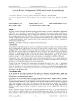
In order to inves gate the path-planning guideline we have proposed, we perform the test on a pick-and-place problem with the path de ne with 5 points as follow:
<small>Figure 9. Mark points of pick and place object application </small>In which detail of the procedure is shown below :
S (0.1, 0.6, 0.2) is the star ng point of robot A’ (0, 0.5, 0.2)
</div><span class="text_page_counter">Trang 26</span><div class="page_container" data-page="26">26 A (0, 0.5, 0.1)
B (0.5, 0, 0.1) B’ (0.5, 0, 0.2)
Procedure SA’ (1) A’A (2) Halt AA’ (3) A’B’ (4) B’B (5) Halt BB’ (6)
For this problem, we use Simulink and Matlab to solve the problem. First, we determine the joint variables combina on required at each mark point by inverse kinema cs.
<small>Figure . Simulink program for determine set of joint variables at mark point 10</small>
Next, build up the func on for joint variable, velocity, and accelera on for each procedure based on start value of joint variable, end value of joint variable, and me dura on to perform procedure. Then by subs tute a time signal to the func on, we obtain the path planning for the procedure. The Simulink to perform this task is:
</div><span class="text_page_counter">Trang 27</span><div class="page_container" data-page="27"><small>Figure . Trajectory planning block 11</small>The results obtained from the program are shown below:
<small>Figure . Joint variables versus time diagram 12</small>
</div><span class="text_page_counter">Trang 28</span><div class="page_container" data-page="28">28
<small>Figure . Joint velocity versus time diagram 13</small>
<small>Figure . Joint acceleration versus time diagram 14</small>
</div><span class="text_page_counter">Trang 29</span><div class="page_container" data-page="29">For checking the solu on, we can use forward kinema cs equa ons in order to construct again the path of robot during the pick and place process. This whole program can be connected and is done in Simulink as:
<small>Figure . Simulink program for path planning of SCARA robot with forward simulation 15</small>
By the procedure above, the nal result of the path for pick and place task of the robot is generated as follow:
<small>Figure . Theoretical working trajectory of the robot for the task in 3D coordinate 16</small>
</div><span class="text_page_counter">Trang 30</span><div class="page_container" data-page="30">30
<b>3.2.3. Design of third-order trajectory in task space: </b>
For this part, the requirement is design the robot to follow a straight line across 2 points A and B. The simplest method is to split the path to many small sec on to solve for the necessary angle similar to joint space. The quality of the path is higher when each sec on is ge ng smaller.
With the problem of pick-and-place similar to the previous part, we can separate the path to 50 consecu ve sec on to perform the designing. We show again the problem below:
<small>Figure 17. Mark points of pick and place object application </small>In which detail of the procedure is shown below:
S (0.1, 0.6, 0.2) is the star ng point of robot A’ (0, 0.5, 0.2)
A (0, 0.5, 0.1) B’ (0.5, 0, 0.2) B (0.5, 0, 0.1)
Procedure SA’ (1) A’A (2) Halt AA’ (3) A’B’ (4) B’B (5) Halt BB’ (6)
To design the trajectory for robot, we usually use the n-order polynomial approxima on method. The form being used in this project is the third-order polynomial with the characteris cs as: Simple for design, assure the con nuous of the velocity, and reduce the bumpy and glitch when robot is working.
Design the trajectory in task space with straight line path:
In general, the func on of a line goes through 2 points 𝑀(𝑥 , 𝑦 , 𝑧<sub>0</sub> <sub>0</sub> <sub>0</sub>) and 𝑁(𝑥<small>𝑒</small>, 𝑦<sub>𝑒</sub>, 𝑧 ) is: <sub>𝑒</sub>
<small>𝑦𝑒−𝑦0</small>=<small>𝑧−𝑧0</small>
</div>