Code Division Multiple Access CDMA pdf
Bạn đang xem bản rút gọn của tài liệu. Xem và tải ngay bản đầy đủ của tài liệu tại đây (6.46 MB, 192 trang )
P1: IML/FFX P2: IML/FFX QC: IML/FFX T1: IML
MOBK023-FM MOBK023-Buehrer.cls September 28, 2006 15:54
Code Division Multiple Access
(CDMA)
i
Simpo PDF Merge and Split Unregistered Version -
P1: IML/FFX P2: IML/FFX QC: IML/FFX T1: IML
MOBK023-FM MOBK023-Buehrer.cls September 28, 2006 15:54
Copyright © 2006 by Morgan & Claypool
All rights reserved. No part of this publication may be reproduced, stored in a retrieval system, or transmitted in
any form or by any means—electronic, mechanical, photocopy, recording, or any other except for brief quotations
in printed reviews, without the prior permission of the publisher.
Code Division Multiple Access (CDMA)
R. Michael Buehrer
www.morganclaypool.com
ISBN: 1598290401 paperback
ISBN: 9781598290400 paperback
ISBN: 159829041X ebook
ISBN: 9781598290417 ebook
DOI 10.2200/S00017ED1V01Y200508COM002
A Publication in the Morgan & Claypool Publishers series
SYNTHESIS LECTURES ON COMMUNICATIONS #2
Lecture #2
Series Editor: William Tranter, Virginia Tech
Series ISSN: 1932-1244 print
Series ISSN: 1932-1708 electronic
First Edition
10987654321
Printed in the United States of America
ii
Simpo PDF Merge and Split Unregistered Version -
P1: IML/FFX P2: IML/FFX QC: IML/FFX T1: IML
MOBK023-FM MOBK023-Buehrer.cls September 28, 2006 15:54
Code Division Multiple Access
(CDMA)
R. Michael Buehrer
Virginia Polytechnic Institute and State University,
Blacksburg, Virginia, USA
SYNTHESIS LECTURES ON COMMUNICATIONS #2
M
&C
Morgan
&
Claypool Publishers
iii
Simpo PDF Merge and Split Unregistered Version -
ABSTRACT
This book covers the basic aspects of Code Division Multiple Access or CDMA. It begins
with an introduction to the basic ideas behind fixed and random access systems in order to
demonstrate the difference between CDMA and the more widely understood TDMA,
FDMA or CSMA. Secondly, a review of basic spread spectrum techniques is presented which
are used in CDMA systems including direct sequence, frequency-hopping, and time-hopping
approaches. The basic concept of CDMA is presented, followed by the four basic principles
of CDMA systems that impact their performance: interference averaging, universal frequen-
cy reuse, soft handoff, and statistical multiplexing. The focus of the discussion will then shift
to applications. The most common application of CDMA currently is cellular systems. A
detailed discussion on cellular voice systems based on CDMA, specifically IS-95, is present-
ed. The capacity of such systems will be examined as well as performance enhancement tech-
niques such as coding and spatial filtering. Also discussed are Third Generation CDMA cel-
lular systems and how they differ from Second Generation systems. A second application of
CDMA that is covered is spread spectrum packet radio networks. Finally, there is an exami-
nation of multi-user detection and interference cancellation and how such techniques impact
CDMA networks. This book should be of interest and value to engineers, advanced students,
and researchers in communications.
KEYWORDS
CDMA, Multiple Access, Spread Spectrum, Multiuser Detection, TDMA, FDMA, Packet
Radio Networks
iv
Simpo PDF Merge and Split Unregistered Version -
P1: IML/FFX P2: IML/FFX QC: IML/FFX T1: IML
MOBK023-FM MOBK023-Buehrer.cls September 28, 2006 15:54
This book is dedicated to those who patiently waited for me to finish: My wife Andrea and
our children, Faith, JoHannah, Noah, Gabrielle and Ruth.
v
Simpo PDF Merge and Split Unregistered Version -
P1: IML/FFX P2: IML/FFX QC: IML/FFX T1: IML
MOBK023-FM MOBK023-Buehrer.cls September 28, 2006 15:54
vi
Contents
1. Multiuser Communications 1
1.1 Conflict-Free Medium Access Control 2
1.1.1 Time Division Multiple Access 3
1.1.2 Frequency Division Multiple Access 5
1.1.3 Code Division Multiple Access 6
1.1.4 Traffic Engineering and Trunking Efficiency 8
1.1.5 Frequency Reuse 9
1.2 Contention-Based Medium Access Control. 15
1.2.1 ALOHA 16
1.2.2 Carrier Sense Multiple Access and Carrier Sense Multiple
Access/Collision Avoidance . . . 16
1.2.3 Other Random Access Methods 19
1.3 Multiple Access with Spread Spectrum . . 21
1.4 Summary 22
2. Spread Spectrum Techniques for Code Division Multiple Access 23
2.1 Forms of Code Division Multiple Access 23
2.2 Direct Sequence Code Division Multiple Access 24
2.2.1 Power Spectral Density of Direct Sequence Spread Spectrum 27
2.2.2 Multiple Access 30
2.3 Frequency Hopping 35
2.3.1 Slow Versus Fast Hopping 38
2.3.2 Power Spectral Density of Frequency-Hopped
Spread Spectrum 39
2.3.3 Multiple Access 41
2.4 Time Hopping 43
2.5 Link Performance of Direct Sequence Spread Spectrum in Code
Division Multiple Access 45
2.5.1 Additive White Gaussian Noise 45
2.5.2 Multipath Fading Channels. . 46
2.5.3 Impact of Bandwidth. . . 54
Simpo PDF Merge and Split Unregistered Version -
P1: IML/FFX P2: IML/FFX QC: IML/FFX T1: IML
MOBK023-FM MOBK023-Buehrer.cls September 28, 2006 15:54
CONTENTS vii
2.6 Multiple Access Performance of Direct Sequence Code
Division Multiple Access 56
2.6.1 Gaussian Approximation 57
2.6.2 Improved Gaussian Approximation 64
2.7 Link Performance of Frequency-Hopped Spread Spectrum 64
2.8 Multiple Access Performance of Frequency-Hopped
Code Division Multiple Access 67
2.9 Summary 71
3. Cellular Code Division Multiple Access 73
3.1 Principles of Cellular Code Division Multiple Access 73
3.1.1 Interference Averaging 73
3.1.2 Frequency Reuse 77
3.1.3 Soft Hand-Off 79
3.1.4 Statistical Multiplexing. . . 82
3.2 Code Division Multiple Access System Overview 83
3.3 Capacity 85
3.3.1 Comparison of Multiple Access Capacity 85
3.3.2 Second-Order Analysis 87
3.3.3 Capacity–Coverage Trade-Off . 93
3.3.4 Erlang Capacity 95
3.4 Radio Resource Management 100
3.4.1 Power Control 100
3.4.2 Mobile-Assisted Soft Hand-Off 105
3.4.3 Admission Control 107
3.4.4 Load Control 109
3.5 Summary 110
4. Spread Spectrum Packet Radio Networks 111
4.1 Code Assignment Strategies 112
4.1.1 Common-Transmitter Protocol 112
4.1.2 Receiver-Transmitter Protocol 116
4.2 Channel Access Strategies 117
4.3 Direct Sequence Packet Radio Networks 118
4.4 Frequency-Hopped Packet Radio Networks 120
4.4.1 Perfect Side Information 121
4.4.2 No Side Information 124
4.5 Summary 124
Simpo PDF Merge and Split Unregistered Version -
P1: IML/FFX P2: IML/FFX QC: IML/FFX T1: IML
MOBK023-FM MOBK023-Buehrer.cls September 28, 2006 15:54
viii CONTENTS
5. Multiuser Detection 127
5.1 System Model 127
5.2 Optimal Multiuser Reception 129
5.3 Linear Sub-Optimal Multiuser Reception 131
5.3.1 The Decorrelating Detector . 132
5.3.2 Linear Minimum Mean Squared Error Receiver 137
5.4 Non-Linear Sub-Optimal Receivers: Decision Feedback 137
5.4.1 Decorrelating Decision Feedback 138
5.4.2 Successive Interference Cancellation 140
5.4.3 Parallel Interference Cancellation 147
5.4.4 Multistage Receivers 149
5.5 A Comparison of Sub-Optimal Multiuser Receivers 156
5.5.1 AWGN Channels 156
5.5.2 Near-Far Performance 157
5.5.3 Rayleigh Fading 160
5.5.4 Timing Estimation Errors . . 161
5.6 Application Example: IS-95 162
5.6.1 Parallel Interference Cancellation 165
5.6.2 Performance in an Additive White Gaussian Noise Channel 167
5.6.3 Multipath Fading and Rake Reception 168
5.6.4 Voice activity, power control, and coding 168
5.6.5 Out-of-Cell Interference 170
5.7 Summary 171
Simpo PDF Merge and Split Unregistered Version -
P1: IML/FFX P2: IML/FFX QC: IML/FFX T1: IML
MOBK023-FM MOBK023-Buehrer.cls September 28, 2006 15:54
ix
Preface
The objective of this book is to provide the reader with a concise introduction to the use
of spread spectrum waveforms in multiple user systems, often termed code division multiple
access or CDMA. The book has been an outgrowth of course notes presented in a graduate-
level course on spread spectrum communications. This book should provide sufficient material
to cover CDMA systems within a graduate-level course on spread spectrum, advanced digital
communication, or multiple access. The text should also be useful for working engineers who
desire a basic understanding of the fundamental concepts underlying CDMA.
The reader of this book is expected to have a fundamental understanding of digital com-
munications and some understanding of wireless systems in general. Additionally, readers are
assumed to be generally familiar with basic stochastic processes, detection theory, and commu-
nication theory. The book builds on these fundamentals by explaining how spread spectrum
systems differ from standard digital communication systems and, more importantly, how spread
spectrum waveforms can be used as a means of channelization in a multiple user scenario.
The book covers the basic aspects of CDMA. In Chapter 1, the basic ideas behind
conflict-free and contention-based systems are introduced to demonstrate the difference be-
tween CDMA and more widely understood orthogonal access techniques such as time division
multiple access and frequency division multiple access. Additionally, random access schemes
such as carrier sense multiple access are examined.
In Chapter 2, basic spread spectrum techniques that are used in CDMA systems are
reviewed, including direct sequence spread spectrum, frequency-hopped spread spectrum, and
time-hopping approaches. Both the link performance of such waveforms (in additive white
Gaussian noise channels and fading channels) as well as the multiple access performance are
examined. Special emphasis is given to fading channels since spread spectrum is more advanta-
geous in these channels.
Once the basic concept of CDMA is presented, Chapter 3 focuses on cellular CDMA
systems. Specifically, four basic principles of cellular CDMA systems are presented, and their
impact on the performance of CDMA is explained. These four basic concepts include interfer-
ence averaging, universal frequency reuse, soft hand-off, and statistical multiplexing. While the
discussion is general, the CDMA cellular standard IS-95 is often used as an example. Addi-
tionally, important CDMA system functions (often termed radio resource management tech-
niques),such aspowercontrol, mobile-assisted hand-off,loadcontrol, and admission control, are
Simpo PDF Merge and Split Unregistered Version -
P1: IML/FFX P2: IML/FFX QC: IML/FFX T1: IML
MOBK023-FM MOBK023-Buehrer.cls September 28, 2006 15:54
xPREFACE
examined. Finally, the capacity of CDMA cellular systems on both the uplink and downlink is
derived, emphasizing the differences between the links.
Spread spectrum waveforms are used not only in fixed access techniques such as in cellular
systems, but also for multiple access in packet radio networks (PRNs). Chapter 4 discusses
spread spectrum based PRNs emphasizing the differences between PRNs and their better
known cellular counterparts. A primary emphasis is on spreading code assignment techniques,
which is crucial in non-centralized systems.
Finally, Chapter 5 focuses on multiuser detection. A primary limitation of CDMA link
performance and system capacity is in-cell multiple access interference (MAI). Multiuser de-
tection is one means of mitigating MAI on the uplink of CDMA systems. The discussion of
multiuser detection algorithms is broken down into two basic categories: linear techniques and
non-linear techniques. Linear techniques discussed include the decorrelating detector and the
minimum mean square error detector. Among the non-linear approaches examined, parallel in-
terference cancellation and successive interference cancellation are the most prominent. Finally,
all these techniques are compared, the benefits and detriments of each approach are mentioned,
and the application of multiuser detection to the IS-95 cellular standard is examined.
I would like to acknowledge the many students who helped make this book possible.
First, I would like to thank all of the students who have taken my spread spectrum course for
their comments and input. I would also like to specifically thank several graduate students who
helped with various plots and simulations including (but certainly not limited to) Ihsan Akbar,
Dan Hibbard, Jihad Ibrahim, Nishant Kumar, Rekha Menon, and Swaroop Venkatesh as well
as former colleagues at Bell Labs, especially Steve Nicoloso and Rob Soni for their assistance
in Section 5.6. I also want to thank Lori Hughes for her many hours of editing that (or is it
“which”?) greatly improved the initial manuscript.
Simpo PDF Merge and Split Unregistered Version -
P1: IML/FFX P2: IML/FFX QC: IML/FFX T1: IML
MOBK023-01 MOBK023-Buehrer.cls September 28, 2006 15:54
1
CHAPTER 1
Multiuser Communications
All communication systems that support multiple users must have a set of protocols to allow
these multiple users to share a common access medium. This single-access medium may be
explicitly shared or broken up into smaller pieces, termed channels, that must also be shared.
A logical channel can be defined as some fraction of the available access medium that is used
by a particular transmit/receive pair. The system may contain only a single channel or tens of
channels. However, in either case, the number of possible transmit/receive pairs in the system
typically far outweighs the number of channels that are available. Thus, communication systems
must have some mechanism for sharing the available channels among active transmit/receive
pairs. This mechanism is termed multiple access control or sometimes medium access. Many meth-
ods exist for providing multiple access, and we will briefly examine the major techniques in
this chapter. However, the focus of this book is one specific multiple access technique termed
code division multiple access or CDMA, which is inherently associated with spread spectrum
communication techniques. Since spread spectrum was developed as a military technology,
CDMA techniques traditionally have been limited to military systems [1]. However, since the
early 1990s, CDMA has been heavily investigated for commercial systems. Of particular note is
the success that CDMA has experienced in commercial cellular systems. The first commercial
CDMA standard, IS-95, pioneered by Qualcomm, Inc., was one of the three major second
generation cellular standards and led to a third generation of cellular systems that was domi-
nated by CDMA techniques (at least for voice services). However, before we discuss CDMA
in detail, we must first discuss the more general concept of multiple access.
Two basic classes of multiple access are illustrated in Figure 1.1 [2]: contention-based
techniques and conflict-free techniques. Conflict-free multiple access involves some type of
reservation scheme in which theresources are divided into multiple channels. These channels are
then reserved (through some other mechanism) for use by transmit/receive pairs for the duration
of their communication. On the other hand, contention-based multiple access techniques allow
no reservation. Instead, users must contend for the system resources whenever communication
takes place. Such systems typically use the entire access medium as a single channel, although
multi-channel versions are certainly possible. Both types of systems have several variations and
Simpo PDF Merge and Split Unregistered Version -
P1: IML/FFX P2: IML/FFX QC: IML/FFX T1: IML
MOBK023-01 MOBK023-Buehrer.cls September 28, 2006 15:54
2 CODE DIVISION MULTIPLE ACCESS (CDMA)
Multiple access
techniques
Contention-based
Conflict-free
Random
access
Collision
resolution
TREE,
WINDOW,
etc.
TDMA,
CDMA,
FDMA,
Token Bus,
etc.
ALOHA,
CSMA,
CSMA/CA,
RTS/CTS,
etc.
FIGURE 1.1: Multiple access techniques.
provide benefits for different types of traffic. We will now discuss the two major classes of
multiple access.
1.1 CONFLICT-FREE MEDIUM ACCESS CONTROL
As mentioned previously, contention-free (or conflict-free) multiple access involves the division
of system resources (i.e., the access medium) into fixed channels, which are then reserved
by transmit/receive pairs for communication. In this way, users are guaranteed a channel for
the duration of their communication. This type of multiple access is particularly beneficial for
applications that require continuous, regular access toa channel, such asvoice or video. However,
for bursty data sources, such a scheme is inefficient because the channel is very often unused
while it is reserved. The main difference between the types of contention-free multiple access is
in how the channels are defined. In time division multiple access (TDMA), channels are defined
according to time slots. In frequency division multiple access (FDMA), channels are defined
according to frequency bands, and in CDMA, channels are defined not by time or frequency
but by a spread spectrum parameter known as a spreading code. We will briefly review each type.
Simpo PDF Merge and Split Unregistered Version -
P1: IML/FFX P2: IML/FFX QC: IML/FFX T1: IML
MOBK023-01 MOBK023-Buehrer.cls September 28, 2006 15:54
MULTIUSER COMMUNICATIONS 3
1.1.1 Time Division Multiple Access
TDMA systems define channels according to time slot. In other words, system time is defined as
a series ofrepeating, fixed-time intervals (often called frames) that are further divided into a fixed
number of smaller time periods called slots. When a transmit/receive pair is given permission
to communicate, it is assigned a specific time slot in which to do so. Every time frame, each
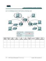
transmit/receive pair may communicate during its slot. An example is given in Figure 1.2 for
four time slots. Typically, all users are given an opportunity to transmit once during a frame.
Thus, the total frame is made up of K user slots and K guard times where K is the number
of transmitters actively accessing the medium or equivalently the number of channels. Guard
times are inserted to prevent collisions due to imperfect synchronization. The user throughput
is a function of the overall system transmission rate and the number of time slots available (i.e.,
the fraction of time they are permitted to transmit).
User
1
User
2
User
3
User
4
User
1
User
2
Time
User 1
User 2
User 3
User 4
R
x
Guard time
FIGURE 1.2: Example of a four-user TDMA system.
Simpo PDF Merge and Split Unregistered Version -
P1: IML/FFX P2: IML/FFX QC: IML/FFX T1: IML
MOBK023-01 MOBK023-Buehrer.cls September 28, 2006 15:54
4 CODE DIVISION MULTIPLE ACCESS (CDMA)
The example in Figure 1.2 demonstrates a centralized system in which multiple users
communicate to a single receiver.
1
A decentralized system can also use TDMA, but providing
strict time synchronization in a large, decentralized system can be very challenging. Additionally,
the example given shows only one side of the communication (mobile to base station) and
inherently assumes frequency division duplex (FDD) operation in which the channels from the
centralized transmitter to the distributed receivers occur on a different frequency channel. This
second band is also divided into time slots for transmission to the separate users. However,
TDMA systems can also use time division duplex (TDD) in which time is broken into two
consecutive frames; the first time frame is used for uplink (or downlink) transmission, and the
second time frame is used for downlink (or uplink) transmission.
In a pure TDMA system, each transmitter occupies the entire bandwidth when transmit-
ting. The system bit rate R
S
b
is the rate at which each user transmits when accessing the channel.
Ignoring guard times, the data rate per user is R
b
= (R
S
b
)/K, where K is the number of time
slots per frame. If guard times are included, the relationship is a little more complicated. The
time allocated per channel is simply equal to (T
f
/K) −T
g
where T
f
is the frame duration, K
is the number of time slots (i.e., channels), and T
g
is the guard time. The data rate per channel
is equal to the number of bits transmitted per user divided by the frame duration. Thus,
R
b
=
T
f
K
− T
g
R
S
b
T
f
=
R
S
b
K
−
T
g
T
f
R
S
b
(1.1)
Clearly, we wish to have a small guard time to improve the efficiency of the system. How-
ever, practical considerations limit the minimum size of T
g
. The bandwidth of the system is
proportional to the system data rate:
B
S
∝
R
S
b
k
α (1.2)
where k is the number of bits per symbol and α is a constant related to the filtering, pulse shape,
and modulation scheme.
There are advantages and disadvantages of TDMA as compared to other multiple ac-
cess schemes. One advantage of the scheme is that it requires only a single radio frequency/
intermediate frequency (RF/IF) section since all channels have the same frequency character-
istics. Another advantage of TDMA is the ease with which variable data rates and asymmetric
1
Note that the transmission from distributed users to a single receiver is typically referred to as the uplink while
transmission from the centralized transmitter to the distributed receivers is termed the downlink.
Simpo PDF Merge and Split Unregistered Version -
P1: IML/FFX P2: IML/FFX QC: IML/FFX T1: IML
MOBK023-01 MOBK023-Buehrer.cls September 28, 2006 15:54
MULTIUSER COMMUNICATIONS 5
links are accommodated. Variable data rates can be assigned by simply assigning multiple time
slots to a single transmit/receive pair. Asymmetric links can be accommodated by changing the
relative duration of uplink and downlink time slots. The relationship between the user-specific
data rate and the overall system data rate is further illustrated in the following example.
Example 1.1. A TDMA system is to be designed with ten channels and a guard time of 50μs.
If quadrature phase shift keying (QPSK) modulation is used, what system symbol rate is needed
to achieve a data rate of 200kbps with a frame duration 10ms?
Solution: The frame duration T
f
is 10ms. Due to guard time, the total time available for
transmission is 10ms − 10 ∗ 50μs = 9.5ms. The transmission time per channel is thus
9.5ms
10
= 0.95ms (1.3)
The required system data rate is then
R
S
b
=
10ms ∗ 200kbps
0.95ms
= 2.105Mbps (1.4)
Alternatively, from (1.1),
R
S
b
=
R
b
1
K
−
T
g
T
f
=
200 kbps
0.1 − 0.005
= 2.105 Mbps (1.5)
Using QPSK (two bits per symbol), the symbol rate needed is 2.105/2 = 1.05Msps.
1.1.2 Frequency Division Multiple Access
The second major type of contention-free multiple access is FDMA in which channels are
defined according to frequency allocation. Thus, all transmitters are active simultaneously but
occupy different segments of the RF spectrum as illustrated in Figure 1.3. In an FDMA system,
the bandwidth per user is simply related to the data rate and modulation scheme used. The total
bandwidth of the system is B
S
= K ∗ B where K is the number of channels and B = α(R
b
/k)
is the bandwidth per channel ignoring guard bands. With guard bands, we have
B
S
= K ∗
B + B
g
(1.6)
where B
g
is the size of the guard band.
The efficiency of TDMA and FDMA are essentially the same, with slight differences
depending on the guard times/bands required. Both techniques are referred to as orthogonal
Simpo PDF Merge and Split Unregistered Version -
P1: IML/FFX P2: IML/FFX QC: IML/FFX T1: IML
MOBK023-01 MOBK023-Buehrer.cls September 28, 2006 15:54
6 CODE DIVISION MULTIPLE ACCESS (CDMA)
FIGURE 1.3: Example of three-channel FDMA system.
multipleaccess techniquessince, ideally,thereis nointerferencebetween channels. An advantage
of FDMA over TDMA is the substantial reduction in the required symbol rate. Another
advantage of the FDMA is that no tight synchronism between users is required and strict
isolation between channels is relatively easy to maintain with properly designed filters and
tuners. However, disadvantages include the fact that with a larger number of channels the IF
filter (used to select the channel of interest) must be fairly narrow and allocating variable data
rates requires multiple receive filters.
1.1.3 Code Division Multiple Access
As we have seen from the previous two sections, a key to contention-free multiple access is the
definition of orthogonal channels. Orthogonal channels are channels in which a system user can
communicate without causing interference to another user. The orthogonality can be created
either in the time domain or in the frequency domain. In TDMA, users simply transmit at
different times, thus maintaining orthogonality in the time domain. In FDMA, users transmit
in different frequency bands, which creates orthogonality in the frequency domain since receivers
can filter out unwanted frequency bands. In reality, the channels in these access techniques are
Simpo PDF Merge and Split Unregistered Version -
P1: IML/FFX P2: IML/FFX QC: IML/FFX T1: IML
MOBK023-01 MOBK023-Buehrer.cls September 28, 2006 15:54
MULTIUSER COMMUNICATIONS 7
not truly orthogonal due to imperfect filters or imperfect time synchronization, but the cross-
channel interference is very small.
In CDMA systems, channels are defined not by time or frequency but by code. Spread
spectrum systems (as we will see in more detail in Chapter 2) rely on pseudo-random waveforms
termed spreading codes to create noise-like transmissions. If users can be given different codes
that have low cross-correlation properties, channels can be defined by those codes. To better
understand this, let us consider an FDMA system with two channels. Assuming a linear
modulation scheme, the transmit signals from two distinct users can be written as
s
1
(
t
)
=
2P
1
b
1
(
t
)
cos
(
ω
1
t + θ
1
)
(1.7a)
s
2
(
t
)
=
2P
2
b
2
(
t
)
cos
(
ω
2
t + θ
2
)
(1.7b)
where P
i
, b
i
(
t
)
, ω
i
, and θ
i
are the transmit power, data signal, transmit frequency, and random
phase offset for the ith user, respectively. Now consider the received signal (normalized so that
the desired signal is received at maximum power) at user 1:
r
1
(
t
)
= s
1
(
t
)
+
PL
R
s
2
(
t
)
+ n
(
t
)
(1.8)
where PL
R
is the relative path loss between transmitter 2 and receiver 1 and n
(
t
)
is additive
white Gaussian noise (AWGN). Now, assuming square pulses for simplicity, the output of the
matched filter receiver at user 1 for an arbitrary symbol period is
Z =
1
T
T
0
r
1
(
t
)
cos
(
ω
1
t + θ
1
)
dt (1.9)
where T is the data symbol period and we have examined the first symbol period. Provided
that
|
ω
1
− ω
2
|
T, the signal s
2
(t) will produce no response to the filter matched to signal
s
1
(t). Thus, we can say that the channels are orthogonal. We can write similar equations for
TDMA where the channels are defined by a time slot. However, in CDMA, the channels are
defined by spreading codes. For example, with direct sequence CDMA (DS-CDMA), the two
signals can be defined by
s
1
(t) =
2P
1
a
1
(
t
)
b
1
(t)cos
(
ω
1
t + θ
1
)
(1.10a)
s
2
(t) =
2P
2
a
2
(
t
)
b
2
(t)cos
(
ω
1
t + θ
2
)
(1.10b)
where a
1
(t) and a
2
(t) are spreading codes that define the “channel” for each user signal. Thus,
the cross-correlation between a
1
(t) and a
2
(t) dictates the performance of CDMA as we shall
see. In other words, we wish
ρ
12
=
1
T
T
0
a
1
(t)a
2
(
t
)
dt (1.11)
Simpo PDF Merge and Split Unregistered Version -
P1: IML/FFX P2: IML/FFX QC: IML/FFX T1: IML
MOBK023-01 MOBK023-Buehrer.cls September 28, 2006 15:54
8 CODE DIVISION MULTIPLE ACCESS (CDMA)
to be small to avoid excessive interference between users. In general, will be demonstrated
|ρ
ij
| > 0, ∀i = j, and thus, CDMA is a non-orthogonal multiple access scheme. However,
CDMA has other advantages as we shall see.
1.1.4 Traffic Engineering and Trunking Efficiency
The previous discussion focused on the number of channels supported by a specific system.
However, in most systems, the number of users that needs to be supported typically far exceeds
the number of channels available. However, since not all users of the system require the use of
a channel at the same time, a small number of channels can statistically support a large number
of users. This concept is known as trunking and exploits the statistical behavior of user access.
Determining the user population that can be supported by a number of channels is termed
traffic engineering or traffic analysis. Classic traffic analysis is based on voice applications and was
originally developed to determine the number of telephone circuits required to handle a given
number of telephones [3]. Clearly, due to the random nature of users accessing the system, some
probability exists such that the number of users requesting a channel will exceed the number of
channels available. When this happens, we say that an attempt to use the system is blocked.For
cellular voice systems, the probability that a user is blocked during the busiest hour of the day
is termed the grade of service (GOS).
The probability of blocking is determined using a queuing model for the system [4]. To
develop this queuing model, it is typically assumed that the time between user requests for
a channel is exponentially distributed (i.e., short times between consecutive requests are more
likely than very long times between consecutive requests). Such an assumption leads to a Poisson
distribution for the number of requests in a given time frame based on some average arrival rate
λ. It is further assumed that the service time (i.e., the length of time that the channel is required
by the user) is also exponentially distributed with an average service time 1/μ. Since there
is a finite number of channels K available, this scenario is modeled by the classic M/M/K/K
queue [4]. Since we further assume that blocked calls are cleared (as opposed to simply being
delayed for some amount of time), the probability of blocking is simply the probability that all
K channels are being used and is termed the Erlang B formula, which is given by
Pr{blocking}=
K
K!
K
k=0
k
k!
(1.12)
where = λ/μ is the offered traffic load in Erlangs. As an example, with K = 20 channels and
an offered load of = 13.2 Erlangs, the blocking probability is calculated as 2%. Assuming
that the average user traffic is 0.02 Erlangs/subscriber (i.e., each subscriber makes one 72-
second call per hour), the total number of subscribers that can be supported with a 2% blocking
probability is 13.2/0.02 = 660.
Simpo PDF Merge and Split Unregistered Version -
P1: IML/FFX P2: IML/FFX QC: IML/FFX T1: IML
MOBK023-01 MOBK023-Buehrer.cls September 28, 2006 15:54
MULTIUSER COMMUNICATIONS 9
Example 1.2. A specific service area has 850 subscribers. Assuming that the average user
traffic is 0.05 Erlangs/subscriber, determine the minimum number of channels necessary to
guarantee no worse than a 1% blocking probability. If the service area were doubled such that
1700 subscribers were supported (assuming a uniform user density), how many channels are
needed?
Solution: Given that there are 850 subscribers and 0.05 Erlangs/subscriber, the system must
support
= 850 ∗0.05
= 42.5 Erlangs (1.13)
We must thus solve (1.12) for K with = 42.5 and Pr{blocking}=0.01. This is simplified by
using an Erlang B table as provided in Appendix A. From Table A.1, we find that we require
K = 56 channels. If the number of subscribers were doubled ( = 85 Erlangs), we would
require K = 102 channels.
Note that in the preceding example, when doubling the number of subscribers supported,
the number of channels required does not double but increases by a factor of less than two.
This effect is known as trunking efficiency and is a general principle of queueing systems. By
increasing the pool of channels available by a factor of X, the number of subscribers supported
is increased by more than X due to the statistical nature of channel usage.
1.1.5 Frequency Reuse
Even with trunking efficiency, the number of channels required to cover a large metropolitan
area (e.g., in a cellular system) is quite large. For example, in a city of two million people with
a 10% market penetration rate, if a service provider has 20% market share, it must support
40,000 subscribers. Even if each subscriber generates only 0.02 Erlangs, the total system load is
800 Erlangs, leading to a large number of required channels. To deal with the large number of
required channels, frequency reuse is used in cellular systems as it is in many wireless systems,
including broadcast radio and television, wireless local area networks (WLANs), and public
safety radio networks. However, the frequency reuse concept gained most of its popularity
through its use in cellular systems, and it is illustrated in Figure 1.4. Because transmitted signal
power decays exponentially with distance, co-frequency channels (whether TDMA or FDMA)
can be reused in geographically separated locations. Typically, a set of K channels is divided
into Q sets where Q is the reuse factor and contiguous areas utilize one of the Q sets. A given
set of channels can be used in two areas if the areas are separated by sufficient distance to
ensure that two channels using the same time slot and/or frequency avoid interfering with each
other. Figure 1.4 demonstrates an example of a reuse factor of Q = 7. Note that a tessellation
Simpo PDF Merge and Split Unregistered Version -
P1: IML/FFX P2: IML/FFX QC: IML/FFX T1: IML
MOBK023-01 MOBK023-Buehrer.cls September 28, 2006 15:54
10 CODE DIVISION MULTIPLE ACCESS (CDMA)
1
3
5
4
5
4
7
2
6
6
3
5
7
3
4
2
6
7
2
1
1
1
1
1
1
7
6
5
2
3
4
6
5
7
FIGURE 1.4: Classic frequency reuse for a reuse pattern of 7.
of hexagons is used to cover the entire service area. This theoretical coverage pattern in which
individual geographic areas are called cells is the origination of the term cellular [5].
To ensure a minimum distance between co-frequency cells, only certain frequency reuse
patterns are possible. Specifically, Q = i
2
+ij + j
2
for any positive integers i and j [6]. With
such patterns, it can be shown that the minimum distance between co-frequency cells is D =
√
3Qd
r
where d
r
is the cell radius [6]. This distance along with the maximum interference
tolerable determines the allowable reuse factor.
The reuse of channels means that co-channel interference is received by each receiver
in the system. The reuse pattern used depends on the minimum signal-to-interference ratio
(SIR) that can be tolerated. The SIR experienced in a system depends on the geography of the
area, the building size and density, and other environmental factors as well as the reuse pattern.
However, for the sake of discussion, let us assume that the environment is uniform, all cells
have the same size, and the transmit power decays with d
κ
where d is the distance from the
transmitter to the receiver and κ is termed the exponential path loss factor. It can be shown that
Simpo PDF Merge and Split Unregistered Version -
P1: IML/FFX P2: IML/FFX QC: IML/FFX T1: IML
MOBK023-01 MOBK023-Buehrer.cls September 28, 2006 15:54
MULTIUSER COMMUNICATIONS 11
six cells are always in the first tier of co-channel cells as seen in Figure 1.4. If the interference
from the first tier dominates the interference, the SIR experienced can be calculated as
SIR =
P
r
6
k=1
I
k
(1.14)
where P
r
is the desired received signal power and I
k
is the received signal power from the kth
co-channel interferer. The worst SIR on the downlink will occur when the mobile is at the cell
edge, i.e., d = d
r
. It can be shown that the uplink (the link from the mobile to the base station)
and downlink (the link from the base station to the mobile) provide similar results, so we will
look only at the downlink. Thus, if P
t
is the transmit power at each base station, the SIR is
SIR =
P
t
d
κ
r
6
k=1
P
t
D
κ
k
=
d
−κ
r
6D
−κ
=
d
−κ
r
6
√
3Qd
r
−κ
=
√
3Q
κ
6
(1.15)
where D
k
is the distance of the kth interfering base station to the mobile of interest and we
use the approximation that D
k
≈ D, ∀k. Thus, we can see that an increase in Q provides an
improvement in SIR. However, for a fixed number of cells, increasing Q decreases the number
of channels available per cell. Thus, a trade-off exists between the required SIR and spectral
efficiency as shown in the following examples.
Example 1.3. Assuming a path loss factor of κ = 4, determine the maximum number of
channels per cell if there are 450 total channels available and the required SIR is 18dB. Does
the answer change if you include both the first and the second tier of co-channel interferers?
Solution: From (1.15), we have
10
1.8
≤
√
3Q
4
6
(1.16)
Rearranging, we have
Q ≥
√
6 ∗ 10
1.8
3
= 6.48 (1.17)
Simpo PDF Merge and Split Unregistered Version -
P1: IML/FFX P2: IML/FFX QC: IML/FFX T1: IML
MOBK023-01 MOBK023-Buehrer.cls September 28, 2006 15:54
12 CODE DIVISION MULTIPLE ACCESS (CDMA)
The smallest valid value of Q greater than 6.48 is then Q = 7
(
i = 2, j = 1
)
. Thus, the maxi-
mum number of allowable channels per cell is
K =
450
7
= 64 (1.18)
Now, if we include the second tier of interferers, we have
SIR =
P
t
d
κ
r
6
k=1
P
t
D
κ
k
+
12
k=7
P
t
D
κ
k
(1.19)
It can be shown that D
7
= D
8
=···=D
12
= 2D. Thus, we have
SIR =
d
−κ
r
6
√
3Qd
r
−κ
+ 6
2
√
3Qd
r
−κ
=
√
3Q
κ
6 + 6/2
κ
(1.20)
which leads to
Q =
6 + 6/2
4
∗ 10
1.8
3
= 6.68 (1.21)
Clearly, including the second tier of interferers makes no significant difference, and we are
justified in ignoring it.
Frequency reuse is heavily dependent on propagation conditions as well as the desired
SIR as we can see in the following example.
Example 1.4. Repeat Example 1.3 if the path loss factor is κ = 3.
Solution: Repeating the analysis from Example 1.3 with κ = 3, we have
Q =
6 ∗ 10
1.8
2/3
3
= 17.4 (1.22)
The smallest valid value of Q greater than 17.4 is Q = 19 (i = 3, j = 2), and the maximum
number of channels per cell is K = 23. Thus, we see that while a larger path loss factor means
that more power is required to cover a particular area (i.e., there is more path loss at a fixed
Simpo PDF Merge and Split Unregistered Version -
P1: IML/FFX P2: IML/FFX QC: IML/FFX T1: IML
MOBK023-01 MOBK023-Buehrer.cls September 28, 2006 15:54
MULTIUSER COMMUNICATIONS 13
distance), a larger path loss factor actually benefits capacity in a multi-cell scenario since greater
isolation between cells is experienced.
The previous example showed that the efficiency of frequency reuse improves as the
propagation conditions worsen. In the next example, we show that the efficiency is also heavily
dependent on the desired SIR. Thus, if the system can tolerate lower values of SIR, the overall
system efficiency can be improved.
Example 1.5. Repeat Example 1.3 if an SIR of 12dB can be tolerated.
Solution: If an SIR of 12dB can be supported, we have (assuming κ = 4),
Q =
√
6 ∗ 10
1.2
3
= 3.25 (1.23)
The smallest allowable value of Q greaterthan 3.25 is Q = 4, which provides K = 450/4 = 112
channels per cell. Thus, we clearly see that if we can tolerate lower SIR, we can increase our
capacity (i.e., the number of channels per cell).
It should be noted that frequency reuseis classically associated with FDMA. Theoretically,
there is no reason why pure TDMA cannot also employ reuse, although, practically speaking,
synchronization across multiple cells would pose a significant practical challenge. If systems
employ some combination of FDMA and TDMA, frequency bands can be divided according
to cells and reused as is done in second generation cellular systems based on the standards
IS-136 and Global System for Mobile Communications (GSM) [7]. CDMA, however, does
not typically employ reuse patterns. In fact, the use of universal frequency reuse (i.e., a reuse
pattern of 1) is a significant advantage of CDMA as we will discuss in detail in Chapter 3. To
demonstrate the difference between the interference statistics of FDMA and CDMA systems,
consider a TDMA/FDMA system with a reuse factor of Q = 7. As mentioned previously, the
average path loss with distance in a wireless system can be written as
PL∝ d
κ
(1.24)
However, because of terrain and various buildings in the environment, path loss versus
distance is typically found to be a log-normal random variable where the mean path loss is given
as in (1.24) and the standard deviation is between 6 and 10dB [7]. This variation is termed
shadowing. Thus, the SIR experienced on a particular link is a random variable depending on
the location of the various mobiles and the shadowing experienced by each. Specifically, the
Simpo PDF Merge and Split Unregistered Version -
P1: IML/FFX P2: IML/FFX QC: IML/FFX T1: IML
MOBK023-01 MOBK023-Buehrer.cls September 28, 2006 15:54
14 CODE DIVISION MULTIPLE ACCESS (CDMA)
SIR including log-normal shadowing can be written as
SIR =
P
r
6
k=1
I
k
(1.25)
where P
r
and I
k
are log-normal random variables. If we assume that the system uses power
control such that every uplink signal is received at its base station with the same power P, the
SIR for an FDMA system can be rewritten as
SIR =
P
6
k=1
P
d
k
D
k
κ
10
(
l
k
−l
k
)
/10
=
1
6
k=1
d
k
D
k
κ
10
(
l
k
−l
k
)
/10
(1.26)
where d
k
and D
k
are the distances from the kth co-channel interferer to the base station that it
is communicating with and the base station of interest, respectively, and l
k
and l
k
are the log-
normal shadowing factors from the kth co-channel interferer to its base station and the base
station of interest, respectively. On the other hand, with power control, the SIR for a CDMA
system can be written as
SIR =
N
(
K − 1
)
+
6K
k=1
f
d
k
D
k
κ
10
(
l
k
−l
k
)
/10
(1.27)
where N is the spreading gain (i.e., the ratio of the bandwidth to the data rate), K is the number
of users per cell, and f
(
x
)
is a function that guarantees that users are associated with the base
station having the smallest path loss. That is,
f
(
x
)
=
x 0 ≤ x ≤ 1
0 otherwise
(1.28)
The details of the CDMA SIR equation will be derived in Chapter 3. For now, we simply
use (1.27) to compare the SIR statistics for the two cases. Note that for CDMA systems, Q = 1
and thus D
k
=
√
3d
r
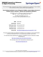
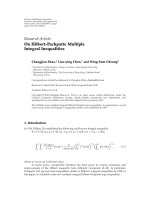
. A set of 10,000 random scenarios was simulated for uniformly distributed
users, and the empirical cumulative distribution functions (CDFs) are plotted in Figure 1.5
where the number of users K in the CDMA system was adjusted to achieve the same average
SIR. We can see that for the same average SIR, the distributions are very different. Specifically,
Simpo PDF Merge and Split Unregistered Version -
P1: IML/FFX P2: IML/FFX QC: IML/FFX T1: IML
MOBK023-01 MOBK023-Buehrer.cls September 28, 2006 15:54
MULTIUSER COMMUNICATIONS 15
0 5 10 15 20 25 30 35 40 45 50
0
0.1
0.2
0.3
0.4
0.5
0.6
0.7
0.8
0.9
1
SIR
Probability that
SIR
> abcissa
TDMA
CDMA
FIGURE 1.5: Empirical CDFs of SIR for FDMA and CDMA systems (both normalized to give an
average SIR of 12dB).
the CDMA system exhibits very little spread in the SIR value compared to the FDMA system.
This can be seen from the steep slope of the CDMA CDF plot. Since communication system
performance depends on the tails of the SIR (or signal-to-noise ratio, SNR) distribution, the
heavy tails of the SIR distribution in the FDMA case mean that the average SIR must be
significantly higher to achieve the same 90% value. We will examine this more thoroughly in
Chapter 3.
1.2 CONTENTION-BASED MEDIUM ACCESS CONTROL
Contention-free multiple access techniques are efficient provided that traffic is relatively con-
tinuous. If traffic is bursty, contention-free systems waste channels by dedicating them to a
single transmit/receive pair. Instead, systems with bursty traffic typically use contention-based
multiple access schemes. In contention-based schemes, the entire resource is dedicated to a
single channel and all users must contend to use the channel when they need to transmit.
Simpo PDF Merge and Split Unregistered Version -