Introduction to Fracture Mechanics pdf
Bạn đang xem bản rút gọn của tài liệu. Xem và tải ngay bản đầy đủ của tài liệu tại đây (1.45 MB, 56 trang )
Introduction to Fracture Mechanics
1
Introduction to Fracture Mechanics
From Suresh: Fatigue of Materials
Simpo PDF Merge and Split Unregistered Version -
INTRODUCTION
Importance of Fracture Mechanics :
All real materials contain defects: understand
the influence of these defects on the strength of
the material.
Defect
-
tolerant design
philosophy.
2
the material.
Defect
-
tolerant design
philosophy.
Relevance for Fatigue: understand the initiation
and growth of fatigue cracks.
We will use two approaches, an energy-based
approach and a more rigorous mechanics approach.
Simpo PDF Merge and Split Unregistered Version -
Key Idea : Griffith (1921) postulated that for unit
crack extension to occur under the influence of the
applied stress, the
decrease
in potential energy of
Griffith Fracture Theory
Introduction
3
applied stress, the
decrease
in potential energy of
the system, by virtue of the displacement of the
outer boundaries and the change in the stored elastic
energy, must equal the
increase in surface energy
due to crack extension.
Simpo PDF Merge and Split Unregistered Version -
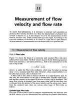
Consider the center-cracked plate shown below.
The in-plane dimensions of the plate are large
compared to the crack length.
4
Simpo PDF Merge and Split Unregistered Version -
Using the results of Inglis (1913) Griffith found that
the net change in potential energy of the plate caused
by the introduction of the crack is:
.
'
22
E
Ba
W
P
'
E
E
5
= E Plane stress
The surface energy of the crack system is
2
1
'
v
E
E
sS
aBW
4
Plane strain
where γ
S
is the free surface energy per unit surface area.
Simpo PDF Merge and Split Unregistered Version -
The total system energy is then given by
.4
'
22
SSP
aB
E
Ba
WWU
6
Griffith noted that the critical condition for the onset
of crack growth is:
,02
'
2
S
S
P
E
a
dA
dW
dA
dW
dA
dU
Simpo PDF Merge and Split Unregistered Version -
where A=2aB is the crack area and dA denotes an
incremental increase in the crack area.
Thus the stress required to initiate fracture is:
.
'2
a
E
S
f
7
a
As the second derivative, d
2
U/da
2
is negative, the
above equilibrium condition gives rise to
unstable
crack propagation. This applies for brittle materials;
it must be modified for ductile materials such as metals.
Simpo PDF Merge and Split Unregistered Version -
Orowan (1952) extended Griffith’s brittle fracture
concept to metals by simply adding a term representing
plastic energy dissipation. The resultant expression
for fracture initiation is
,
)('2E
p
s
8
,
a
p
s
f
where is the plastic work per unit area of surface
created. Generally is much larger than
p
.
s
p
Simpo PDF Merge and Split Unregistered Version -
Energy Release Rate
Crack Driving Force
Consider an elastic plate with an edge crack of length
as shown below:
,
a
9
Simpo PDF Merge and Split Unregistered Version -
The total mechanical potential energy of a cracked
elastic body is given by the general expression
FP
wW
where is the stored elastic strain energy and is
F
w
10
the work done by the external forces.
F
Irwin (1956) proposed an approach for the
characterization of the driving force for fracture in
cracked bodies, which is conceptually equivalent to
that of the Griffith model.
Simpo PDF Merge and Split Unregistered Version -
Irwin introduced, for this purpose, the energy release
rate
G which is defined as
.
d
dW
P
W
P
, and thus
G
, can be evaluated for different loading
G
11
W
P
, and thus
G
, can be evaluated for different loading
conditions. This definition is valid for both linear and
nonlinear elastic deformation of the body.
G
is a function
of the load (or displacement) and crack length. It is
independent of the boundary conditions, in particular
whether the loading is fixed-displacement or fixed-load.
Simpo PDF Merge and Split Unregistered Version -
The Griffith criterion for fracture initiation in an ideally
brittle solid can be re-phrased in terms of
G such that
.2
'
2
S
a
We define the compliance C (inverse of the stiffness) of
G
12
a cracked solid as C=u / F. It can be shown that
.
2
2
da
dC
B
F
Thus measurements of compliance as a function of crack
length allow the energy release rate to be evaluated.
G
Simpo PDF Merge and Split Unregistered Version -
Modes of Fracture
The three basic modes of separation of the crack
surfaces (
modes of fracture) are depicted below:
13
Combinations of modes (mixed-mode loading) are
also possible.
Simpo PDF Merge and Split Unregistered Version -
Modes of Fracture
Definitions
Mode I (tensile opening mode): The crack faces
separate in a direction normal to the plane of the crack.
The displacements are symmetric with respect to
the
x – z and x – y planes.
14
Mode II (in-plane sliding mode): The crack faces
are mutually sheared in a direction normal to the
crack front. The displacements are symmetric with
respect to the
x – y plane and anti-symmetric with
respect to the
x – z plane.
Simpo PDF Merge and Split Unregistered Version -
Modes of Fracture
Definitions
Mode III (tearing or anti-plane shear mode): The
crack faces are sheared parallel to the crack front.
The displacements are antisymmetric with respect
to the
x
–
y
and
x
–
z
planes.
15
to the
x
–
y
and
x
–
z
planes.
The crack face displacements in modes II and III
find an analogy to the motion of edge dislocations
and screw dislocations, respectively.
Simpo PDF Merge and Split Unregistered Version -
Plane Crack Problem
The preceding analysis considered fracture from an
energy standpoint. We now carry out a linear elastic
stress analysis of the cracked body, which will
allow us to formulate critical conditions for the
16
allow us to formulate critical conditions for the
growth of flaws more precisely. An analysis of this
type falls within the field of
Linear Elastic
Fracture Mechanics
(LEFM).
Simpo PDF Merge and Split Unregistered Version -
We consider a semi-infinite crack in an infinite plate
of an isotropic and homogeneous solid as shown below:
17
Our goal is to develop expressions for the stresses,
strains and displacements around the crack tip.
Simpo PDF Merge and Split Unregistered Version -
Plane Crack Problem
Equilibrium Equations
The equilibrium equations (no body forces) are
,0
1
rrr
rrr
rr
18
,0
2
1
rrr
rr
where and are the polar coordinates as shown
previously.
r
Simpo PDF Merge and Split Unregistered Version -
Plane Crack Problem
Strain-Displacement
The strain-displacement relations for polar coordinates
are:
.
1
1
u
u
u
r
,
1
,
u
r
r
u
r
u
rr
rr
19
.
1
2
1
r
u
r
u
u
r
r
r
The strain compatibility equation in polar coordinates is:
.0
11112
2
2
22
2
2
2
rrrrrrrrr
rrrr
rr
Simpo PDF Merge and Split Unregistered Version -
Plane Crack Problem
Hooke’s Law
Hooke’s Law (for plane stress, ):
0
zz
,
rr
E
,
rrrr
E
.
2
G
G
20
For the case of plane strain ( ):
0
zz
,12
rrrr
G
.
2
rrr
G
G
,12
rr
G
.2
rr
G
Simpo PDF Merge and Split Unregistered Version -
Plane Crack Problem
Airy Stress Function
For the plane problem, the equations of equilibrium are
satisfied when the stress components are expressed by
the
Airy stress function through
x
,
,
11
22
xxx
rr
21
,
,
222
r
r
rr
rr
.
1
x
rr
r
Using these definitions for the stresses and Hooke’s
law, the strains can be expressed in terms of .
x
Simpo PDF Merge and Split Unregistered Version -
It can be shown that the compatibility equation, when
expressed in terms of the Airy stress function, satisfies
the biharmonic equation:
.
11
,0
2
2
22
2
222
rrrr
The boundary conditions for this plane crack problem
22
The boundary conditions for this plane crack problem
are: for
0
r
.
These conditions express the fact that the crack is
traction-free (no loads applied to crack face).
Note: there is no condition on .
rr
Simpo PDF Merge and Split Unregistered Version -
A choice of the Airy stress function for the present
crack problem should be such that
x has a singularity
at the crack tip, and is single-valued. We try a solution
of the form:
,,,
2
rqrpr
23
Where p and p are harmonic functions of r and θ
(i.e. and
0
2
p
).0
2
q
Now consider a separate solution, of
the following form (Williams, 1957):
,
rR
Simpo PDF Merge and Split Unregistered Version -
,sincos
21
rArAp
.2sin2cos
2
2
2
1
rBrBq
This form leads to the following expression for x:
2coscos
11
2
BArx
.
2
sin
sin
2
B
A
r
24
.
2
sin
sin
22
2
B
A
r
Note that we have expressed x as a symmetric part and
an anti-symmetric part. The symmetric part provides
the
Mode I solution while the anti-symmetric part
provides the
Mode II solution. We will derive the
Mode I solution here.
Simpo PDF Merge and Split Unregistered Version -
2
2
r
2coscos12
11
BAr
rx
rr
r
1
25
2sin2sin1
11
BAr
Apply the boundary conditions:
,0cos
11
BA
.0sin2
11
BA
Simpo PDF Merge and Split Unregistered Version -