NAVY UNDERWATER CUTTING & WELDING MANUALDISTRIBUTION potx
Bạn đang xem bản rút gọn của tài liệu. Xem và tải ngay bản đầy đủ của tài liệu tại đây (2.38 MB, 200 trang )
U.S. NAVY
UNDERWATER
CUTTING & WELDING
MANUAL
S0300-BB-MAN-010
0910-LP-111-3300
1 APRIL 1989
Change A Dated 15 September 1995
PUBLISHED BY DIRECTION OF COMMANDER, NAVAL SEA SYSTEMS COMMAND
DISTRIBUTION STATEMENT A:
THIS DOCUMENT HAS BEEN APPROVED FOR PUBLIC RELEASE
AND SALE; ITS DISTRIBUTION IS UNLIMITED.
THIS DOCUMENT SUPERSEDES NAVSHIPS 0929-LP-000-8010
Change B Dated 1 June 2002
A Change B
Page No.* Change No.
Title and A . . . . . . . . . . . . . . . . . . . . . . . . . . B
Certification Sheet . . . . . . . . . . . . . . . . . . . . B
blank . . . . . . . . . . . . . . . . . . . . . . . . . . . . . . . O
Change Record . . . . . . . . . . . . . . . . . . . . . . . O
Change Record-2 blank . . . . . . . . . . . . . . . . O
i . . . . . . . . . . . . . . . . . . . . . . . . . . . . . . . . . . . O
ii blank . . . . . . . . . . . . . . . . . . . . . . . . . . . . . O
iii . . . . . . . . . . . . . . . . . . . . . . . . . . . . . . . . . . A
iv . . . . . . . . . . . . . . . . . . . . . . . . . . . . . . . . . . B
v through viii. . . . . . . . . . . . . . . . . . . . . . . . . O
ix . . . . . . . . . . . . . . . . . . . . . . . . . . . . . . . . . . B
x through xiii. . . . . . . . . . . . . . . . . . . . . . . . . O
xiv blank . . . . . . . . . . . . . . . . . . . . . . . . . . . . O
xv through xxiii. . . . . . . . . . . . . . . . . . . . . . . A
xxiv blank . . . . . . . . . . . . . . . . . . . . . . . . . . . A
1-1 . . . . . . . . . . . . . . . . . . . . . . . . . . . . . . . . . O
1-2 . . . . . . . . . . . . . . . . . . . . . . . . . . . . . . . . . B
1-3 . . . . . . . . . . . . . . . . . . . . . . . . . . . . . . . . . O
1-4 blank . . . . . . . . . . . . . . . . . . . . . . . . . . . . O
Page No * Change No.
2-1 through 2-32 . . . . . . . . . . . . . . . . . . . . . .O
2-33 through 2-36 . . . . . . . . . . . . . . . . . . . . . B
2-37 through 2-38 . . . . . . . . . . . . . . . . . . . . .O
2-39 through 2-40 . . . . . . . . . . . . . . . . . . . . .A
2-41 through 2-47 . . . . . . . . . . . . . . . . . . . . .O
2-48 blank . . . . . . . . . . . . . . . . . . . . . . . . . . .O
3-1 through 3-26 . . . . . . . . . . . . . . . . . . . . . .O
4-1 through 4-29 . . . . . . . . . . . . . . . . . . . . . .O
4-30 . . . . . . . . . . . . . . . . . . . . . . . . . . . . . . . . B
A-1 through A-2. . . . . . . . . . . . . . . . . . . . . . .O
B-1 through B-2 . . . . . . . . . . . . . . . . . . . . . . .O
C-1 . . . . . . . . . . . . . . . . . . . . . . . . . . . . . . . . .O
C-2 blank . . . . . . . . . . . . . . . . . . . . . . . . . . . .O
D-1 through D-14. . . . . . . . . . . . . . . . . . . . . .A
E-1 through E-28 . . . . . . . . . . . . . . . . . . . . . .O
Glossary-1 through Glossary-4 . . . . . . . . . . .O
Index-1 . . . . . . . . . . . . . . . . . . . . . . . . . . . . . . B
Index-2 through Index-4 . . . . . . . . . . . . . . . .A
LIST OF EFFECTIVE PAGES
* 0 in this column indicates an original page.
Date of Original Pages is: 1 April 1989
Date of Change A Pages is: 15 September 1995
Date of Change B Pages is: 1 June 2002
S0300-BB-MAN-010
DEPARTMENT OF THE NAVY
NAVAL SEA SYSTEMS COMMAND
WASHINGTON, D.C. 20362
NAVSEA S0300-BB-MAN-010 0910-LP-111-3301
U.S. NAVY UNDERWATER CUTTING & WELDING MANUAL CHANGE B
1 June 2002
PUBLISHED BY DIRECTION OF
COMMANDER, NAVAL SEA SYSTEMS COMMAND
NAVSEA S0300-BB-MAN-010 is changed as follows:
1. Remove old pages and insert new pages as indicated in instruction below. Dispose of super-
seded pages in accordance with applicable regulations.
2. New or changed material is indicated by a vertical bar in the margin of the page.
After the attached enclosures have been inserted, record this CHANGE on the Record of Changes
sheet and insert this page behind the Title page.
Request for additional copies of this CHANGE shall be submitted to Commanding Officer, Naval
Publications and Form Center, 5801 Tabor Avenue, Philadelphia, PA 19120-5099.
CHANGE INSTRUCTIONS
SHEET 1 OF 1
REMOVE PAGES INSERT PAGES
TITLE AND A TITLE AND A
CERT SHEET CERT SHEET
iv iv
ix ix
1-2 1-2
2-33 through 2-36 2-33 through 2-36
4-30 4-30
Index-1 Index-1
S0300-BB-MAN-010
CHANGE
NO.
A 15 Sep 1998 KLBChangesaffectfrontmatter,Chapter2andAppendixD
DATE
OF
CHANGE
ENTERED
BY
TITLEAND/ORBRIEFDESCRIPTION
B
1 Jun 2002
Changes to Kerie Cable Thermal Arc Cutting System
FSL
S0300-BB-MAN-010
i (ii blank)
FOREWORD
Ship Salvage, Harbor Clearance and Wreck Removal oftentimes require extensive underwater
cutting and welding. The lack of recent fleet experience in these areas dictates the need for a man-
ual that incorporates state of the art equipment and tried and proven underwater cutting and weld-
ing techniques. The knowledge contained in this manual is a collection of fleet and commercial
experience. It has been reviewed by technical experts with extensive salvage and underwater cut-
ting and welding experience.
This revision of the Underwater Cutting and Welding Manual has been prepared to provide the
most current information on equipment and procedures available. All of the equipment covered
may not be found on the Diving Equipment Authorized for Navy Use (ANU) list (NAVSEAINST
10560.2), but is included in this manual as an aid to the salvor who finds himself in a “must get
the job done” situation. Further guidance can be found in Appendix E.
Due to limited time allocation, there is a lack of realistic underwater cutting and welding training
in the Navy’s diving schools. Students are given only the basics in school and thereafter must
practice to become proficient and gain the experience necessary to become “qualified underwater
cutters and welders.” I therefore charge all diving officers, master divers and diving supervisors to
establish or maintain existing training programs for underwater cutting and welding. Practice,
practice, practice.
C.A. BARTHOLOMEW
Director of Ocean Engineering
Supervisor of Salvage and Diving, USN
S0300-BB-MAN-010
Change A iii
FOREWARD i
TABLE OF CONTENTS iii
LIST OF ILLUSTRATIONS ix
LIST OF TABLES xi
STANDARD NAVY SYNTAX SUMMARY xiii
SAFETY SUMMARY xv
1 INTRODUCTION
1-1 SCOPE 1-1
1-2 UNDERWATER CUTTING OVERVIEW 1-1
1-3 UNDERWATER WELDING OVERVIEW 1-2
2 UNDERWATER CUTTING
2-1 INTRODUCTION 2-1
2-2 OXYGEN-ARC CUTTING 2-2
2-2.1 Principles of Operation 2-2
2-2.2 Steel-Tubular Electrodes 2-2
2-2.2.1 Advantages of the Steel-Tubular Electrodes 2-5
2-2.2.2 Disadvantages of the Steel-Tubular Electrode 2-5
2-2.3 Electrode Amperage Requirements 2-5
2-2.4 Oxygen Requirements 2-6
2-2.5 Material Consumption 2-6
2-2.6 Oxygen Pressure 2-6
2-2.7 Oxygen Purity 2-11
2-2.8 Grounding the Work 2-11
2-2.9 Steel-Tubular Electrode Cutting Technique (Thick plate) 2-11
2-2.10 Steel-Tubular Electrode Cutting Technique (Thin plate) 2-15
2-2.11 Piercing Holes in Steel Plate 2-15
2-2.12 Steel-Tubular Electrode Cutting Technique (Cast Iron and Non-Ferrous
Metals) 2-18
2-2.13 Post-dive Maintenance 2-18
2-3 EXOTHERMIC ELECTRODES 2-22
2-3.1 Electrode Amperage Requirements 2-22
2-3.2 Oxygen Requirements 2-25
2-3.3 Material Consumption 2-25
2-3.4 Advantages and Disadvantages of the Exothermic Electrode Cutting
Process 2-25
2-3.4.1 Disadvantages of Exothermic Electrodes 2-27
2-3.5 Grounding the Work 2-27
TABLE OF CONTENTS
Chapter/Paragraph Page
S0300-BB-MAN-010
iv Change B
2-3.6 Exothermic Cutting Technique 2-28
2-3.6.1 Exothermic Cutting Technique (Cast Iron, Stainless Steel and
Non-Ferrous Metals) 2-30
2-3.6.2 Exothermic Cutting Technique (Concrete, Rock and other
Non-Conductive Materials) 2-31
2-3.6.3 Exothermic Hole Piercing 2-31
2-3.7 Trouble Shooting 2-31
2-3.7.1 Symptoms 2-31
2-3.7.2 Probable Causes 2-32
2-3.7.3 Locating and Solving the Problem 2-32
2-3.8 Post-Dive Maintenance 2-33
2-4 SEELER ENTERPRISES LU-001 EXOTHERMIC
CUTTING TOOL (KERIE CABLE) 2-33
2-4.1 Advantages and Disadvantages of the of the Kerie Cable 2-34
2-4.2 Materials Required for Kerie Cable Cutting 2-35
2-4.3 Equipment Set-up 2-37
2-4.4 Kerie Cable Preparation 2-39
2-4.5 Cutting Underwater 2-39
2-4.6 Cutting Technique 2-40
2-4.7 Cutting Thin Metals 2-40
2-4.8 Cutting Thick Metals 2-41
2-4.9 Re-Lighting Cable Underwater 2-43
2-4.10 Emergency Off Safety Procedures 2-43
2-4.11 Loss of Communications 2-43
2-4.12 Equipment Tender 2-43
2-4.13 Electrical Precautions 2-43
2-4.14 Post-Dive Maintenance 2-43
2-5 SHIELDED METAL ARC CUTTING 2-44
2-5.1 Principles of Operation 2-44
2-5.2 Materials 2-44
2-5.3 Waterproofing Electrodes 2-44
2-5.4 Underwater Shielded Metal-Arc Cutting Techniques 2-45
2-5.5 Drag Technique 2-46
2-6 CONCLUSION 2-46
3 UNDERWATER WELDING
3-1 INTRODUCTION 3-1
3-2 MECHANICAL BARRIERS 3-2
3-2.1 Cofferdams and Caissons 3-2
3-2.2 Mini-Habitats 3-2
3-3 SHIELDED METAL-ARC WELDING 3-3
3-4 WET WELDING 3-3
3-5 SHIPBUILDING MATERIALS 3-3
S0300-BB-MAN-010
Change A v
3-6 MATERIALS USED IN UNDERWATER SHIELDED METAL-ARC
WELDING 3-6
3-6.1 Underwater Shielded Metal-Arc Welding Electrodes 3-6
3-6.2 Tong Test Ammeter 3-6
3-6.3 Electrode Polarity 3-6
3-7 UNDERWATER WELDING ARCS 3-8
3-8 CONDITIONS ADVERSE TO UNDERWATER WELDING 3-8
3-9 STRENGTH OF UNDERWATER FILLET WELDS 3-10
3-9.1 Parts of a Weld (Definitions) 3-10
3-9.2 Fillet Weld 3-12
3-9.3 Trial Weld 3-12
3-10 SURFACE CLEANING 3-12
3-11 JOINT FIT-UP 3-13
3-12 UNDERWATER SHIELDED METAL-ARC WELDING
TECHNIQUES 3-13
3-12.1 Welding Set-Up Procedures 3-13
3-12.2 Self-Consuming Technique 3-14
3-12.3 Fillet Welding in the Horizontal Position (Self-Consuming Technique) 3-14
3-12.3.1 Fillet Welding in the Vertical Position 3-17
3-12.3.2 Fillet Welding in the Overhead Position 3-17
3-12.3.3 Self-Consuming and Manipulative Techniques 3-20
3-12.3.4 Fillet Welding Where There is Poor Fit-Up 3-20
3-12.4 Welding on Thin Plates 3-20
3-13 PROCEDURE FOR REPAIRING SMALL CRACKS 3-22
3-13.1 Using a Rectangular Patch 3-22
3-13.2 Using a Circular Patch 3-22
3-14 POST-DIVE MAINTENANCE 3-25
4 UNDERWATER ARC CUTTING AND WELDING EQUIPMENT
4-1 INTRODUCTION 4-1
4-2 EQUIPMENT USED FOR UNDERWATER ARC CUTTING
AND WELDING 4-1
4-2.1 Oxygen-Arc and Shielded Metal-Arc Equipment 4-1
4-2.2 Diving Equipment 4-1
4-2.2.1 Welding Shields 4-1
4-2.3 Power Supply Requirements 4-9
4-2.3.1 Power Converters 4-9
4-2.3.2 Welding Generator, Pre-Setup Inspection 4-11
4-2.3.3 Polarity 4-11
4-2.3.4 Polarity test 4-11
4-2.3.5 Tong Test Ammeter 4-13
4-2.3.6 Amperage and Voltage 4-13
4-2.3.7 Diesel Driven Welding Generator Amperage and Voltage Settings 4-15
S0300-BB-MAN-010
vi Change A
4-2.4 Safety Switches 4-16
4-2.5 Power Cables and Connectors 4-16
4-2.6 Gas Manifolds 4-17
4-2.7 Underwater Oxygen-Arc Cutting Torches 4-17
4-3 EQUIPMENT FOR UNDERWATER SHIELDED METAL-ARC
WELDING 4-19
4-3.1 Electrode Holders 4-19
4-4 WELDING ACCESSORIES 4-20
Appendix Page
A DOCUMENTATION MATRIX
A-1 PURPOSE A-1
A-2 REFERENCE DOCUMENTS A-1
B METRIC CONVERSION FACTORS
English and Metric Equivalents B-1
Weights B-2
Measures B-2
Pressure or Stress (Force/Area) B-3
Temperature Conversion B-3
Metric Prefixes B-3
Multiplication Factors B-3
C BIBLIOGRAPHY C-1
D SAFETY IN UNDERWATER CUTTING AND WELDING
D-1 PURPOSE D-1
D-2 GENERAL D-1
D-3 EXPLOSIVE GASES D-1
D-3.1 General Information D-2
D-3.2 Specific Information D-2
D-4 ELECTRICITY UNDERWATER D-4
D-5 GENERAL PRECAUTIONS FOR UNDERWATER CUTTING AND
WELDING D-4
D-6 POWER SUPPLY D-5
D-7 ELECTRODE HOLDERS AND CUTTING TORCHES D-6
D-8 POWER CABLES AND CONNECTORS D-7
D-9 SAFETY SWITCH D-8
S0300-BB-MAN-010
Change A vii
D-10 FIRE AND EXPLOSION PREVENTION D-9
D-10.1 Major Causes D-10
D-11 COMPRESSED GAS SUPPLIES D-10
D-11.1 Use, Handling and Storage of Compressed Gases D-10
D-11.1.1 The Never List D-10
D-11.1.2 The Always List D-11
D-11.1.3 General Oxygen Precautions D-12
D-11.1.4 General MAPP Gas Precautions D-12
D-11.2 Additional Safety Precautions D-13
D-12 PERSONAL SAFETY IN DIVING D-14
D-12.1 Diving Dress D-14
D-13 CONCLUSION D-14
E EXCEPTIONAL SITUATIONS
E-1 PURPOSE E-1
E-1.1 Discussion E-1
E-1.2 Authorization E-1
E-2 UNDERWATER CUTTING EQUIPMENT E-1
E-2.1 Arcwater Cutting E-1
E-2.2 Principles of Operation E-2
E-2.3 Applications E-2
E-2.4 Necessary Equipment E-2
E-2.4.1 Power E-2
E.2.4.2 Water E-2
E-2.4.3 Arcwater torch E-2
E-2.4.4 Electrodes E-2
E-2.5 Arcwater Electrode Cutting Technique E-4
E-2.5.1 Underwater Preparations E-4
E-2.5.1.1 Cutting E-4
E-2.5.1.2 Gouging E-4
E-2.6 Material Consumption E-5
E-2.7 Post-Dive Maintenance E-5
E-3 CUTTING UNDERWATER WITH THERMIC LANCE (BURN
BARS) E-5
E-3.1 Material Description E-7
E-3.2 Required Equipment E-8
E-3.3 Set Up Procedure E-8
E-3.4 Material Consumption E-10
E-4 MAPP GAS CUTTING E-10
E-4.1 Principles of Operation E-10
E-4.2 Equipment and Material E-11
E-4.3 Protective Clothing E-12
E-4.4 Cylinders and Regulators E-12
E-4.4.1 Purging the Hoses E-12
E-4.5 Underwater MAPP Gas Cutting Torches E-14
S0300-BB-MAN-010
viii Change A
E-4.6 Igniting the Torch Above Water E-16
E-4.6.1 Preparation E-16
E-4.6.2 Ignition E-16
E-4.7 Lowering the Ignited Torch E-18
E-4.8 Underwater Cutting E-18
E-4.8.1 Starting the Cut at the Edge of a Plate E-18
E-4.8.2 Starting the Cut at the Central Portion of a Plate E-18
E-4.8.3 Advancing the Cut E-21
E-5 UNDERWATER WELDING E-22
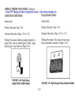
E-5.1 Waterproofing Surface Electrodes E-22
E-5.2 Preparation for Underwater Shielded Metal Arc Welding E-24
E-6 LOSS OF VOICE COMMUNICATIONS E-26
E-7 FRICTION STUD WELDER E-26
E-7.1 Principle of Operation E-26
E-7.2 Advantages E-26
E-7.3 Equipment Requirements E-27
E-7.3.1 Equipment Details E-27
Glossary Glossary-1
Index Index-1
S0300-BB-MAN-010
Change B ix
2-1 Underwater Oxygen-Arc Cutting Electrodes 2-3
2-2 Underwater Oxygen-Arc Electrode Designs 2-4
2-3 Drag Techniques for Cutting Steel with Steel-Tubular Electrodes 2-12
2-4 Technique for Cutting Steel Less Than 1/4 Inch with Steel-Tubular Electrodes 2-16
2-5 Technique for Piercing Holes in Steel Plate using the Oxy-Arc Process with
Steel Tubular Electrodes 2-17
2-6a Underwater Oxygen-Arc Cutting Torch Breakdown (Arcair) 2-19
2-6b Underwater Oxygen-Arc Cutting Torch Breakdown (BROCO) 2-20
2-6c Underwater Oxygen-Arc Cutting Torch Breakdown (Craftsweld) 2-21
2-7 Technique for Cutting Steel Using Exothermic Electrode 2-29
2-8 Seeler Kerie Cable Control Panel 2-36
2-9 Typical Kerie Cable Set Up 2-38
2-10 Technique for Underwater Shielded Metal-Arc Cutting of Thick Plate and
Round Stock 2-47
3-1 Test Specimen for Tee Fillet Weld 3-5
3-2 The Underwater Welding Arc 3-9
3-3 Parts of a Weld 3-11
3-4 Self-Consuming Technique for Underwater Shielded Metal Arc Welding
of Horizontal Fillet Welds 3-16
3-5 Self-Consuming Technique for Underwater Shielded Metal Arc Welding
of Vertical Fillet Welds 3-18
3-6 Technique for Underwater Shielded Metal Arc Welding of Overhead
Fillet Welds 3-19
LIST OF ILLUSTRATIONS
Figure Title Page
S0300-BB-MAN-010
x
3-7 Feeding-In Technique for Underwater Shielded Metal Arc Welding of
Fillet Welds in Wide-Gap Joints 3-21
3-8 Repair Method for Cracks in Underwater Structures Using a Rectangular Patch 3-23
3-9 Repair Methods for Cracks in Underwater Structures Using a Circular Patch 3-24
3-10 A Typical Underwater Welding Electrode Holder 3-26
4-1 Typical Arrangement of Underwater Arc Cutting Equipment 4-2
4-2 MK12 SSDS Welding Shield 4-3
4-3 MK1, MOD 0 Mask and Lens Holder Assembly 4-4
4-4 Superlite-17B/NS Helmet and Lens Holder Assembly 4-5
4-5 MK 12 Helmet Lens Holder Assembly with Parts Identification 4-6
4-6 Superlite-17B/NS Welding Lens Holder with Parts Identification 4-7
4-7 Typical Welding Generator and Power-Converter Control Panel 4-10
4-8 Equipment Arrangement for Welding and Cutting Straight Polarity 4-12
4-9 Tong Test Ammeter 4-14
4-10 Voltage Drop in Welding Cables 4-18
E-1 Arcwater Torch Assembly E-3
E-2 Thermic Lance Holder Assembly E-9
E-3 Standard Thermic Lance Equipment Set Up E-9
E-4 Standard Surface Cutting Torch with Underwater Spacer Sleeve E-15
E-5 Starting the Cut at the Edge of a Plate E-19
E-6 Starting a Cut in the Central Portion of a Plate E-20
E-7 Restarting the Cut E-21
E-8 Friction Stud Welder E-28
S0300-BB-MAN-010
xi (xii blank)
2-1 Cutting Amperage Requirements for Steel-Tubular Electrodes 2-6
2-2 Oxygen Regulator Settings for Oxygen-Arc Cutting Electrodes (Hose Lengths
50 Foot and 200 Foot) 2-7
2-3 Material Consumption using Steel-Tubular Electrodes 2-10
2-4 Recommended Power Settings for Cable
Length/Size for Ultrathermic Electrodes 2-24
2-5 Exothermic Electrode Consumption Guide 2-26
2-6 Oxygen Regulator Settings for Kerie Cable Cutting 2-41
2-7 Kerie Cable Size/Metal to be cut 2-42
2-8 Kerie Cable Oxygen and Cable Consumption Ratio 2-42
2-9 Material Requirements for Underwater Shielded Metal-Arc Cutting 2-45
3-1 Guide to Steels and Electrodes for Wet Welding 3-4
3-2 Electrodes for Underwater Shielded Metal Arc Welding 3-7
3-3 Recommended Amperage Settings for Wet Welding to Depths of 50 Feet 3-7
4-1 Recommended Equipment for Underwater Arc Cutting and Welding 4-8
4-2 Equipment Load-out for Wet Cutting/Welding Operations 4-22
4-3 List of Manufacturers 4-26
4-4 Parts Information 4-28
A-1 Salvage Documentation Matrix A-2
E-1 Arcwater Operating Data Cutting Carbon Steel E-6
E-2 Equipment and Material Requirements for Underwater
MAPP Gas Cutting E-11
E-3 Regulator Gauge Settings E-13
E-4 Recommended Cutting Tip Sizes E-14
E-5 Recommended Pressure Settings and Hose Size Selection Chart E-17
E-6 Surface Welding Electrodes Suitable for Wet Welding E-23
E-7 Recommended Amperage Settings for Wet Welding to Depths of 50 FSW E-25
LIST OF TABLES
Table Title Page
S0300-BB-MAN-010
xii
S0300-BB-MAN-010
xiii (xiv blank)
STANDARD NAVY SYNTAX SUMMARY
This manual utilizes standard Navy syntax as pertains to permissive, advisory, and mandatory lan-
guage. The concept of word usage and intended meaning which as been adhered to in preparing
this manual is as follows:
“Shall” has been used only when application of a procedure is mandatory.
“Should” has been used only when application of a procedure is recommended.
“May” and “need not” have been used only when application of a procedure is
discretionary.
“Will” has been used only to indicate futurity; never to indicate any degree of requirement
for application of a procedure.
Throughout the manual “electrode” and “rod” have been used interchangeably.
S0300-BB-MAN-010
Change A xv
SAFETY SUMMARY
This Safety Summary contains all specific WARNINGS and CAUTIONS appearing
elsewhere in this manual. Should situations arise that are not covered by the general and spe-
cific safety precautions, the Commanding Officer or other authority will issue orders, as deemed
necessary, to cover the situation.
GUIDELINES
Extensive guidelines for safety can be found in the OPNAV 5100 Series instruction manual,
"Navy Safety Precautions." Personnel required to perform underwater cutting or welding
operations shall be graduates of a U. S. Navy Diving School, thoroughly trained and
equipped not only to perform routine underwater and "top-side" procedures but also to react
appropriately to unusual or non-routine situations.
Diving Officers, Diving Supervisors and members of dive teams likely to be involved in sal-
vage requiring underwater cutting or welding should continuously conduct safety indoctri-
nation lectures and exercises aimed at reducing hazards and at reacting appropriately to unusual
situations.
PRECAUTIONS
The WARNINGS and CAUTIONS contained in this manual and listed below are ref-
erenced by page number. In addition, the general precautions listed below are offered as part of
this Safety Summary. All personnel responsible for or engaged in underwater cutting or weld-
ing should:
• Read and comprehend this manual.
• Observe all warnings, cautions and notes listed herein.
• Know the capabilities of assigned equipment and strictly follow operational proce-
dures.
Definitions of warnings and cautions are as follows:
WARNING
A statement used to call particular attention to an action or
procedural step which, if not strictly followed, could result
in the injury or death of personnel.
S0300-BB-MAN-010
xvi Change A
The following warning and caution statements appear in this manual and are repeated here for
emphasis:
CAUTION
A statement used to provoke notice, awareness, and attention
from personnel regarding an action or procedural step which,
if not followed, could result in possible injury or equipment
malfunction.
WARNING
Serious injury or death may result when adequate pre-
cautions are not followed during underwater cutting
or welding operations. Supervisors shall ensure that all
personnel become thoroughly familiar with the safety
precautions covered in Appendix D. (pages 2-1, 3-1)
WARNING
Under no circumstances shall compressed air be substi-
tuted for oxygen in underwater cutting operations due to
the danger of contaminating oxygen regulators and
hoses with oil residue (hydrocarbons). (page 2-1)
WARNING
The position of the ground in relation to the diver must be
such that at no time does the diver or equipment
become positioned between the ground and the electrode.
The diver must avoid becoming part of the electrical cir-
cuit. (pages 2-1, 2-26, 3-1, D-7, E-4)
S0300-BB-MAN-010
Change A xvii
WARNING
AC power shall not be used for underwater cutting and
welding due to the extreme danger involved with AC
current underwater. Electrical shock produced by AC
current prevents voluntary relaxation of the muscles
controlling the hand. Consequently, the diver may be
unable to let go if his body or equipment accidentally
enters the electrical circuit. (pages 2-2, 3-1, 4-9, D-3)
WARNING
When the electrode has been consumed to within 3
inches of the torch, stop the cut and signal for
SWITCH OFF before attempting to change electrodes.
Maintain the torch in the cutting position until the ten-
der (phone talker) acknowledges SWITCH OFF. Then
tap the electrode twice to make sure the current is off.
This safety precaution is mandatory, regardless of the
type of electrode being used. (page 2-14)
WARNING
Hydrocarbons ignite almost spontaneously in the pres-
ence of oxygen. Never allow oxygen-carrying compo-
nents to come in contact with oil or grease. (pages 2-18,
D-10)
WARNING
It is unsafe to operate the torch without the flash arrestor
in place. To do so may cause injury and/or destroy the
torch. (pages 2-22, 4-17)
S0300-BB-MAN-010
xviii Change A
WARNING
Never get between the electrode holder and the striker
plate (ground) when the switch is on. (page 2-31)
WARNING
Do NOT attempt to speed up the cutting by creating a
fire or inferno deep inside the metal. Such a situation can
lead to an explosion. (pages 2-33, D-1)
WARNING
The Kerie Cable WILL NOT cut rock or concrete
either above or below water. To attempt to do so may
create an explosion causing serious injury or death.
(page 2-33)
WARNING
The equipment should not be used to cut non-ferrous
metals underwater since they do not oxidize and have to
be melted. Experience has shown that this can result in a
violent explosion which could be fatal. (page 2-34)
WARNING
It is very important that ignition NOT occur with
oxygen pressure too low. To do so will cause the cable to
burn inside itself, and as full pressure is applied, the flame
will burn out sideways along the length of the cable in a
series of blow holes that can cause diver injury.
(page 2-37)
S0300-BB-MAN-010
Change A xix
WARNING
Oxygen partial pressure increases with water depth,
thereby creating a fire hazard in habitat environments.
No habitat welding will be performed in an air environ-
ment at depths greater than 60 FSW. Habitats shall be
filled with an inert gas at depths greater than 60 FSW.
(page 3-2)
WARNING
A diver is at risk to severe electrical shock when performing
a cutting or welding operation while only partially
immersed in water. Hence, the splash zone is the most
hazardous location in which a diver can be placed.
(page D-2)
WARNING
NEVER bring a cutting torch into a bell with the oxygen
on or with the welding generator running. (page D-2)
WARNING
When the arcwater electrode has been consumed to
within 1.5 inches of the torch, stop the cut and signal for
SWITCH and water OFF before changing the electrode.
Maintain the torch in the cutting position until the tender
signals SWITCH OFF. Then tap the electrode twice to
make sure the current is off. This safety precaution is
mandatory, regardless of the type of electrode used. (page
E-5)
S0300-BB-MAN-010
xx Change A
WARNING
This process produces large quantities of hydrogen gas.
When combined with oxygen, these concentrations are
highly explosive and will produce random explosions of
some magnitude. Several divers engaged in salvage work
have been killed using this process. (page E-5)
WARNING
Thermic Lances or Burn Bars are NOT to be used by
divers while underwater or by topside personnel per-
forming a cut below the waterline while a diver is in the
water. However, during situations where it would be
impossible to place a diver in position for cutting and
where the cutting can be accomplished from the sur-
face, the Thermic Lance may be used with EXTREME
CAUTION! (page E-6)
WARNING
Always wear protective clothing when using the Thermic
lance: full protective suit, leather gloves, tinted face shield,
and a hard hat. (page E-7)
WARNING
Acetylene is very unstable at pressures above 15 psi, and
is NOT used for underwater cutting. (page E-10)
S0300-BB-MAN-010
Change A xxi
CAUTION
The hand should never be closer than 4 inches from the
electrode tip. Therefore, as the electrode is consumed and
becomes manageable, the pool que grip can be released. (page
2-14)
CAUTION
Pushing the electrode into the hole too fast will result in a
shower of spatter, which may damage the diving equip-
ment and/or result in a blow-back. (page 2-15)
CAUTION
It is important that the proper washer-collet combination is
used. An oversize washer will allow the electrode to bottom
on the flashback arrestor, creating electrolysis and possible
arcing. An undersize washer will restrict the flow of oxygen
to the larger bore electrodes, causing inefficient cutting.
(page 2-22)
CAUTION
Unlike steel-tubular rods that stop burning the instant the
electrical circuit is broken, the exothermic electrodes will
continue to burn as long as oxygen is flowing through the
electrode. (page 2-25)
S0300-BB-MAN-010
xxii Change A
CAUTION
When the electrode burns down to within 3 inches of the torch,
call for SWITCH OFF. Release the trigger to extinguish the
electrode, since it will continue to burn when the electrical
power is off with oxygen still flowing. Do NOT attempt to
use the last 3 inches of the electrode. To do so will subject the
torch to unnecessary heat and possible damage. (page 2-27)
CAUTION
Burning the electrode shorter than the 3-inch minimum can
damage the torch interior. (page 2-30)
CAUTION
Ensure that the red insulating sleeve is correctly reinstalled
after replacing the Kerie Cable. (page 2-36)
CAUTION
Do not force or poke the cable into the material being cut,
since this will cause blow-back. (page 2-40)
CAUTION
Due to the flammability and toxicity of fumes from
waterproofing compounds, waterproofing must be conducted
in a well-ventilated space, clear of any open flames or spark-
producing machinery. (page 2-44, E-21)