Fluid Mechanics, Thermodynamics of TurbomachineryS.L. Dixon, B.Eng potx
Bạn đang xem bản rút gọn của tài liệu. Xem và tải ngay bản đầy đủ của tài liệu tại đây (3.21 MB, 353 trang )
Fluid Mechanics,
Thermodynamics of
Turbomachinery
S.L. Dixon, B.Eng., PH.D.
Senior Fellow at the University of Liverpool
FOURTH EDITION in SI/METRIC UNITS
Fluid Mechanics,
Thermodynamics of
Turbomachinery
FOURTH EDITION in SI/METRIC UNITS
In memory of
Avril and baby Paul
Fluid Mechanics,
Thermodynamics of
Turbomachinery
S. L. Dixon, B.Eng., Ph.D.
Senior Fellow at the University of Liverpool
FOURTH EDITION in SI/METRIC UNITS
Butterworth-Heinemann
Linacre House, Jordan Hill, Oxford OX2 8DP
225 Wildwood Avenue, Woburn, MA 01801-2041
A division of Reed Educational and Professional Publishing Ltd
A member of the Reed Elsevier plc group
First published by Pergamon Press Ltd 1966
Second edition 1975
Third edition 1978
Reprinted 1979, 1982 (twice), 1984, 1986, 1989, 1992, 1995
Fourth edition 1998
S.L. Dixon 1978, 1998
All rights reserved. No part of this publication
may be reproduced in any material form (including
photocopying or storing in any medium by electronic
means and whether or not transiently or incidentally
to some other use of this publication) without the
written permission of the copyright holder except
in accordance with the provisions of the Copyright,
Designs and Patents Act 1988 or under the terms of a
license issued by the Copyright Licensing Agency Ltd,
90 Tottenham Court Road, London, England W1P 9HE.
Applications for the copyright holder’s written permission
to reproduce any part of this publication should be addressed
to the publishers
British Library Cataloguing in Publication Data
A catalogue record for this book is available from the British Library
ISBN 0 7506 7059 2
Library of Congress Cataloguing in Publication Data
A catalogue record for this book is available from the Library of Congress
Typeset by Laser Words, Madras, India
Printed and bound in
Contents
PREFACE TO FOURTH EDITION ix
P
REFACE TO THIRD EDITION xi
A
CKNOWLEDGEMENTS xiii
L
IST OF SYMBOLS xv
1. Introduction: Dimensional Analysis: Similitude
1
Definition of a turbomachine 1
Units and dimensions 3
Dimensional analysis and performance laws 4
Incompressible fluid analysis 6
Performance characteristics 7
Variable geometry turbomachines 9
Specific speed 10
Cavitation 12
Compressible gas flow relations 15
Compressible fluid analysis 16
The inherent unsteadiness of the flow within turbomachines 20
References 21
Problems 22
2. Basic Thermodynamics, Fluid Mechanics: Definitions of Efficiency 23
Introduction 23
The equation of continuity 23
The first law of thermodynamics
internal energy 24
The momentum equation
Newton’s second law of motion 25
The second law of thermodynamics
entropy 29
Definitions of efficiency 30
Small stage or polytropic efficiency 35
Nozzle efficiency 41
Diffusers 43
References 53
Problems 53
vi
Contents
3. Two-dimensional Cascades 55
Introduction 55
Cascade nomenclature 56
Analysis of cascade forces 57
Energy losses 59
Lift and drag 59
Circulation and lift 61
Efficiency of a compressor cascade 62
Performance of two-dimensional cascades 63
The cascade wind tunnel 63
Cascade test results 65
Compressor cascade performance 68
Turbine cascade performance 70
Compressor cascade correlations 71
Fan blade design (McKenzie) 80
Turbine cascade correlation (Ainley) 81
Comparison of the profile loss in a cascade and in a turbine stage 86
Optimum space-chord ratio of turbine blades (Zweifel) 87
References 88
Problems 90
4. Axial-flow Turbines: Two-dimensional Theory 93
Introduction 93
Velocity diagrams of the axial turbine stage 93
Thermodynamics of the axial turbine stage 94
Stage losses and efficiency 96
Soderberg’s correlation 97
Types of axial turbine design 99
Stage reaction 101
Diffusion within blade rows 103
Choice of reaction and effect on efficiency 107
Design point efficiency of a turbine stage 108
Maximum total-to-static efficiency of a reversible turbine stage 112
Stresses in turbine rotor blades 114
Turbine flow characteristics 120
Flow characteristics of a multistage turbine 122
The Wells turbine 124
References 132
Problems 133
5. Axial-flow Compressors and Fans 137
Introduction 137
Two-dimensional analysis of the compressor stage 138
Velocity diagrams of the compressor stage 140
Thermodynamics of the compressor stage 141
Contents
vii
Stage loss relationships and efficiency 142
Reaction ratio 143
Choice of reaction 143
Stage loading 144
Simplified off-design performance 145
Stage pressure rise 147
Pressure ratio of a multistage compressor 148
Estimation of compressor stage efficiency 149
Stall and surge phenomena in compressors 154
Control of flow instabilities 159
Axial-flow ducted fans 160
Blade element theory 162
Blade element efficiency 163
Lift coefficient of a fan aerofoil 164
References 165
Problems 166
6. Three-dimensional Flows in Axial Turbomachines 169
Introduction 169
Theory of radial equilibrium 169
The indirect problem 171
The direct problem 179
Compressible flow through a fixed blade row 180
Constant specific mass flow 181
Off-design performance of a stage 183
Free-vortex turbine stage 184
Actuator disc approach 186
Blade row interaction effects 190
Computer-aided methods of solving the through-flow problem 191
Secondary flows 193
References 195
Problems 196
7. Centrifugal Pumps, Fans and Compressors 199
Introduction 199
Some definitions 200
Theoretical analysis of a centrifugal compressor 202
Inlet casing 203
Impeller 203
Conservation of rothalpy 204
Diffuser 205
Inlet velocity limitations 205
Optimum design of a pump inlet 206
Optimum design of a centrifugal compressor inlet 208
Slip factor 213
Head increase of a centrifugal pump 218
viii
Contents
Performance of centrifugal compressors 219
The diffuser system 227
Choking in a compressor stage 230
References 232
Problems 233
8. Radial Flow Gas Turbines 236
Introduction 236
Types of inward flow radial turbine 237
Thermodynamics of the 90 deg IFR turbine 239
Basic design of the rotor 241
Nominal design point efficiency 242
Mach number relations 246
Loss coefficients in 90 deg IFR turbines 247
Optimum efficiency considerations 248
Criterion for minimum number of blades 253
Design considerations for rotor exit 256
Incidence losses 260
Significance and application of specific speed 263
Optimum design selection of 90 deg IFR turbines 266
Clearance and windage losses 269
Pressure ratio limits of the 90 deg IFR turbine 269
Cooled 90 deg IFR turbines 271
References 272
Problems 273
9. Hydraulic Turbines 277
Introduction 277
Hydraulic turbines 278
The Pelton turbine 281
Reaction turbines 290
The Francis turbine 290
The Kaplan turbine 296
Effect of size on turbomachine efficiency 299
Cavitation 301
References 305
Problems 306
Bibliography 309
Appendix 1. Conversion of British and US Units to SI Units 310
Appendix 2. Answers to Problems 311
Index 315
Preface to the Fourth Edition
It is now twenty years since the third edition of this book was published and in
that period many advances have been made to the art and science of turboma-
chinery design. Knowledge of the flow processes within turbomachines has increased
dramatically resulting in the appearance of new and innovative designs. Some of
the long-standing, apparently intractable, problems such as surge and rotating stall
have begun to yield to new methods of control. New types of flow machine have
made their appearance (e.g. the Wells turbine and the axi-fuge compressor) and
some changes have been made to established design procedures. Much attention
is now being given to blade and flow passage design using computational fluid
dynamics (CFD) and this must eventually bring forth further design and flow effi-
ciency improvements. However, the fundamentals do not change and this book is
still concerned with the basics of the subject as well as looking at new ideas.
The book was originally perceived as a text for students taking an Honours degree
in engineering which included turbomachines as well as assisting those undertaking
more advanced postgraduate courses in the subject. The book was written for engi-
neers rather than mathematicians. Much stress is laid on physical concepts rather
than mathematics and the use of specialised mathematical techniques is mostly kept
to a minimum. The book should continue to be of use to engineers in industry
and technological establishments, especially as brief reviews are included on many
important aspects of turbomachinery giving pointers to more advanced sources of
information. For those looking towards the wider reaches of the subject area some
interesting reading is contained in the bibliography. It might be of interest to know
that the third edition was published in four languages.
A fairly large number of additions and extensions have been included in the
book from the new material mentioned as well as “tidying up” various sections
no longer to my liking. Additions include some details of a new method of fan
blade design, the determination of the design point efficiency of a turbine stage,
sections on centrifugal stresses in turbine blades and blade cooling, control of flow
instabilities in axial-flow compressors, design of the Wells turbine, consideration of
rothalpy conservation in impellers (and rotors), defining and calculating the optimum
efficiency of inward flow turbines and comparison with the nominal design. A
number of extensions of existing topics have been included such as updating and
extending the treatment and application of diffuser research, effect of prerotation
of the flow in centrifugal compressors and the use of backward swept vanes on
their performance, also changes in the design philosophy concerning the blading of
axial-flow compressors. The original chapter on radial flow turbines has been split
into two chapters; one dealing with radial gas turbines with some new extensions
and the other on hydraulic turbines. In a world striving for a ‘greener’ future it was
felt that there would now be more than just a little interest in hydraulic turbines. It
is a subject that is usually included in many mechanical engineering courses. This
chapter includes a few new ideas which could be of some interest.
x
Preface to the Fourth Edition
A large number of illustrative examples have been included in the text and many
new problems have been added at the end of most chapters (answers are given at the
end of the book)! It is planned to publish a new supplementary text called Solutions
Manual, hopefully, shortly after this present text book is due to appear, giving the
complete and detailed solutions of the unsolved problems.
S. Lawrence Dixon
Preface to Third Edition
Several modifications have been incorporated into the text in the light of recent
advances in some aspects of the subject. Further information on the interesting
phenomenon of cavitation has been included and a new section on the optimum
design of a pump inlet together with a worked example have been added which
take into account recently published data on cavitation limitations. The chapter on
three-dimensional flows in axial turbomachines has been extended; in particular the
section concerning the constant specific mass flow design of a turbine nozzle has
been clarified and now includes the flow equations for a following rotor row. Some
minor alterations on the definition of blade shapes were needed so I have taken the
opportunity of including a simplified version of the parabolic arc camber line as
used for some low camber blading.
Despite careful proof reading a number of errors still managed to elude me in the
second edition. I am most grateful to those readers who have detected errors and
communicated with me about them.
In order to assist the reader I have (at last) added a list of symbols used in the
text.
S.L.D.
xi
This is a
blank page
This is a
blank page
This is a
blank page
Acknowledgements
The author is indebted to a number of people and manufacturing organisations for
their help and support; in particular the following are thanked:
Professor W. A. Woods, formerly of Queen Mary College, University of London
and a former colleague at the University of Liverpool for his encouragement of the
idea of a fourth edition of this book as well as providing papers and suggestions for
some new items to be included. Professor F. A. Lyman of Syracuse University, New
York and Professor J. Moore of Virginia Polytechnic Institute and State University,
Virginia, for their helpful correspondence and ideas concerning the vexed question
of the conservation of rothalpy in turbomachines. Dr Y. R. Mayhew is thanked for
supplying me with generous amounts of material on units and dimensions and the
latest state of play on SI Units.
Thanks are also given to the following organisations for providing me with illus-
trative material for use in the book, product information and, in one case, useful
background historical information:
Sulzer Hydro of Zurich, Switzerland; Rolls-Royce of Derby, England; Voith
Hydro Inc., Pennsylvania; and Kvaerner Energy, Norway.
Last, but by no means least, to my wife Rose, whose quiet patience and support
enabled this new edition to be prepared.
This is a
blank page
This is a
blank page
This is a
blank page
List of Symbols
A area
a sonic velocity, position of maximum camber
b passage width, maximum camber
C
f
tangential force coefficient
C
L
,C
D
lift and drag coefficients
C
p
specific heat at constant pressure, pressure coefficient, pressure rise
coefficient
C
pi
ideal pressure rise coefficient
C
v
specific heat at constant volume
C
X
,C
Y
axial and tangential force coefficients
c absolute velocity
c
o
spouting velocity
D drag force, diameter
D
eq
equivalent diffusion ratio
D
h
hydraulic mean diameter
E, e energy, specific energy
F
c
centrifugal force in blade
f acceleration, friction factor
g gravitational acceleration
H head, blade height
H
E
effective head
H
f
head loss fue to friction
H
G
gross head
H
S
net positive suction head (NPSH)
h specific enthalpy
I rothalpy
i incidence angle
K, k constants
K
N
nozzle velocity coefficient
L lift force, length of diffuser wall
l blade chord length, pipe length
M Mach number
m mass, molecular ‘weight’
N rotational speed, axial length of diffuser
N
S
specific speed (rev)
N
SP
power specific speed (rev)
N
SS
suction specific speed (rev)
n number of stages, polytropic index
p pressure
xvi
Fluid Mechanics, Thermodynamics of Turbomachinery
p
a
atmospheric pressure
p
v
vapour pressure
Q heat transfer, volume flow rate
q dryness fraction
R reaction, specific gas constant
Re Reynolds number
R
H
reheat factor
R
o
universal gas constant
r radius
S entropy, power ratio
s blade pitch, specific entropy
T temperature
t time, thickness
U blade speed, internal energy
u specific internal energy
V, v volume, specific volume
W work transfer
W specific work transfer
w relative velocity
X axial force
x, y, z Cartesian coordinate directions
Y tangential force, actual tangential blade load per unit span
Y
id
ideal tangential blade load per unit span
Y
k
tip clearance loss coefficient
Y
p
profile loss coefficient
Y
S
net secondary loss coefficient
Z number of blades, Ainley blade loading parameter
˛ absolute flow angle
ˇ relative flow angle
circulation
ratio of specific heats
υ deviation angle
ε fluid deflection angle, cooling effectiveness
enthalpy loss coefficient, total pressure loss coefficient
Á efficiency
minimum opening at cascade exit
 blade camber angle, wake momentum thickness
profile loss coefficient
dynamic viscosity
kinematic viscosity, blade stagger angle, velocity ratio
density
slip factor, solidity
b
blade cavitation coefficient
c
Thoma’s coefficient, centrifugal stress
torque
List of Symbols
xvii
flow coefficient, velocity ratio
stage loading factor
speed of rotation (rad/s)
S
specific speed (rad)
SP
power specific speed (rad)
SS
suction specific speed (rad)
ω vorticity
ω stagnation pressure loss coefficient
Subscripts
av average
c compressor, critical
D diffuser
e exit
h hydraulic, hub
i inlet, impeller
id ideal
is isentropic
m mean, meridional, mechanical, material
N nozzle
n normal component
o stagnation property, overall
p polytropic, constant pressure
R reversible process, rotor
r radial
rel relative
s isentropic, stall condition
ss stage isentropic
t turbine, tip, transverse
v velocity
x, y, z cartesian coordinate components
 tangential
Superscript
Ð time rate of change
- average
0
blade angle (as distinct from flow angle)
* nominal condition
This is a
blank page
This is a
blank page
This is a
blank page
CHAPTER 1
Introduction: Dimensional
Analysis: Similitude
If you have known one you have known all.
(TERENCE
, Phormio.
)
Definition of a turbomachine
We classify as turbomachines all those devices in which energy is transferred
either to, or from, a continuously flowing fluid by the dynamic action of one or
more moving blade rows. The word turbo or turbinis is of Latin origin and implies
that which spins or whirls around. Essentially, a rotating blade row, a rotor or an
impeller changes the stagnation enthalpy of the fluid moving through it by either
doing positive or negative work, depending upon the effect required of the machine.
These enthalpy changes are intimately linked with the pressure changes occurring
simulataneously in the fluid.
The definition of a turbomachine as stated above, is rather too general for the
purposes of this book as it embraces open turbomachines such as propellers, wind
turbines and unshrouded fans, all of which influence the state of a not readily
quantifiable flow of a fluid. The subject fluid mechanics, thermodynamics of turbo-
machinery, therefore, is limited to machines enclosed by a closely fitting casing or
shroud through which a readily measurable quantity of fluid passes in unit time.
The subject of open turbomachines is covered by the classic text of Glauert (1959)
or by Duncan et al. (1970), the elementary treatment of propellers by general fluid
mechanics textbooks such as Streeter and Wylie (1979) or Massey (1979), and the
important, still developing subject of wind turbines, by Freris (1990).
Two main categories of turbomachine are identified: firstly, those which absorb
power to increase the fluid pressure or head (ducted fans, compressors and pumps);
secondly, those that produce power by expanding fluid to a lower pressure or head
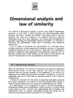
(hydraulic, steam and gas turbines). Figure 1.1 shows, in a simple diagrammatic
form, a selection of the many different varieties of turbomachine encountered in
practice. The reason that so many different types of either pump (compressor) or
turbine are in use is because of the almost infinite range of service requirements.
Generally speaking, for a given set of operating requirements there is one type of
pump or turbine best suited to provide optimum conditions of operation. This point
is discussed more fully in the section of this chapter concerned with specific speed.
Turbomachines are further categorised according to the nature of the flow path
throughthepassagesoftherotor.Whenthepathofthethrough-flow iswhollyormainly
parallel to the axis of rotation, the device is termed an axial flow turbomachine (e.g.
1
2
Fluid Mechanics, Thermodynamics of Turbomachinery
FIG. 1.1. Diagrammatic form of various types of turbomachine.
Figure 1.1(a)and (e)).When the pathof thethrough-flow iswholly ormainlyin aplane
perpendicular tothe rotationaxis, thedevice is termed a radial flow turbomachine (e.g.
Figure 1.1(c)).More detailed sketchesof radialflow machinesare givenin Figures 7.1,
7.2, 8.2 and 8.3. Mixed flow turbomachines are widely used. The term mixed flow in
this context refers to the direction of the through-flow at rotor outlet when both radial
and axial velocity components are present in significant amounts. Figure 1.1(b) shows
a mixed flow pump and Figure 1.1(d) a mixed flow hydraulic turbine.
One further category should be mentioned. All turbomachines can be classified
as either impulse or reaction machines according to whether pressure changes are
Introduction: Dimensional Analysis: Similitude
3
absent or present respectively in the flow through the rotor. In an impulse machine
all the pressure change takes place in one or more nozzles, the fluid being directed
onto the rotor. The Pelton wheel, Figure 1.1(f), is an example of an impulse turbine.
The main purpose of this book is to examine, through the laws of fluid mechanics
and thermodynamics, the means by which the energy transfer is achieved in the
chief types of turbomachine, together with the differing behaviour of individual
types in operation. Methods of analysing the flow processes differ depending upon
the geometrical configuration of the machine, on whether the fluid can be regarded
as incompressible or not, and whether the machine absorbs or produces work. As
far as possible, a unified treatment is adopted so that machines having similar
configurations and function are considered together.
Units and dimensions
The International System of Units, SI (le Syst
`
eme International d’Unit
´
es)
is a unified self-consistent system of measurement units based on the MKS
(metre
kilogram second) system. It is a simple, logical system based upon decimal
relationships between units making it easy to use. The most recent detailed
description of SI has been published in 1986 by HMSO. For an explanation of
the relationship between, and use of, physical quantities, units and numerical values
see Quantities, Units and Symbols, published by The Royal Society (1975) or refer
to ISO 31/0-1981.
Great Britain was the first of the English-speaking countries to begin, in the
1960s, the long process of abandoning the old Imperial System of Units in favour
of the International System of Units, and was soon followed by Canada, Australia,
New Zealand and South Africa. In the USA a ten year voluntary plan of conversion
to SI units was commenced in 1971. In 1975 US President Ford signed the Metric
Conversion Act which coordinated the metrication of units, but did so without
specifying a schedule of conversion. Industries heavily involved in international
trade (cars, aircraft, food and drink) have, however, been quick to change to SI for
obvious economic reasons, but others have been reluctant to change.
SI has now become established as the only system of units used for teaching
engineering in colleges, schools and universities in most industrialised countries
throughout the world. The Imperial System was derived arbitrarily and has no
consistent numerical base, making it confusing and difficult to learn. In this book
all numerical problems involving units are performed in metric units as this is more
convenient than attempting to use a mixture of the two systems. However, it is
recognised that some problems exist as a result of the conversion to SI units. One
of these is that many valuable papers and texts written prior to 1969 contain data
in the old system of units and would need converting to SI units. A brief summary
of the conversion factors between the more frequently used Imperial units and SI
units is given in Appendix 1 of this book.
Some SI units
The SI basic units used in fluid mechanics and thermodynamics are the metre
(m), kilogram (kg), second (s) and thermodynamic temperature (K). All the other
units used in this book are derived from these basic units. The unit of force is the
4
Fluid Mechanics, Thermodynamics of Turbomachinery
newton (N), defined as that force which, when applied to a mass of 1 kilogram,
gives an acceleration to the mass of 1m/s
2
. The recommended unit of pressure is
the pascal (Pa) which is the pressure produced by a force of 1 newton uniformly
distributed over an area of 1square metre. Several other units of pressure are in wide-
spread use, however, foremost of these being the bar. Much basic data concerning
properties of substances (steam and gas tables, charts, etc.) have been prepared in SI
units with pressure given in bars and it is acknowledged that this alternative unit of
pressure will continue to be used for some time as a matter of expediency. It is noted
that 1bar equals 10
5
Pa (i.e. 10
5
N/m
2
), roughly the pressure of the atmosphere at
sea level, and is perhaps an inconveniently large unit for pressure in the field of
turbomachinery anyway! In this book the convenient size of the kilopascal (kPa) is
found to be the most useful multiple of the recommended unit and is extensively
used in most calculations and examples.
In SI the units of all forms of energy are the same as for work. The unit of energy
is the joule (J) which is the work done when a force of 1 newton is displaced through
a distance of 1 metre in the direction of the force, e.g. kinetic energy (
1
2
mc
2
) has the
dimensions kg ð m
2
/s
2
; however, 1 kg D 1Ns
2
/m from the definition of the newton
given above. Hence, the units of kinetic energy must be Nm D J upon substituting
dimensions.
The watt (W) is the unit of power; when 1 watt is applied for 1second to a system
the input of energy to that system is 1 joule (i.e. 1 J).
The hertz (Hz) is the number of repetitions of a regular occurrence in 1second.
Instead of writing c/s for cycles/sec, Hz is used instead.
The unit of thermodynamic temperature is the kelvin (K), written without the
°
sign, and is the fraction 1/273.16 of the thermodynamic temperature of the triple
point of water. The degree celsius (
°
C) is equal to the unit kelvin. Zero on the
celsius scale is the temperature of the ice point (273.15 K). Specific heat capacity,
or simply specific heat, is expressed as J/kg K or as J/kg
°
C.
Dynamic viscosity, dimensions ML
1
T
1
, has the SI units of pascal seconds, i.e.
M
LT
Á
kg
m.s
D
N.s
2
m.
2
s
D Pa s.
Hydraulic engineers find it convenient to express pressure in terms of head of a
liquid. The static pressure at any point in a liquid at rest is, relative to the pressure
acting on the free surface, proportional to the vertical distance of the free surface
above that point. The head H is simply the height of a column of the liquid which
can be supported by this pressure. If is the mass density (kg/m
3
) and g the local
gravitational acceleration (m/s
2
), then the static pressure p (relative to atmospheric
pressure) is p D gH, where H is in metres and p is in pascals (or N/m
2
). This is
left for the student to verify as a simple exercise.
Dimensional analysis and performance laws
The widest comprehension of the general behaviour of all turbomachines is,
without doubt, obtained from dimensional analysis. This is the formal procedure
whereby the group of variables representing some physical situation is reduced
Introduction: Dimensional Analysis: Similitude
5
into a smaller number of dimensionless groups. When the number of indepen-
dent variables is not too great, dimensional analysis enables experimental relations
between variables to be found with the greatest economy of effort. Dimensional
analysis applied to turbomachines has two further important uses: (a) prediction
of a prototype’s performance from tests conducted on a scale model (similitude);
(b) determination of the most suitable type of machine, on the basis of maximum
efficiency, for a specified range of head, speed and flow rate. Several methods of
constructing non-dimensional groups have been described by Douglas et al. (1995)
and by Shames (1992) among other authors. The subject of dimensional analysis was
made simple and much more interesting by Edward Taylor (1974) in his comprehen-
sive account of the subject. It is assumed here that the basic techniques of forming
non-dimensional groups have already been acquired by the student.
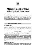
Adopting the simple approach of elementary thermodynamics, an imaginary enve-
lope (called a control surface) of fixed shape, position and orientation is drawn
around the turbomachine (Figure 1.2). Across this boundary, fluid flows steadily,
entering at station 1 and leaving at station 2. As well as the flow of fluid there
is a flow of work across the control surface, transmitted by the shaft either to, or
from, the machine. For the present all details of the flow within the machine can
be ignored and only externally observed features such as shaft speed, flow rate,
torque and change in fluid properties across the machine need be considered. To be
specific, let the turbomachine be a pump (although the analysis could apply to other
classes of turbomachine) driven by an electric motor. The speed of rotation N, can
be adjusted by altering the current to the motor; the volume flow rate Q, can be
independently adjusted by means of a throttle valve. For fixed values of the set Q
and N, all other variables such as torque , head H, are thereby established. The
choice of Q and N as control variables is clearly arbitrary and any other pair of
independent variables such as and H could equally well have been chosen. The
important point to recognise is, that there are for this pump, two control variables.
If the fluid flowing is changed for another of different density , and viscosity
, the performance of the machine will be affected. Note, also, that for a turbo-
machine handling compressible fluids, other fluid properties are important and are
discussed later.
So far we have considered only one particular turbomachine, namely a pump of
a given size. To extend the range of this discussion, the effect of the geometric
FIG. 1.2. Turbomachine considered as a control volume.
6
Fluid Mechanics, Thermodynamics of Turbomachinery
variables on the performance must now be included. The size of machine is char-
acterised by the impeller diameter D, and the shape can be expressed by a number
of length ratios, l
1
/D, l
2
/D, etc.
Incompressible fluid analysis
The performance of a turbomachine can now be expressed in terms of the control
variables, geometric variables and fluid properties. For the hydraulic pump it is
convenient to regard the net energy transfer gH, the efficiency Á, and power supplied
P, as dependent variables and to write the three functional relationships as
gH D f
1
Q, N, D, , ,
l
1
D
,
l
2
D
,
,1.1a
Á D f
2
Q, N, D, , ,
l
1
D
,
l
2
D
,
,1.1b
P D f
3
Q, N, D, , ,
l
1
D
,
l
2
D
,
,1.1c
By the procedure of dimensional analysis using the three primary dimensions, mass,
length and time, or alternatively, using three of the independent variables we can
form the dimensionless groups. The latter, more direct procedure, requires that the
variables selected, , N, D, do not of themselves form a dimensionless group. The
selection of , N, D as common factors avoids the appearance of special fluid terms
(e.g. , Q) in more than one group and allows gH, Á and P to be made explicit.
Hence the three relationships reduce to the following easily verified forms.
Energy transfer coefficient, sometimes called head coefficient
D
gH
ND
2
D f
4
Q
ND
3
,
ND
2
,
l
1
D
,
l
2
D
,
,1.2a
Á D f
5
Q
ND
3
,
ND
2
,
l
1
D
,
l
2
D
,
.1.2b
Power coefficient
O
P D
P
N
3
D
5
D f
6
Q
ND
3
,
ND
2
,
l
1
D
,
l
2
D
,
. (1.2c)
The non-dimensional group Q/ND
3
is a volumetric flow coefficient and
ND
2
/ is a form of Reynolds number, Re. In axial flow turbomachines, an
alternative to Q/ND
3
which is frequently used is the velocity (or flow) coefficient
D c
x
/U where U is blade tip speed and c
x
the average axial velocity. Since
Q D c
x
ð flow area / c
x
D
2
and U / ND.
then
Q
ND
3
/
c
x
U
.