Theory and Design of Air Cushion Craft II ppt
Bạn đang xem bản rút gọn của tài liệu. Xem và tải ngay bản đầy đủ của tài liệu tại đây (45.78 MB, 647 trang )
Theory
and
Design
of Air
Cushion Craft
This page intentionally left blank
Theory
and
Design
of Air
Cushion Craft
Liang
Yun
Deputy
Chief Naval Architect
of the
Marine
Design
&
Research
Institute
of
China
Alan Bliault
Shell
International Exploration
and
Production
Ho/Ian
A
member
of the
Hodder
Headline
Group
LONDON
Copublished
in
North, Central
and
South America
by
John Wiley
&
Sons Inc.,
New
York
•
Toronto
First published
in
Great
Britain
in
2000
by
Arnold,
a
member
of the
Hodder Headline Group,
338
Huston
Road, London
NW1 3BH
Copublished
in
North, Central
and
South America
by
John Wiley
&
Sons Inc.,
605
Third Avenue,
New
York,
NY
10158-0012
©
2000
L. Yun and A.
Bliault
All
rights reserved.
No
part
of
this publication
may be
reproduced
or
transmitted
in any
form
or by any
means, electronically
or
mechanically,
including
photocopying, recording
or any
information storage
or
retrieval
system,
without either prior permission
in
writing
from
the
publisher
or a
licence permitting restricted copying.
In the
United Kingdom such licences
are
issued
by the
Copyright Licensing Agency:
90
Tottenham Court Road,
London
W1P9HE.
Whilst
the
advice
and
information
in
this book
are
believed
to be
true
and
accurate
at the
date
of
going
to
press, neither
the
authors
nor the
publisher
can
accept
any
legal responsibility
or
liability
for any
errors
or
omissions
that
may be
made.
British Library Cataloguing
in
Publication Data
A
catalogue record
for
this book
is
available
from
the
British Library
Library
of
Congress
Cataloging-in-Publication
Data
A
catalog record
for
this
book
is
available
from
the
Library
of
Congress
ISBN
0 340
67650
7
ISBN
0 470
23621
3
(Wiley)
123456789
10
Typeset
in
10/12
pt
Times
by J&L
Composition Ltd,
Filey,
North
Yorkshire
Printed
and
bound
in
Great
Britain
by
Redwood Books
Ltd
What
do you
think about this book?
Or any
other Arnold title?
Please send your comments
to
This book
is
dedicated
to
advancement
of Air
Cushion Technology,
and to the
special
band
of
researchers
and
engineers worldwide
who
have created
its
foundation.
This page intentionally left blank
Contents
Preface
xi
Acknowledgements
xiii
1.
Introduction
to
hovercraft
1
1.1
Hovercraft beginnings
1
1.2
ACV
and SES
development
in the UK 9
1.3
ACV and SES
development
in the former
USSR
22
1.4
US
hovercraft
development
25
1.5
ACV and SES
development
in
China
32
1.6
SES and ACV
developments
in the
1990s
39
1.7
Applications
for
ACV/SES
41
1.8
The
future
45
1.9
SES and ACV
design
46
2.
Air
cushion theory
48
2.1
Introduction
48
2.2
Early
air
cushion theory developments
50
2.3
Practical
formulae
for
predicting
air
cushion performance
55
2.4
Static
air
cushion characteristics
on a
water surface
66
2.5
Flow rate
coefficient
method
71
2.6
The
'wave
pumping'
concept
73
2.7
Calculation
of
cushion stability derivatives
and
damping
coefficients
76
3.
Steady drag
forces
84
3.1
Introduction
84
3.2
Classification
of
drag components
84
3.3
Air
cushion wave-making drag
(/?
w
)
86
3.4
Aerodynamic
profile
drag
96
3.5
Aerodynamic momentum drag
96
3.6
Differential
air
momentum drag
from
leakage under bow/stern
seals
97
3.7
Skirt
drag
98
viii
Contents
3.8
Sidewall water
friction
drag
3.9
Sidewall wave-making drag
3.10
Hydrodynamic momentum drag
due to
engine cooling water
3.11
Underwater appendage drag
3.12
Total
ACV
and SES
drag over water
3.13
ACV
skirt/terrain interaction drag
3.14
Problems concerning
ACV/SES
take-off
3.15
Effect
of
various factors
on
drag
4.
Stability
4.1
Introduction
4.2
Static transverse stability
of SES on
cushion
4.3
SES
transverse dynamic stability
4.4
Calculation
of ACV
transverse stability
4.5
Factors
affecting
ACV
transverse stability
4.6
Dynamic stability, plough-in
and
overturning
of
hovercraft
4.7
Overturning
in
waves
5.
Trim
and
water surface deformation under
the
cushion
5.1
Introduction
5.2
Water surface deformation in/beyond
ACV air
cushion over
calm water
5.3
Water surface deformation in/beyond
SES air
cushion
on
calm water
5.4
Dynamic trim
of
ACV/SES
on
cushion over calm water
6.
Manoeuvrability
6.1
Key ACV and SES
manoeuvrability
factors
6.2
Introduction
to ACV
control surfaces
6.3
Differential
equations
of
motion
for ACV
manoeuvrability
6.4
Course stability
6.5
ACV
turning performance
7.
Design
and
analysis
of ACV and SES
skirts
7.1
Introduction
7.2
Development
and
state
of the art
skirt configuration
7.3
Static geometry
and
analysis
of
forces
acting
on
skirts
7.4
Geometry
and
analysis
of
forces
in
double
or
triple
bag
stern
skirts
7.5
Geometry
and
forces
for
other
ACV
skirts
7.6
Analysis
of
forces
causing
the
tuck-under
of
skirts
7.7
Skirt bounce analysis
7.8
Spray suppression skirts
7.9
Skirt dynamic response
8.
Motions
in
waves
8.1
Introduction
104
111
115
115
117
121
124
130
136
136
137
152
163
168
173
185
187
187
190
197
200
205
205
207
217
224
227
232
232
235
250
258
260
261
267
270
271
273
273
Contents
ix
8.2
Transverse motions
of SES in
beam seas (coupled roll
and
heave)
8.3
Longitudinal
SES
motions
in
waves
8.4
Longitudinal
motions
of an ACV in
regular waves
8.5
Motion
of ACV and SES in
short-crested
waves
8.6
Plough-in
of SES in following
waves
8.7
Factors
affecting
the
seaworthiness
of
ACV/SES
9.
Model
experiments
and
scaling
laws
9.1
Introduction
9.2
Scaling criteria
for
hovercraft models during
static
hovering tests
9.3
Scaling criteria
for
tests
of
hovercraft over water
9.4
Summary scaling criteria
for
hovercraft research, design
and
tests
10.
Design methodology
and
performance estimation
10.1
Design methodology
10.2 Stability requirements
and
standards
10.3
Requirements
for
damaged stability
10.4
Requirements
for
seaworthiness
10.5
Requirements
for
habitability
10.6 Requirements
for
manoeuvrability
10.7
Obstacle clearance capability
11.
Determination
of
principal
dimensions
of
ACV/SES
11.1
The
design process
11.2
Role parameters
11.3
Initial weight estimate
11.4
First approximation
of ACV
displacement (all-up weight),
and
estimation
of
weight
in
various groups
11.5
Parameter checks
for
ACV/SES during design
11.6
Determination
of
hovercraft principal dimensions
12.
Lift
system design
12.1
Introduction
12.2
Determination
of air flow
rate, pressure
and
lift
system power
12.3
Design
of fan air
inlet/outlet systems
12.4
Lift
fan
selection
and
design
13.
Skirt design
13.1
Introduction
13.2 Skirt
damage
patterns
13.3
Skirt
failure
modes
13.4
Skirt loading
13.5
Contact
forces
13.6
Selection
of
skirt
material
13.7
Selection
of
skirt joints
13.8
Assembly
and
manufacturing technology
for
skirts
13.9
Skirt configuration design
279
294
308
322
324
328
342
342
343
348
352
353
353
355
363
364
365
374
376
377
377
378
379
384
397
399
405
405
407
413
420
433
433
433
435
437
441
442
447
449
451
x
Contents
14.
Structural design
458
14.1
ACV and SES
structural design
features
458
14.2
External
forces
on
hull
-
introduction
to the
strength
calculation
of
craft
461
14.3
Brief introduction
to the
structural calculation used
in
MARIC
465
14.4
Calculation methods
for
strength
in the
former Soviet
Union
467
14.5
Safety
factors
473
14.6
Considerations
for
thickness
of
plates
in
hull structural design
474
14.7
Hovercraft vibration
476
15.
Propulsion system design
15.1
Introduction
15.2
Air
propellers
15.3
Ducted
propellers
and
fans
15.4
Marine propellers
15.5
Water jets
15.6
Power transmission
15.7
Surface
contact
propulsion
16.
Power unit selection
16.1
Introduction
16.2
Powering estimation
16.3
Diesel engines
16.4
Gas
turbines
16.5
General design requirements
16.6
Machinery space layout
16.7
Systems
and
controls
16.8
Operation
and
maintenance
References
Index
487
487
507
515
520
536
564
574
577
577
585
588
596
604
606
607
607
612
618
Preface
It is 39
years since
sea
trials
of the first
hovercraft.
Hovercraft
are a new
means
of
transportation,
and so
machinery, equipment
and
structural materials have
had to be
adapted
for
successful
use in
their special operating environment, which
differs
from
that
in
aviation
and for
other marine vessels.
A
somewhat
difficult
technical
and
economic path
has
been negotiated
by the
devel-
opers
of
hovercraft technology
to
date. Currently about 2000
craft
are in
operation
for
commercial water transportation, recreation,
utility
purposes
and
military applica-
tions
around
the
world. They have taken
a key
role
for a
number
of
military missions,
and
provide
utility
transportation
in a
number
of
applications which
are
quite unique.
Hovercraft
in
China have developed
from
prototype tests
in the
1960s,
to
practical
use
as
ferries
and
military
craft.
More than
60
hovercraft types have been constructed
or
imported
for
operation
in
China. This book
has
been written
to
summarize
the
experience
in air
cushion technology
in
China
and
abroad
to
date, with
the aim of
improving understanding
of air
cushion technology.
Due to the
relatively quick development
of the
cushion technology relative
to
other
water transportation,
the
theories
and
design methods applied
to
hovercraft design
and
operations
are
continuing
to
develop
at
present.
For
instance various quasi-static
theories
of the air jet
cushion were derived
in the
1960s,
but
once
the flexible
skirt
was
developed,
the
hydrodynamic
and
aerodynamic
forces
acting
on
hovercraft changed
so
significantly
that these earlier theories
and
formulae could
not
continue
to
serve
in
practice.
The
theory
of air
cushion performance
has
therefore changed
significantly
since
the
1960s.
On one
hand
a lot of
technical references
and
some technical summaries
and
handbooks with respect
to air
cushion technology
are
available
to
translate
the
phys-
ical
phenomena
but on the
other, owing
to
different
research methods, objects
and
means, there
are
many
different
methods which suggest
how to
deal with such theo-
ries.
So far no finalized
rules
and
regulations
for
hovercraft construction
can be
stated.
In
addition regulatory documents concerned with stability, seaworthiness
and the
cal-
culation methods determining
the
static
and
dynamic deformation have
not
reached
public literature.
The aim in
writing this book
has
been
to
summarize
the
technical experience,
both
in
China
and
abroad,
to
systematically describe
the
theory
and
design
of
hovercraft,
and
endeavour
to
connect
the
theories with practice
in
order
to
solve practical prob-
lems
in
hovercraft design.
xii
Preface
There
are
three parts
to
this book.
The first
chapter gives
a
general introduction
to
hovercraft,
which introduces
briefly
the
classification
of
hovercraft,
and the
develop-
ment
and
civil
and
military applications
of the
hovercraft
in
China
and
abroad
in the
last three decades.
The
second part,
from
Chapters
2 to 9,
systematically describes
ACV
and SES
theory
-
primarily
the
hydrodynamics
and
aerodynamics
of
cushion
systems.
The
third part,
from
Chapters
11
to 16,
describes
the
design methods
of ACV
and
SES, including
the
design criteria
and
standards
for
craft
performance,
lift
system
design, skirt design, hull structure design,
and
methods
for
determining
the
principal
dimensions
of
craft.
The
principles
for
material presented
in
this
book
are to
describe
the
features
of air
cushion technology,
and
give
sufficient
design information
to
allow
the
reader
to
pre-
pare
a
basic project design. Engineering subjects which
are
similar
to
those
for
con-
ventional ships
are not
covered here, being available
to the
student
in
existing naval
architecture
or
marine engineering texts. Thus, stability here covers only
the
calcula-
tion method
for
stability
of ACV and SES on
cushion,
and not
stability
of
hovercraft
while
floating off
cushion.
With respect
to the
design
of
machinery
and
propulsion systems
of ACV and
SES,
for
instance,
air or
water propeller design, water-jet propulsion installation
and
machinery installtion
in
hovercraft, which
is
rather
different
from
that
on
conven-
tional ships, these
are
covered
in
summary
in the
last chapters.
The
intent
is to
guide
the
reader
on how to
perform machinery
and
systems selec-
tion within
ACV or SES
overall design. Detail design
of
these systems requires sup-
port
of
specialists
in
turbo-machinery, piping design, etc.
who
will
normally
be
included
in the
project team.
The
student
is
referred
to
specialists
in
these
fields for
interface
engineering advice,
or to the
marine
or
aeronautical engineering department
at his
college
or
university.
The
intended audience
for
this
book
are
teachers
and
students,
both
at
undergrad-
uate
and
postgraduate
level
in
universities,
and
engineers, technicians
and
operators
who
are
involved
in
ACV/SES research, design, construction
and
operation
or
wish
to
work
in
this
field.
During
the
writing
of
this book,
the
authors have
had the
help
and
support
from
senior engineers
and
researchers
of
MARIC
and
used research results
and
theories
from
many sources, such
as the
references listed
at the end of
this book,
and
they
would
like
to
express sincere thanks
to
those authors
for
their inspiration. Meanwhile
the
authors also would
like
heartily
to
thank Professor
IS.
Dong
of the
Chinese Naval
Engineering
Academy
for his
help
and
revision suggestions
for
this
book.
Hovercraft
and
component manufacturers throughout
the
world have kindly sup-
plied
data
and
many
of the
photos.
Our
thanks
for
their continuing support
and
advice.
Alan Bliault
and
Liang
Yun
August 1999
Acknowledgements
The
authors wish
to
thank
all
organizations
and
individuals
who
have assisted
in the
preparation
of
this book
by
supplying
key
data
and
illustrations. These include
the
following:
ABS
Hovercraft, British Hovercraft Corporation, Dowty,
Griffon
Hover-
craft,
Hoffman
Propeller, Hovermarine International, KaMeWa,
KHD
Deutz,
Kvaerner,
Marine Design
and
Research Institute
of
China
(MARIC),
MJP
Waterjets,
Mitsui Shipbuilding
Corporation,
MTU
Motoren, Rolls Royce,
the US
Navy,
and
many persons
too
numerous
to
name individually. Thank
you all
sincerely.
Publications
of the
China Society
of
Naval Architects
and
Marine Engineers
(CSNAME),
the
Society
of
Naval Architects
and
Marine Engineers (USA),
the
Royal
Institution
of
Naval Architects (UK),
and the
Canadian Aeronautics
and
Space Insti-
tute document that core research
by
engineers
and
scientists
on ACV and SES
which
has
been
an
essential foundation resource
for our
work.
We
trust that this innovative
material
has
been repressented
acceptably
in
this book.
The
tremendous assistance
of
colleagues
at
MARIC,
as
well
as
assistance
and
inspi-
ration
of
experts, professors,
and
students
at the
Harbin Shipbuilding Engineering
Institute,
Wu Han
Water Transportation Engineering University, Naval Engineering
Academy
of
China,
and
other shipyards
and
users
in
China,
is
gratefully
acknowl-
edged
as the
driving
force
behind
the
publication
of
this book.
Sincere
thanks goes
to our two
families
over
the
long period
of
preparation, which
has
spanned
most
of the
last decade.
Finally,
the
staff
at
Arnold have given tremendous support
to see the
task through.
Many thanks
for
your unending
patience!
This page intentionally left blank
Introduction
to
hovercraft
1.1
Hovercraft
beginnings
Transport
is
driven
by
speed. Since
the
1970s, with
the
price
of
fuel
becoming
an
important component
of
operating costs, transport
efficiency
has
become
a
significant
factor
guiding concept development. During
the
last century,
the
service speed
of
many
transport concepts
has
dramatically increased, taking advantage
of the
rapid
development
of
internal combustion engines. Aeroplane
flying
speed
has
increased
by
a
factor
of 10, and the
automobile
by a
factor
of
three.
In
contrast,
the
highest com-
mercial ship speeds have increased
by
less than
a
factor
of
two,
to a
service speed
of
about
40
knots.
Some planing craft
and
fast
naval vessels reached this speed
in the
1920s. They were
able
to do
this because payload
was not a key
requirement,
so
that most
of the
carry-
ing
capacity could
be
devoted
to
power plant
and
fuel.
Hydrodynamic resistance
was
the
prime factor limiting their performance.
A
displacement ship moving
at
high
speed
through
the
water
causes
wavemaking drag
in
proportion
to the
square
of its
speed. This limits
the
maximum speed
for
which
a
ship
may be
designed,
due to
prac-
tical limitations
for
installed power.
It is
possible, however,
to
design ship forms using
the
surface planing principle
to
reduce wavemaking
at
higher speeds. Many planing
boat
designs have been built, though
the
power required
for
high
speed
has
limited
their size. Their application
has
mostly been
for
fast pleasure
and
racing
craft,
and for
military vessels such
as
fast
patrol
boats.
Planing vessels demonstrated
the
potential
for
increased speed,
but
slamming
caused
by
wave encounter
in a
seaway
still
created problems
for
crews, passengers
and
the
vessels themselves,
due to
high vertical accelerations.
Two
possibilities
to
avoid
slamming
are
either
to
isolate
the
hull from contact with
the
water surface,
or
sub-
merge
it as
completely
as
possible under
the
water
to
reduce surface wave induced
drag.
Hydrofoils,
air
lubricated
craft,
amphibious hovercraft (ACV), surface
effect
ships
(SES)
and
wing
in
ground
effect
machines (WIG
and
PARWIG) arose from
the
first
idea, while
the
latter concept produced
the
small waterplane thin hull vessel
(SWATH) and, more recently, thin water plane area high speed catamarans. Fig.
1.1
shows
a
classification
of
high speed marine vehicle types.
ACV
and SES - the
subject
of
this
book
-
developed from
the
idea
to
design
a
craft
which
is
supported
by a
pressurized
air
'cushion'.
By
this means
the
hard structure
is
1
2
Introduction
to
hovercraft
Fast
marine craft
Primary
support
Vessel
classification
Vessel
subclassification
Stepped
planning
hull
Captured
air
bubble
craft
Hydrokeel
Fig.
1.1
Classification
of
high-performance
marine
vehicles.
just
far
enough
away from
the
water surface
to
reduce
the
surface interference, water
drag
and
wavemaking, while
at the
same time close enough
to
trap
the
pressurized
air
between
the
ground
and the
lifted
body. Under these circumstances
the
pressure gen-
erated
is
many times greater than
the
increased pressure under
a
free
aerofoil, while
the
drag
of the
lifted
body
is
much reduced compared
to a
planing surface.
The
idea
to
take advantage
of an air
cushion
to
reduce
the
water drag
of a
marine
craft
has
actually been established
for
over
one
hundred years. [210]
[211]
In
Great
Britain,
Sir
John
I.
Thornycroft worked
on the
idea
to
create
a
thin layer
of air
over
the
wetted surface
of a
ship,
and was
awarded
a UK
patent
in
1877.
He
developed
a
number
of
captured
air
bubble hull forms with cavities
and
steps
in the
bottom
and
model tested them
as
alternatives
to
conventional displacement torpedo boats,
which
his
company built
for the
British Navy
at the
time.
No
full
scale vessels were
built
to
translate
the
idea into practice, though
the
model testing
did
give favourable
results.
A
patent
for
air
lubrication
to
a
more conventional
hull
form
was
awarded
to
Gustav
de
Laval,
a
Swedish engineer,
in
1882.
A
ship
was
built based
on the
proposals,
Hovercraft
beginnings
3
but
Laval's experiments were
not
successful.
The air
lubrication created
a
turbulent
mixture
of air
bubbles
and
water around
the
hull, rather than
a
consistent
layer
of air to
isolate
the
hull surface,
and so
drag
was not
reduced.
Air
lubrication
has
been pursued
at
various times since these early experiments
by
engineers
and
scientists.
In
practice
it has
been found that
it is
very
difficult
to
create
a
consistent drag reducing
air film on the
wetted surface
of a
normal displacement
hull.
On the
contrary sometimes
an
additional turbulent layer
is
added, increasing
the
water friction
drag.
A
more
substantial
'captured
air
bubble'
is
needed.
In
1925,
D. K.
Warner used
the
captured
air
bubble principle
to win a
boat race
in
Connecticut, USA.
He
used
a
sidewall
craft
with planing
bow and
stern seals.
A
little
later,
the
Finnish engineer Toivio Kaario developed
and
built prototypes
of
both
the
plenum chamber
craft
and the first ram
wing
craft
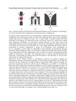
(Fig.
1.2).
To
investigate thin
film air
lubrication, some experiments were
carried
out in the
towing tank
of
MARIC
in
Shanghai, China
by the
author
and his
colleagues
in
1968,
but the
tests
verified
the
earlier results
of
Laval
and
others. Based
on
these results they
confirmed
that
a
significant
air gap was
necessary
to
separate
the
ship hull
fully
from
the
water surface. This needed
a
concave
or
tunnel hull
form.
In the mid
1950s
in the UK,
Christopher
Cockerell developed
the
idea
for
high
pressure
air jet
curtains
to
provide
a
much greater
air
gap. This invention provided
sufficient
potential
for a
prospective
new
vehicle technology that
the
British
and
later
the US
government committed large
funds
to
develop
ACV and
SES.
China
and the
USSR also supported major programmes with similar goals over
the
same period.
Air
cushion
supported
vehicles could only
be
successfully
developed
using
suitable
light
materials
for the
hull
and
engines. Initial prototypes used much experience from
aircraft
design
and
manufacture
to
achieve
the
necessary power
to
weight ratio.
Experience from amphibious aeroplanes
or flying
boats
was
particularly valuable
since
normal aircraft materials
are not
generally designed
to
resist corrosion when
Fig.
1.2
Finnish
ACV
constructed
by
Toivio Kaario
in
1935.
4
Introduction
to
hovercraft
immersed
in
salt water
an
important design parameter
for
marine vehicles.
Additionally,
it
suggested
a
number
of
alternatives
to the
basic principle
of
pumping
air
into
a
cavity under
a
hull, using
a
modified wing form instead,
to
achieve vehicles with
speeds closer
to
that
of
aircraft. Several vehicle concepts have developed
from
this work.
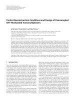
Amphibious
hovercraft
(or
ACV)
The
amphibious hovercraft (Fig. 1.3)
is
supported totally
by its air
cushion, with
an
air
curtain (high pressure jet)
or a flexible
skirt system around
its
periphery
to
seal
the
cushion air. These
craft
possess
a
shallow draft
(or a
negative draft
of the
hull struc-
ture
itself)
and
amphibious characteristics. They
are
either passive (being towed
by
other equipment)
or
active, i.e. propelled
by air
propellers
or
fans.
Some
'hybrid'
craft
have used surface stroking, balloon wheels, outboard motors
and
water jets
to
achieve
different
utility
requirements.
Fig.
1.3
First
Chinese
medium-size
amphibious
hovercraft
model
722-1.
Sidewall hovercraft
(or
SES)
This concept (Figs
1.4 and
1.5) reduces
the flexible
skirt
to a
seal
at the bow and
stern
of
a
marine (non-amphibious) craft, using walls
or
hulls
like
a
catamaran
at the
sides.
The
walls
or
hulls
at
both
sides
of the
craft,
and the
bow/stern seal installation,
are
designed
to
minimize
the
lift
power.
Due to the
lack
of air
leakage
at the
craft
sides,
lift
power
can be
reduced significantly
compared
with
an
ACV. Also,
it is
possible
to
install conventional water propellers
or
waterjet
propulsion, with rather smaller machinery
space
requirements compared
to
that
for
air
propellers
or
fans
used
on
ACVs. This more
compact
machinery arrangement,
combined with
the
possibility
for
higher cushion pressure supporting higher specific pay-
load,
has
made
a
transition
to
larger size much easier
for
this concept than
for the
ACV.
Hovercraft
beginnings
5
Fig.
1.4
Chinese passenger sidewall hovercraft model
719-1
Fig.
1.5
First
Chinese passenger
sidewall
hovercraft type,
Jin Sah
River.
Wing-in-ground
effect (WIG)
and
power
augmented
ram
wing
(PARWIG)
craft
These
craft
are
rather
different
from
the ACV or
SES. They
are
more like
low flying
aircraft,
and use
ground proximity
to
increase
lift
on the
specially
shaped
wing.
The
craft
are
supported
by
dynamic
lift
rather than
a
static cushion.
The WIG
(Fig. 1.6) initially floats
on the
water
and its
take-off
is
similar
to a
sea-
plane.
An
aeroplane wing operated close
to the
ground generates
lift
at the
pressur-
ized
surface
of the
wings which
is
increased
significantly
due to the
surface
effect.
The
aero-hydrodynamic
characteristics
of a WIG are
therefore
a
significant optimization
of
the
design
of a
seaplane
to
improve payload.
The
PARWIG shown
in
Fig.
1.7
differs
from
a WIG by the
different
location
of
lift
fans,
in
which
the
lift
fans
(or bow
thrusters)
are
located
at the bow and
beyond
the air
cushion; consequently
a
large
amount
of air can be
directly injected into
the
6
Introduction
to
hovercraft
cushion space under
the
wing
and
produce static
lift.
This gives
a
PARWIG
the
abil-
ity
to
hover through static cushion
lift
alone.
Due to the
distinct
differences
for
both
hydrodynamics
and
structural design between PAR/WIG
and
ACV/SES craft,
the
theory
and
design
of
PAR/WIG
are not
discussed
further
in
this book.
Air
cushion
craft
are
part
of the
larger group
of
high performance vehicles shown
in
Fig.
1.1,
and may be
divided
as
shown
in
Fig.
1.8
with respect
to
their operational
features,
applications,
flexible
skirt system
and
means
of
propulsion.
Fig.
1.6
Chinese
ram
wing
craft model
902.
Fig.
1.7
First
Chinese power augmented
wing
in
ground effect craft model
750.
Hovercraft
Hydrofoil Monohull Catamaran
o
n
ACV
SES
Catamaran SWATH
WIG
Fig.
1.8
Classification
of
hovercraft.
Hovercraft beginnings
7
The
work
of Sir
Christopher Cockerell resulted
in the first
successful
full
scale hov-
ercraft
to be
built
in
Europe,
the
Saunders
Roe
SR.Nl, which crossed
the
English
Channel
for the first
time
on
July
25,
1959. China began
her own
hovercraft research
in
1957
in
Harbin Shipbuilding Engineering Institute, which successfully operated
their
first
open
sea
trials with
a
plenum chamber cushion hovercraft
on the
coast
of
Port
Lu
Shun
in
July
1959.
The
principal particulars
for
both
the
Chinese
and
British
prototype hovercraft
may be
seen
in
Table
1.1.
Table
1.1
Principal
particulars
for the first
Chinese
and
British hovercraft
Craft
Name
SR.Nl
(Fig 1.9)
Craft'33'(Fig
1.10)
Nationality
Research
and
Manufacturing
Unit
Craft
Type
Craft
Weight (tonnes)
Machinery
Hull
Materials
First
Sea
Trial
Distance
England
Saunders
Roe, Cowes,
loW
Peripheral
Jet
3.4
Aviation
piston engines with
a
total
output
of
319.7
kW, 70% of
which
is
used
as
lift
power
and 30% for
propulsion
Aluminium
Alloy
English
Channel
25
nautical miles
China
Harbin
Shipbuilding Engineering
Institute,
Harbin Aeroplane
Manufactory
Plenum Chamber
4.0
Aviation piston Engines 176.4
kW for
lift
and
117.6
kW for
propulsion
Aluminium
Alloy
Port
Lu
Shun
16
nautical miles
Fig.
1.9
SR.N1
- the
first
British
ACV,
which
successfully
crossed
the
English
Channel.
Introduction
to
hovercraft
(a).
Fig.
1.10
First Chinese experimental hovercraft
(with
plenum chamber cushion) successfully operated
in
long
range
in the
coast
of
Port
Lu
Shun
in
July
1959,
(a) on
beach;
(b)
operating
at
high
speed.
Since
these
first sea
trials
for
hovercraft were
successfully
undertaken both
in
China
and
England,
the
number
of
hovercraft designed
and
built
for
both
commercial
and
military
purposes
has
exceeded 2000 world-wide, including
as
many
as
1000 Soviet
hover platforms
in the
Arctic
and oil
exploration
fields.
Thanks
to
rapidly developing
materials, engines, electronics
and
computer systems
in
recent years, hovercraft have
developed quickly
from
the
research stage into commercial
and
military applications,
(see
comparisons
with
other transport concepts
in
Table
1.2)
reaching
the
high speeds
aimed
for in
just
20
years,
a
rare achievement
in the
development
of
transport con-
cepts. Examples
of
this
are the US
SES-100B, weighing
a
hundred
tons
and
operated
at a
speed
of
90.3 knots,
and the BHC
SR.N4
ACV
which
has
achieved similar speeds
to
service across
the
English channel when lightly loaded.
Hovercraft
have
had
their
difficulties
during development
in the 60s and
70s,
in
the
same
way as
most
new
transport concepts.
The
concept
has now
matured,
and
SES in
particular
are
beginning
to be
developed
at the
size originally predicted
by
the
early pioneers: 1000 tonnes
and
larger. Although
different
approaches
have been
adopted
for
hovercraft development
in
different
countries, they have
followed
almost
the
same stages: initial research, concept development, market development
and
then
the
development stage again
to
improve economic performance
to
compete with
craft
such
as
fast
catamarans which have developed
so
rapidly since
1985.
In the
following
sections
of
Chapter
1 we
will summarise
the
development
of
ACV
and SES
development
in the UK 9
Table
1.2
Time interval
for
various military transport vehicles
from
invention
to first
application
Type
of
Vehicle
Time
Interval from invention
to first
application
(years)
Steam
boat
41
Hydrofoil
craft
35
Submarine
25
Hovercraft
13
Jet
aircraft
12
Aircraft
8
hovercraft,
focussing
on the UK,
former USSR,
USA and
China which have been
leading centres
of
both
analytical
and
practical
craft
development.
In
Britain
the
hovercraft
has
been developed mainly
for
civil applications, while
the
US
government
has
strongly supported development
for
military use,
and
only lately
has
commercial interest increased.
In
China,
the
main developments paralleled
the
UK,
beginning with prototypes
for
full
scale testing,
followed
by
commercial craft,
and
some
experimental military vehicles.
Most
ACV and SES in
China
are for
com-
mercial use.
In the
former USSR medium sized amphibious hovercraft have been
developed
for
military use,
SES for
inland river transport
and air
cushion platforms
for
oil
exploration, followed
in the
late 1970s
by
some very large military vechicles.
Less information
is
available
about
the
USSR
craft,
though
it is
clear that similar tech-
nology developed
in
parallel with
the
other three major centres described here.
While these countries have been pioneers
in the
design
and
construction
of ACV
and
SES, many
others
now
have significant
programmes.
In
Norway, large
SES
have
been developed
as
Coastal Mine Warfare vessels
and
Fast
Patrol craft.
In
Korea sig-
nificant
numbers
of
large commercial
SES and
ACVs have been built,
and in
Japan
a
large development programme
has
been carried
out
through
the
1990s
to
develop
SES
high speed short
sea
cargo vessels.
1.2
ACV
and
SES
development
in the UK
Initial
research:
before
1963
In
1953, Christopher Cockerell,
an
electronics engineer with
a
small commercial boat-
building
interest, began thinking about
the
age-old problem
of
decreasing
the
resis-
tance
to
ships' travel through
the
water. First
he
tried introducing
air films
under
model
boats
to
give
a
kind
of
lubricated
surface.
This
was not
successful
and the
next
stages towards
the
evolution
of the
hovercraft principle
are
best described
in his own
words:
After
I had
learnt from,
and
found
out the
shortcomings
of
'air-lubrication
experimentally,
the first
idea
I had was fixed
sidewalls
with hinged doors
at the
ends,
with
air
pumped into
the
centre.
The
next
idea,
at
about
the end of
1954,
was
fixed
sidewalls
with
water curtains sealing
the
ends.
I
stuck here
for a
bit,
10
Introduction
to
hovercraft
because
I
didn't know enough
to be
able
to
work
out the
probable duct
and
other
losses
and the
sort
of
power that would
be
required.
Then
one
Saturday evening
I
thought
I
would have
a
look
at
using
air
curtains.
A
simple calculation looked
all
right
on a
power basis,
and so
that Sunday
I
made
up an
annular
jet
using
two
coffee
tins,
and
found that
the air did
follow
the
'predicted'
path
and
that there
was a
'predicted'
gain
in
lift
-
very
exiting.
Cockerell secured
the
assistance
of a
fellow
boatbuilder
in
constructing
a
working
model
of the
type
of
craft envisaged. This
was
used
as a
test model
for
several years
and is now in the
Science Museum
in
London.
In
December 1955 Cockerell applied
for
his first
British patent covering
lift
by
means
of
peripheral annular jets.
Until 1956,
air
cushion technology
was
considered
to
have military potential
and
was
put on the
list
of
projects which
had
public information restrictions when
it was
offered
to the
British Government
for
development sponsorship
by Sir
Christopher
Cockerell.
At
this time, study
was
centred
on
investigation using
free
flying
models.
For the
next
two
years
he
made
the
rounds
of
industry
and
government departments
with remarkably little
to
show
for it. The
shipbuilding
firms
said
'It's
not a
ship
- try
the
aircraft
industry',
and the
aircraft
firms
said
'It's
not an
aircraft
- try the
ship-
builders'.
Three
engine manufacturers said
'Not
for us, but if you
want your invention
taken
up,
remember
to use our
engines'. However,
he did
receive valuable encourage-
ment from
Mr R. A.
Shaw
of the
Ministry
of
Supply,
and
eventually during 1957
the
Ministry
approached
Saunders-Roe
who
accepted
a
contract
to
undertake
a
feasibil-
ity
study
and to do
model tests.
The
Saunders-Roe design team
who
undertook this initial study also formed
the
nucleus
of
British Hovercraft Corporation's technical
staff
later
in the
1960s. Prior
to
involvement
with
hovercraft
they
had for
many years been engaged
in the
design
and
construction
of flying
boats
and
hydrofoils.
It was
precisely because
of
this background
of
'fish
and
fowl'
expertise that
the
hovercraft principle
was
enthusiastically pursued.
Christopher Cockerell
in the
meantime
had
approached
the
National
Research
Development Corporation
(N.R.D.C.)
who
also realised
that
hovercraft were likely
to
became
a
revolutionary
new
form
of
transport
and
through them,
a
subsidiary
Company known
as
Hovercraft Development Limited
(H.D.L.)
was set up in
January
1958
with Cockerell leading
the
research group
as
Technical
Director.
The
report
of the
Saunders-Roe feasibility study
was
favourable,
as a
result
of
which
N.R.D.C.
placed
a
further contract with
the
company
for a
programme
of
work
which included
the
design
and
manufacture
of a
manned development craft desig-
nated SR.N1 (Fig.
1.9).
This historic craft
was
completed
on
28th
May
1959.
On
July
25th 1959,
in its
original form,
it
crossed
the
English Channel from Calais
to
Dover
with Christopher Cockerell
on
board
to
mark
the
50th anniversary
of the first
cross-
channel
flight by
Bleriot
in an
aeroplane.
Although
the first
cross channel operations
on
relatively calm water were very suc-
cessful,
the
craft performance, manoeuvrability, seakeeping quality
and
propulsion
efficiency
were very
poor.
The
craft
had an air gap
over
the
ground
of
about
100
mm
whilst
the
lift
power,
at
about 36.7 kW/t,
was
rather high.
The
efficiency
of the air jet
propulsion
used
was
low,
and
manoeuvrability
was so
poor
that
the
pilot
was
unable
to
handle
the
craft
in a
stable manner.
The
SR.N1
was
built
in an
aviation factory,
and
aviation engines, equipment, structures
and
construction technology were used.
For