Robot Manipulator Control Theory and Practice Second Edition, Revised and Expanded doc
Bạn đang xem bản rút gọn của tài liệu. Xem và tải ngay bản đầy đủ của tài liệu tại đây (10.97 MB, 614 trang )
Robot
Manipulator
Control
Theory and Practice
Second Edition, Revised and Expanded
Copyright © 2004 by Marcel Dekker, Inc.
CONTROL ENGINEERING
A Series of Reference Books and Textbooks
Editors
NEIL MUNRO, PH.D., D.SC.
Professor
Applied Control Engineering
University of Manchester Institute of Science and Technology
Manchester, United Kingdom
FRANK L.LEWIS, PH.D.
Moncrief-O’Donnell Endowed Chair
and Associate Director of Research
Automation & Robotics Research Institute
University of Texas, Arlington
1. Nonlinear Control of Electric Machinery, Darren M.Dawson, Jun Hu,
and Timothy C.Burg
2. Computational Intelligence in Control Engineering, Robert E.King
3. Quantitative Feedback Theory: Fundamentals and Applications,
Constantine H.Houpis and Steven J.Rasmussen
4. Self-Learning Control of Finite Markov Chains, A.S.Poznyak, K.Najlm,
and E.Gómez-Ramírez
5. Robust Control and Filtering for Time-Delay Systems, Magdi
S.Mahmoud
6. Classical Feedback Control: With MATLAB, Boris J.Lurie and Paul J.
Enright
7. Optimal Control of Singularly Perturbed Linear Systems and
Applications: High-Accuracy Techniques, Zoran Gajic and Myo-Taeg
Lim
8. Engineering System Dynamics: A Unified Graph-Centered Approach,
Forbes T.Brown
9. Advanced Process Identification and Control, Enso Ikonen and Kaddour
Najim
10. Modern Control Engineering, P.N.Paraskevopoulos
11. Sliding Mode Control in Engineering, edited by Wilfrid Perruquetti and
Jean Pierre Barbot
12. Actuator Saturation Control, edited by Vikram Kapila and Karolos M.
Grigoriadis
Copyright © 2004 by Marcel Dekker, Inc.
13. Nonlinear Control Systems, Zoran Vukic, Ljubomir Kuljaca, Dali
Donlagic,Sejid Tešnjak
14. Linear Control System Analysis and Design with MATLAB: Fifth Edition,
Revised and Expanded, John J.D’Azzo, Constantine H.Houpis, and
Stuart N.Sheldon
15. Robot Manipulator Control: Theory and Practice, Second Edition,
Revised and Expanded, Frank L.Lewis, Darren M.Dawson, and Chaouki
T.Abdallah
16. Robust Control System Design: Advanced State Space Techniques,
Second Edition, Revised and Expanded, Chia-Chi Tsui
Additional Volumes in Preparation
Copyright © 2004 by Marcel Dekker, Inc.
Frank L.Lewis
University of Texas at Arlington
Arlington, Texas, U.S.A.
Darren M.Dawson
Clemson University
Clemson, South Carolina, U.S.A.
Chaouki T.Abdallah
University of New Mexico
Albuquerque, New Mexico, U.S.A.
MARCEL DEKKER, INC. NEW YORK • BASEL
Robot
Manipulator
Control
Theory and Practice
Second Edition, Revised and Expanded
Copyright © 2004 by Marcel Dekker, Inc.
First edition: Control of Robot Manipulators, FL Lewis, CT Abdallah, DM Dawson,
1993. This book was previously published by Prentice-Hall, Inc.
Although great care has been taken to provide accurate and current information,
neither the author(s) nor the publisher, nor anyone else associated with this publication,
shall be liable for any loss, damage, or liability directly or indirectly caused or alleged
to be caused by this book. The material contained herein is not intended to provide
specific advice or recommendations for any specific situation.
Trademark notice: Product or corporate names may be trademarks or registered
trademarks and are used only for identification and explanation without intent to
infringe.
Library of Congress Cataloging-in-Publication Data
A catalog record for this book is available from the Library of Congress.
ISBN: 0-8247-4072-6
Transferred to Digital Printing 2006
Headquarters
Marcel Dekker, Inc., 270 Madison Avenue, New York, NY 10016, U.S.A.
tel: 212–696–9000; fax: 212–685–4540
Distribution and Customer Service
Marcel Dekker, Inc., Cimarron Road, Monticello, New York 12701, U.S.A.
tel: 800–228–1160; fax: 845–796–1772
Eastern Hemisphere Distribution
Marcel Dekker AG, Hutgasse 4, Postfach 812, CH-4001 Basel, Switzerland
tel: 41–61–260–6300; fax: 41–61–260–6333
World Wide Web
The publisher offers discounts on this book when ordered in bulk quantities. For
more information, write to Special Sales/Professional Marketing at the headquarters
address above.
Copyright © 2004 by Marcel Dekker, Inc. All Rights Reserved.
Neither this book nor any part may be reproduced or transmitted in any form or by
any means, electronic or mechanical, including photocopying, microfilming, and
recording, or by any information storage and retrieval system, without permission in
writing from the publisher.
Publisher’s Note
The publisher has gone to great
lengths to ensurethe quality of this reprint but
points out that some imperfectionsin the original may be apparent
Copyright © 2004 by Marcel Dekker, Inc.
To My Sons Christopher and Roman
F.L.L.
To My Faithful Wife, Dr. Kim Dawson
D.M.D.
To My 3 C’s
C.T.A.
Copyright © 2004 by Marcel Dekker, Inc.
v
Series Introduction
Many textbooks have been written on control engineering, describing new
techniques for controlling systems, or new and better ways of mathematically
formulating existing methods to solve the ever-increasing complex problems
faced by practicing engineers. However, few of these books fully address the
applications aspects of control engineering. It is the intention of this new
series to redress this situation.
The series will stress applications issues, and not just the mathematics of
control engineering. It will provide texts that present not only both new and
well-established techniques, but also detailed examples of the application of
these methods to the solution of real-world problems. The authors will be
drawn from both the academic world and the relevant applications sectors.
There are already many exciting examples of the application of control
techniques in the established fields of electrical, mechanical (including
aerospace), and chemical engineering. We have only to look around in today’s
highly automated society to see the use of advanced robotics techniques in
the manufacturing industries; the use of automated control and navigation
systems in air and surface transport systems; the increasing use of intelligent
control systems in the many artifacts available to the domestic consumer
market; and the reliable supply of water, gas, and electrical power to the
domestic consumer and to industry. However, there are currently many
challenging problems that could benefit from wider exposure to the
applicability of control methodologies, and the systematic systems-oriented
basis inherent in the application of control techniques.
This series presents books that draw on expertise from both the academic
world and the applications domains, and will be useful not only as
academically recommended course texts but also as handbooks for
practitioners in many applications domains. Nonlinear Control Systems is
another outstanding entry in Dekker’s Control Engineering series.
Copyright © 2004 by Marcel Dekker, Inc.
vii
Preface
The word ‘robot’ was introduced by the Czech playwright Karel Capek in
his 1920 play Rossum’s Universal Robots. The word ‘robota’ in Czech
means simply ‘work’. In spite of such practical beginnings, science fiction
writers and early Hollywood movies have given us a romantic notion of
robots. The anthropomorphic nature of these machines seems to have
introduced into the notion of robot some element of man’s search for his
own identity.
The word ‘automation’ was introduced in the 1940’s at the Ford Motor
Company, a contraction for ‘automatic motivation’. The single term
‘automation’ brings together two ideas: the notion of special purpose robotic
machines designed to mechanically perform tasks, and the notion of an
automatic control system to direct them.
The history of automatic control systems has deep roots. Most of the
feedback controllers of the Greeks and Arabs regulated water clocks for the
accurate telling of time; these were made obsolete by the invention of the
mechanical clock in Switzerland in the fourteenth century. Automatic control
systems only came into their own three hundred years later during the
industrial revolution with the advent of machines sophisticated enough to
require advanced controllers; we have in mind especially the windmill and
the steam engine. On the other hand, though invented by others (e.g.
T.Newcomen in 1712) the credit for the steam engine is usually assigned to
James Watt, who in 1769 produced his engine which combined mechanical
innovations with a control system that allowed automatic regulation. That
is, modern complex machines are not useful unless equipped with a suitable
control system.
Watt’s centrifugal fly ball governor in 1788 provided a constant speed
controller, allowing efficient use of the steam engine in industry. The motion
of the flyball governor is clearly visible even to the untrained eye, and its
principle had an exotic flavor that seemed to many to embody the spirit of
Copyright © 2004 by Marcel Dekker, Inc.
PREFACEviii
the new age. Consequently the governor quickly became a sensation
throughout Europe.
Master-slave telerobotic mechanisms were used in the mid 1940’s at Oak
Ridge and Argonne National Laboratories for remote handling of radioactive
material. The first commercially available robot was marketed in the late
1950’s by Unimation (nearly coincidentally with Sputnik in 1957-thus the
space age and the age of robots began simultaneously). Like the flyball
governor, the motion of a robot manipulator is evident even for the untrained
eye, so that the potential of robotic devices can capture the imagination.
However, the high hopes of the 1960’s for autonomous robotic automation
in industry and unstructured environments have generally failed to materialize.
This is because robotics today is at the same stage as the steam engine was
shortly after the work of Newcomen in 1712.
Robotics is an interdisciplinary field involving diverse disciplines such as
physics, mechanical design, statics and dynamics, electronics, control theory,
sensors, vision, signal processing, computer programming, artificial
intelligence (AI), and manufacturing. Various specialists study various limited
aspects of robotics, but few engineers are able to confront all these areas
simultaneously. This further contributes to the romanticized nature of
robotics, for the control theorist, for instance, has a quixotic and fanciful
notion of AI.
We might break robotics into five major areas: motion control, sensors
and vision, planning and coordination, AI and decision-making, and
manmachine interface. Without a good control system, a robotic device is
useless. The robot arm plus its control system can be encapsulated as a
generalized data abstraction; that is, robot-plus-controller is considered a
single entity, or ‘agent’, for interaction with the external world.
The capabilities of the robotic agent are determined by the mechanical
precision of motion and force exertion capabilities, the number of degrees of
freedom of the arm, the degree of manipulability of the gripper, the sensors,
and the sophistication and reliability of the controller. The inputs for a robot
arm are simply motor currents and voltages, or hydraulic or pneumatic
pressures; however, the inputs for the robot-plus-controller agent can be
desired trajectories of motion, or desired exerted forces. Thus, the control
system lifts the robot up a level in a hierarchy of abstraction.
This book is intended to provide an in-depth study of control systems
for serial-link robot arms. It is a revised and expended version of our 1993
book. Chapters have been added on commercial robot manipulators and
devices, neural network intelligent control, and implementation of advanced
controllers on actual robotic systems. Chapter 1 places this book in the
context of existing commercial robotic systems by describing the robots
that are available and their limitations and capabilities, sensors, and
controllers.
Copyright © 2004 by Marcel Dekker, Inc.
PREFACE ix
We wanted this book to be suitable either for the controls engineer or the
roboticist. Therefore, Appendix A provides a background in robot kine-
matics and Jacobians, and Chapter 2 a background in control theory and
mathematical notions. The intent was to furnish a text for a second course
in robotics at the graduate level, but given the background material it is used
at UTA as a first year graduate course for electrical engineering students.
This course was also listed as part of the undergraduate curriculum, and the
undergraduate students quickly digested the material.
Chapter 3 introduces the robot dynamical equations needed as the basis
for controls design. In Appendix C and examples throughout the book are
given the dynamics of some common arms. Chapter 4 covers the essential
topic of computed-torque control, which gives important insight while also
bringing together in a unified framework several sorts of classical and modern
robot control schemes.
Robust and adaptive control are covered in Chapters 5 and 6 in a parallel
fashion to bring out the similarities and the differences of these two
approaches to control in the face of uncertainties and disturbances. Chapter
7 addresses some advanced techniques including learning control and arms
with flexible joint coupling.
Modern intelligent control techniques based on biological systems have
solved many problems in the control of complex systems, including unknown
non-parametrizable dynamics and unknown disturbances, backlash, friction,
and deadzone. Therefore, we have added a chapter on neural network control
systems as Chapter 8. A robot is only useful if it comes in contact with its
environment, so that force control issues are treated in Chapter 9.
A key to the verification of successful controller design is computer
simulation. Therefore, we address computer simulation of controlled
nonlinear systems and illustrate the procedure in examples throughout the
text. Simulation software is given in Appendix B. Commercially available
packages such as MATLAB make it very easy to simulate robot control
systems.
Having designed a robot control system it is necessary to implement it;
given today’s microprocessors and digital signal processors, it is a short step
from computer simulation to implementation, since the controller subroutines
needed for simulation, and contained in the book, are virtually identical to
those needed in a microprocessor for implementation on an actual arm. In
fact, Chapter 10 shows the techniques for implementing the advanced
controllers developed in this book on actual robotics systems.
All essential information and controls design algorithms are displayed in
tables in the book. This, along with the List of Examples and List of Tables
at the beginning of the book make for convenient reference by the student,
the academician, or the practicing engineer.
We thank Wei Cheng of Milagro Design for her L
A
T
E
Xtypesetting and
Copyright © 2004 by Marcel Dekker, Inc.
PREFACEx
figure preparation as well as her scanning in the contents from the first edition
into electronic format.
F.L.Lewis, Arlington, Texas
D.M.Dawson, Clemson, South Carolina
C.T.Abdallah, Albuquerque, New Mexico
Copyright © 2004 by Marcel Dekker, Inc.
xi
Contents
Series Introduction v
Preface vii
1 Commercial Robot Manipulators 1
1.1 Introduction 1
Flexible Robotic Workcells 2
1.2 Commercial Robot Configurations and Types 3
Manipulator Performance 3
Common Kinematic Configurations 4
Drive Types of Commercial Robots 9
1.3 Commercial Robot Controllers 10
1.4 Sensors 12
Types of Sensors 13
Sensor Data Processing 16
References 19
2 Introduction to Control Theory 21
2.1 Introduction 21
2.2 Linear State-Variable Systems 22
Continuous-Time Systems 22
Discrete-Time Systems 28
2.3 Nonlinear State-Variable Systems 31
Continuous-Time Systems 31
Discrete-Time Systems 35
2.4 Nonlinear Systems and Equilibrium Points 36
2.5 Vector Spaces, Norms, and Inner Products 39
Copyright © 2004 by Marcel Dekker, Inc.
CONTENTSxii
Linear Vector Spaces 39
Norms of Signals and Systems 40
Inner Products 48
Matrix Properties 48
2.6 Stability Theory 51
2.7 Lyapunov Stability Theorems 67
Functions Of Class K 67
Lyapunov Theorems 69
The Autonomous Case 72
2.8 Input/Output Stability 80
2.9 Advanced Stability Results 82
Passive Systems 82
Positive-Real Systems 84
Lure’s Problem 85
The MKY Lemma 86
2.10 Useful Theorems and Lemmas 88
Small-Gain Theorem 88
Total Stability Theorem 89
2.11 Linear Controller Design 93
2.12 Summary and Notes 101
References 103
3 Robot Dynamics 107
3.1 Introduction 107
3.2 Lagrange-Euler Dynamics 108
Force, Inertia, and Energy 108
Lagrange’s Equations of Motion 111
Derivation of Manipulator Dynamics 119
3.3 Structure and Properties of the Robot Equation 125
Properties of the Inertia Matrix 126
Properties of the Coriolis/Centripetal Term 127
Properties of the Gravity, Friction,
and Disturbance 134
Linearity in the Parameters 136
Passivity and Conservation of Energy 141
3.4 State-Variable Representations and Feedback Linearization 142
Hamiltonian Formulation 143
Position/Velocity Formulations 145
Feedback Linearization 145
3.5 Cartesian and Other Dynamics 148
Cartesian Arm Dynamics 148
Copyright © 2004 by Marcel Dekker, Inc.
CONTENTS xiii
Structure and Properties of the Cartesian
Dynamics 150
3.6 Actuator Dynamics 152
Dynamics of a Robot Arm with Actuators 152
Third-Order Arm-Plus-Actuator Dynamics 154
Dynamics with Joint Flexibility 155
3.7 Summary 161
References 163
Problems 166
4 Computed-Torque Control 169
4.1 Introduction 169
4.2 Path Generation 170
Converting Cartesian Trajectories to Joint Space 171
Polynomial Path Interpolation 173
Linear Function with Parabolic Blends 176
Minimum-Time Trajectories 178
4.3 Computer Simulation of Robotic Systems 181
Simulation of Robot Dynamics 181
Simulation of Digital Robot Controllers 182
4.4 Computed-Torque Control 185
Derivation of Inner Feedforward Loop 185
PD Outer-Loop Design 188
PID Outer-Loop Design 197
Class of Computed-Torque-Like Controllers 202
PD-Plus-Gravity Controller 205
Classical Joint Control 208
4.5 Digital Robot Control 222
Guaranteed Performance on Sampling 224
Discretization of Inner Nonlinear Loop 225
Joint Velocity Estimates from Position
Measurements 226
Discretization of Outer PD/PID Control Loop 226
Actuator Saturation and Integrator Antiwindup
Compensation 228
4.6 Optimal Outer-Loop Design 243
Linear Quadratic Optimal Control 243
Linear Quadratic Computed-Torque Design 246
4.7 Cartesian Control 248
Cartesian Computed-Torque Control 248
Cartesian Error Computation 250
4.8 Summary 251
Copyright © 2004 by Marcel Dekker, Inc.
CONTENTSxiv
References 253
Problems 257
5 Robust Control of Robotic Manipulators 263
5.1 Introduction 263
5.2 Feedback-Linearization Controllers 265
Lyapunov Designs 268
Input-Output Designs 273
5.3 Nonlinear Controllers 293
Direct Passive Controllers 293
Variable-Structure Controllers 297
Saturation-Type Controllers 306
5.4 Dynamics Redesign 316
Decoupled Designs 316
Imaginary Robot Concept 318
5.5 Summary 320
References 321
Problems 324
6 Adaptive Control of Robotic Manipulators 329
6.1 Introduction 329
6.2 Adaptive Control by a Computed-Torque Approach 330
Approximate Computed-Torque Controller 330
Adaptive Computed-Torque Controller 333
6.3 Adaptive Control by an Inertia-Related Approach 341
Examination of a PD Plus Gravity Controller 343
Adaptive Inertia-Related Controller 344
6.4 Adaptive Controllers Based on Passivity 349
Passive Adaptive Controller 349
General Adaptive Update Rule 356
6.5 Persistency of Excitation 357
6.6 Composite Adaptive Controller 361
Torque Filtering 362
Least-Squares Estimation 365
Composite Adaptive Controller 368
6.7 Robustness of Adaptive Controllers 371
Torque-Based Disturbance Rejection Method 372
Estimator-Based Disturbance Rejection Method 375
6.8 Summary 377
References 379
Problems 381
Copyright © 2004 by Marcel Dekker, Inc.
CONTENTS xv
7 Advanced Control Techniques 383
7.1 Introduction 383
7.2 Robot Controllers with Reduced On-Line Computation 384
Desired Compensation Adaptation Law 384
Repetitive Control Law 392
7.3 Adaptive Robust Control 399
7.4 Compensation for Actuator Dynamics 407
Electrical Dynamics 408
Joint Flexibilities 416
7.5 Summary 426
References 427
Problems 429
8 Neural Network Control of Robots 431
8.1 Introduction 431
8.2 Background in Neural Networks 433
Multilayer Neural Networks 433
Linear-in-the-parameter neural nets 437
8.3 Tracking Control Using Static Neural Networks 440
Robot Arm Dynamics and Error System 440
Adaptive Control 442
Neural Net Feedback Tracking Controller 443
8.4 Tuning Algorithms for Linear-in-the-Parameters NN 445
8.5 Tuning Algorithms for Nonlinear-in-the-Parameters NN 449
Passivity Properties of NN Controllers 453
Passivity of the Robot Tracking Error Dynamics 453
Passivity Properties of 2-layer NN Controllers 455
Passivity Properties of 1-Layer NN Controllers 458
8.6 Summary 458
References 459
9 Force Control 463
9.1 Introduction 463
9.2 Stiffness Control 464
Stiffness Control of a Single-Degree-of-Freedom
Manipulator 464
The Jacobian Matrix and Environmental Forces 467
Stiffness Control of an N-Link Manipulator 474
9.3 Hybrid Position/Force Control 478
Hybrid Position/Force Control of a Cartesian
Two-Link Arm 479
Copyright © 2004 by Marcel Dekker, Inc.
CONTENTSxvi
Hybrid Position/Force Control of an N-Link
Manipulator 482
Implementation Issues 487
9.4 Hybrid Impedance Control 489
Modeling the Environment 490
Position and Force Control Models 492
Impedance Control Formulation 494
Implementation Issues 499
9.5 Reduced State Position/Force Control 501
Effects of Holonomic Constraints on the
Manipulator Dynamics 501
Reduced State Modeling and Control 504
Implementation Issues 509
9.6 Summary 510
References 513
Problems 514
10 Robot Control Implementation and Software 517
10.1 Introduction 518
10.2 Tools and Technologies 520
10.3 Design of the Robotic Platform 523
Overview 523
Core Classes 526
Robot Control Classes 527
External Device Classes 532
Utility Classes 533
Configuration Management 533
Object Manager 534
Concurrency/Communication Model 537
Plotting and Control Tuning Capabilities 538
Math Library 540
Error Management and the Front-End GUI 542
10.4 Operation of the Robotic Platform 543
Scene Viewer and Control Panels 543
Utility Programs for Moving the Robot 544
Writing, Compiling, Linking, and Starting
Control Programs 545
10.5 Programming Examples 548
Comparison of Simulation and Implementation 548
Virtual Walls 548
10.6 Summary 550
References 551
Copyright © 2004 by Marcel Dekker, Inc.
CONTENTS xvii
A Review of Robot Kinematics and Jacobians 555
A.1 Basic Manipulator Geometries 555
A.2 Robot Kinematics 558
A.3 The Manipulator Jacobian 576
References 589
B Software for Controller Simulation 591
References 597
C Dynamics of Some Common Robot Arms 599
C.1 SCARA ARM 600
C.2 Stanford Manipulator 601
C.3 PUMA 560 Manipulator 603
References 607
Copyright © 2004 by Marcel Dekker, Inc.
1
Chapter 1
Commercial Robot
Manipulators
This chapter sets the stage for this book by providing an overview of
commercially available robotic manipulators, sensors, and controllers. We
make the point that if one desires high performance flexible robotic workcells,
then it is necessary to design advanced control systems for robot manipulators
such as are found in this book.
1.1 Introduction
When studying advanced techniques for robot control, planning, sensors,
and human interfacing, it is important to be aware of the systems that are
commercially available. This allows one to develop new technology in the
context of existing technology, which allows one to implement the new
techniques on existing robotic systems.
A National Association of Manufacturer’s report [NAM 1998] states that
the two most important drivers for US commercial business manufacturing
success in the 1990’s have been reconfigurable manufacturing workcells and
local area networks in the factory. In this chapter we discuss flexible robotic
workcells, commercial robot configurations, commercial robot controllers,
information integration to the internet, and robot workcell sensors. More
information on these topics can be found in the Mechanical Engineering
Handbook [Lewis 1998] and the Computer Science Engineering Handbook
[Lewis and Fitzgerald 1997].
Copyright © 2004 by Marcel Dekker, Inc.
Commercial Robot Manipulators2
Flexible Robotic Workcells
In factory automation and elsewhere it was once common to use fixed
layouts built around conveyors or other transportation systems in which
each robot performed a specific task. These assembly lines had distinct
workstations, each performing a dedicated function. Robots have been
used at the workstation level to perform operations such as assembly,
drilling, surface finishing, welding, palletizing, and so on. In the assembly
line, parts are routed sequentially to the workstations by the transport
system. Such systems are very expensive to install, require a cadre of
engineering experts to design and program, and are extremely difficult to
modify or reprogram as needs change. In today’s high-mix low-volume
(HMLV) manufacturing scenario, these characteristics tolled the death knell
for such rigid antiquated designs.
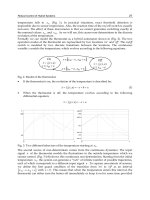
Figure 1.1.1: UTA’s Automation and Robotics Test Cell.
In the assembly line, the robot is restricted by placing it into a rigid
sequential system. Robots are versatile machines with many capabilities,
and their potential can be significantly increased by using them as a basis
for flexible robotic workcells [Decelle 1988], [Jamshidi et al. 1992], [Pugh
1983] such as the UTA Automation and Robotics Test Cell in Figure 1.1.1.
In the flexible robotic workcell, robots are used for part handling, assembly,
and other process operations. By reprogramming the robots one changes the
entire functionality of the workcell. The workcell is designed to make full
use of the workspace of the robots, and components such as milling machines,
drilling machines, vibratory part feeders, and so on are placed within the
robots’ workspaces to allow servicing by the robots. Contrary to the assembly
line, the physical layout does not impose a priori a fixed sequencing of the
operations or jobs. Thus, as product requirements change, all that is required
is to reprogram the workcell in software [Mireles and Lewis 2001]. The
Copyright © 2004 by Marcel Dekker, Inc.
3
workcell is ideally suited to emerging HMLV conditions in manufacturing
and elsewhere.
The rising popularity of robotic workcells has taken emphasis away from
hardware design and placed new emphasis on innovative software techniques
and architectures that include planning, coordination, and control (PC&C)
functions. A great deal of research into robot controllers has been required
to give robots the flexibility, precision, and functionality needed in modern
flexible workcells. The remainder of this book details such advanced control
techniques.
1.2 Commercial Robot Configurations and Types
Much of the information in this section was prepared by Mick Fitzgerald,
who was then Manager at UTA’s Automation and Robotics Research Institute
(ARRI).
Robots are highly reliable, dependable and technologically advanced
factory equipment. The majority of the world’s robots are supplied by
established companies using reliable off-the-shelf component technologies.
All commercial industrial robots have two physically separate basic
elements—the manipulator arm and the controller. The basic architecture of
most commercial robots is fundamentally the same, and consists of digital
servocontrolled electrical motor drives on serial-link kinematic machines,
usually with no more than six axes (degrees of freedom). All are supplied
with a proprietary controller. Virtually all robot applications require
significant design and implementation effort by engineers and technicians.
What makes each robot unique is how the components are put together to
achieve performance that yields a competitive product. The most important
considerations in the application of an industrial robot center on two issues:
manipulation and integration.
Manipulator Performance
The combined effects of kinematic structure, axis drive mechanism design,
and real-time motion control determine the major manipulation performance
characteristics: reach and dexterity, pay load, quickness, and precision.
Caution must be used when making decisions and comparisons based on
manufacturers’ published performance specifications because the methods
for measuring and reporting them are not standardized across the industry.
Usually motion testing, simulations, or other analysis techniques are used to
verify performance for each application.
Reach is characterized by measuring the extent of the workspace described
by the robot motion and dexterity by the angular displacement of the
1.2 Commercial Robot Configurations and Types
Copyright © 2004 by Marcel Dekker, Inc.
Commercial Robot Manipulators4
individual joints. Some robots will have unusable spaces such as dead zones,
singular poses, and wrist-wrap poses inside of the boundaries of their reach.
Payload weight is specified by the manufacturers of all industrial robots.
Some manufacturers also specify inertial loading for rotational wrist axes. It
is common for the payload to be given for extreme velocity and reach
conditions. Weight and inertia of all tooling, workpieces, cables and hoses
must be included as part of the payload.
Quickness is critical in determining throughput but difficult to determine
from published robot specifications. Most manufacturers will specify a
maximum speed of either individual joints or for a specific kinematic tool
point. However, average speed in a working cycle is the quickness
characteristic of interest.
Precision is usually characterized by measuring repeatability. Virtually
all robot manufacturers specify static position repeatability. Accuracy is
rarely specified, but it is likely to be at least four times larger than
repeatability. Dynamic precision, or the repeatability and accuracy in
tracking position, velocity, and acceleration over a continuous path, is not
usually specified.
Common Kinematic Configurations
All common commercial industrial robots are serial-link manipulators,
usually with no more than six kinematically coupled axes of motion. By
convention, the axes of motion are numbered in sequence as they are
encountered from the base on out to the wrist. The first three axes account
for the spatial positioning motion of the robot; their configuration
determines the shape of the space through which the robot can be positioned.
Any subsequent axes in the kinematic chain generally provide rotational
motions to orient the end of the robot arm and are referred to as wrist
axes. In a robotic wrist, three axes usually intersect to generate true
kinematic analysis of the spherical robot wrist mechanism. Note that in
our 3-dimensional space, one requires three degrees of freedom for fully
independent spatial positioning and three degrees of freedom for fully
independent orientational positioning.
There are two primary types of motion that a robot axis can produce
in its driven link- either revolute or prismatic. Revolute joints are
anthropomorphic (e.g. like human joints) while prismatic joints are able
to extend and retract like a car radio antenna. It is often useful to classify
robots according to the orientation and type of their first three axes.
There are four very common commercial robot configurations:
Articulated, Type I SCARA, Type II SCARA, and Cartesian. Two other
configurations, Cylindrical and Spherical, are now much less common.
Copyright © 2004 by Marcel Dekker, Inc.
independent positioning in terms of 3-D orientation. See Appendix A for a
5
Appendix C contains the dynamics of some common robot manipulators
for use in controls simulation in this book.
Figure 1.2.1: Articulated Arm. Six-axis CRS A465 arm (courtesy of CRS
robotics).
Figure 1.2.2: Type I SCARA Arm. High precision, high speed midsized SCARA I.
(courtesy of Adept Technologies, Inc.).
1.2 Commercial Robot Configurations and Types
Copyright © 2004 by Marcel Dekker, Inc.
Commercial Robot Manipulators6
Articulated Arms. The variety of commercial articulated arms, most of
are re volute. The second and third axes are co-planar and work together
to produce motion in a vertical plane. The first axis in the base is vertical
and revolves the arm to sweep out a large work volume. Many different
types of drive mechanisms have been devised to allow wrist and forearm
drive motors and gearboxes to be mounted close to the first and second
axis of rotation, thus minimizing the extended mass of the arm. The
workspace efficiency of well designed articulated arms, which is the degree
of quick dexterous reach with respect to arm size, is unsurpassed by other
arm configurations when five or more degrees of freedom are needed. A
major limiting factor in articulated arm performance is that the second
axis has to work to lift both the subsequent arm structure and the pay
load. Historically, articulated arms have not been capable of achieving
accuracy as high as other arm configurations, as all axes have joint angle
position errors which are multiplied by link radius and accumulated for
the entire arm.
Type I SCARA. The Type I SCARA (selectively compliant assembly robot
in the horizontal plane. The arm structure is weight-bearing but the first and
second axes do no lifting. The third axis of the Type I SCARA provides work
volume by adding a vertical or z axis. A fourth revolute axis will add rotation
about the z axis to control orientation in the horizontal plane. This type of
robot is rarely found with more than four axes. The Type I SCARA is used
extensively in the assembly of electronic components and devices, and it is
used broadly for the assembly of small- and mediumsized mechanical
assemblies.
configuration, differs from Type I in that the first axis is a long vertical
prismatic z stroke which lifts the two parallel revolute axis and their links.
For quickly moving heavier loads (over approximately 75 pounds) over longer
distance (more than about three feet), the Type II SCARA configuration is
more efficient than the Type I.
Cartesian Coordinate Robots. Cartesian coordinate robots use orthogonal
prismatic axes, usually referred to as x, y, and z, to translate their end-effector
or payload through their rectangular workspace. One, two, or three revolute
wrist axes may be added for orientation. Commercial robot companies supply
several types of Cartesian coordinate robots with workspace sizes ranging
from a few cubic inches to tens of thousands of cubic feet, and payloads
ranging to several hundred pounds. Gantry robots, which have an elevated
bridge structure, are the most common Cartesian style and are well suited to
Copyright © 2004 by Marcel Dekker, Inc.
which have six axes, is very large (Fig. 1.2.1). All of these robots’ axes
arm) arm, Figure 1.2.2, uses two parallel revolute joints to produce motion
Type II SCARA. The Type II SCARA, Figure 1.2.3, also a four axis
7
material handling applications where large areas and/or large loads must be
serviced. They are particularly useful in applications such as arc welding,
waterjet cutting, and inspection of large complex precision parts.
Modular Cartesian robots, see Figure 1.2.4, are also commonly available
from several commercial sources. Each module is a self-contained completely
Figure 1.2.3: Type II SCARA (courtesy of Adept Technologies, Inc.).
Figure 1.2.4: Cartesian Robot. Three-axis robot constructed from modular single-
axis motion modules (courtesy of Adept Technologies, Inc.).
1.2 Commercial Robot Configurations and Types
Copyright © 2004 by Marcel Dekker, Inc.