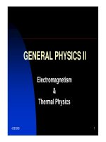
The Integrated Calorimetry Environment of CDF2 pdf
Bạn đang xem bản rút gọn của tài liệu. Xem và tải ngay bản đầy đủ của tài liệu tại đây (1.81 MB, 19 trang )
The Integrated
The Integrated
Calorimetry
Calorimetry
Environment
Environment
of CDF2
of CDF2
Robin Erbacher / The CDF Collaboration
Fermilab Batavia, Illinois U.S.A.
ICHEP: 31
st
International Conference on High Energy Physics
Amsterdam, Netherlands July 24-31, 2002
2
Calorimeter Integration
¾Various Tevatron upgrades required
changes to system, enabling integration:
•√s: 1.8 → 1.96 TeV (PMT signals double)
•Bunch Xing: 3.5 µs → 132 ns (new FEE/trigger)
•Lum: 2x10
31
cm
-2
s
-1
(’96) → 5x10
32
(>’04)
¾Replacement of old gas plug calorimeters
•Rate limitations at Tevatron Run 2
•Forward noisy due to insufficient shielding
•Unlike in the central, no EM pre-shower and
no timing measurement.
3
Wall Had
New Plug Had
Central Had
Central EM
New Plug EM
New Silicon
|η| < 2.0
New Drift
Chamber
CDF2
Smaller
fwd gap
4
The CDF2 Calorimeter System
New Plug Calorimeter
Endwall Calorimeter
Rack for Central and
Endwall Electronics
5
EndPlug Upgrade
¾Central Calorimeters
•Kept Run I detectors
•Scintillator based→fast
•New readout electronics
¾New Plug Calorimeters
•Scintillator tile design: Fast !
plus better sampling fraction
than Run I gas detector
•Same technology over full
solid angle to |η| = 3.6
•More hermetic: 10
o
fwd
gap gone, 30
o
reduced
6
Similar Technology Across η
¾All calorimeters now use
scintillators plus WLS:
•Central: plastic slab with
lead/steel and WLS
•Plug: scintillator tile with
lead/steel and WLS
0.1
0.1
0.16
0.2-0.6
15
o
7.5
o
7.5
o
15
o
0 1.2
1.2-1.8
1.8-2.1
2.1-3.6
∆η
Size
∆φ
size
|η|
range
SEGMENTATION OF THE
“PROJECTIVE” TOWERS
7
Shower Maximum Detectors
¾Central: Gas chambers w/ strips and wires
•Important for electron, photon, pion identification
•New FE electronics: SMQIE chip
•<1% prob. channels, no aging
• Upgrade CPR for Run 2b
¾Plug PES/PPR new in Run 2
•Scintillating strip/WLS fiber
•2 layers ~6 rad lengths in
•Energy in PES/PEM well-
matched; position to 1.5 cm
can improve with fwd silicon
8
Front End Electronics
¾PMT Readout Based on QIE6 ASIC
•QIE6 uses binary-weighted splitter, 8 current ranges
•Using 10-bit ADC gives 18 bits of dynamic range
•QIE and ADC mounted on daughter CAFÉ card along
with calibration and charge-injection circuits, & FADC.
¾ADMEM (ADC+Memory) boards hold 20 CAFÉ’s
•Provides Level-1 trigger with transverse energy sums
using Xilinx FPGAs, and provides 4-buffer Level-2 storage
•Pipelined Level-1 buffer 42 clock-cycles (~5.5 µs) deep
allows “deadtimeless” readout upon L1 accept
9
CAFÉ Front End Module
CAFÉ = Calorimeter Front End
72-pin SIMM card
Front
Back
Input
Current
Buffer
QIE6
FlashRAM
Source Current
Amplifier
Calibration
Curr. Source
10
ADMEM VME Boards
20 CAFÉ Cards in 72-Pin SIMM Sockets
P3
P2
P1
P0
VME Interface in FPGA
FPGAs for Trigger Tower Sums,
Level 1 Pipeline and Level 2 Buffers
E
T
Lookup Table FlashRAMs
Front Panel Trigger Outputs
11
System Noise
run number
1450 1455 1460 1465 1470 1475 1480 1485
2
x10
ped1
140
160
180
200
220
240
260
channel 0
run number
1450 1455 1460 1465 1470 1475 1480 1485
2
x10
ped1
140
160
180
200
220
240
260
channel 1
run number
1450 1455 1460 1465 1470 1475 1480 1485
2
x10
ped1
140
160
180
200
220
240
260
channel 2
run number
1450 1455 1460 1465 1470 1475 1480 1485
2
x10
ped1
140
160
180
200
220
240
260
channel 3
run number
1450 1455 1460 1465 1470 1475 1480 1485
2
x10
ped1
140
160
180
200
220
240
260
channel 4
run number
1450 1455 1460 1465 1470 1475 1480 1485
2
x10
ped1
140
160
180
200
220
240
260
channel 5
run number
1450 1455 1460 1465 1470 1475 1480 1485
2
x10
ped1
140
160
180
200
220
240
260
channel 6
run number
1450 1455 1460 1465 1470 1475 1480 1485
2
x10
ped1
140
160
180
200
220
240
260
channel 7
run number
1450 1455 1460 1465 1470 1475 1480 1485
2
x10
ped1
140
160
180
200
220
240
260
channel 8
run number
1450 1455 1460 1465 1470 1475 1480 1485
2
x10
ped1
140
160
180
200
220
240
260
channel 9
run number
1450 1455 1460 1465 1470 1475 1480 1485
2
x10
ped1
140
160
180
200
220
240
260
channel 10
run number
1450 1455 1460 1465 1470 1475 1480 1485
2
x10
ped1
140
160
180
200
220
240
260
channel 11
run number
1450 1455 1460 1465 1470 1475 1480 1485
2
x10
ped1
140
160
180
200
220
240
260
channel 12
run number
1450 1455 1460 1465 1470 1475 1480 1485
2
x10
ped1
140
160
180
200
220
240
260
channel 13
run number
1450 1455 1460 1465 1470 1475 1480 1485
2
x10
ped1
140
160
180
200
220
240
260
channel 14
run number
1450 1455 1460 1465 1470 1475 1480 1485
2
x10
ped1
140
160
180
200
220
240
260
channel 15
run number
1450 1455 1460 1465 1470 1475 1480 1485
2
x10
ped1
140
160
180
200
220
240
260
channel 16
run number
1450 1455 1460 1465 1470 1475 1480 1485
2
x10
ped1
140
160
180
200
220
240
260
channel 17
run number
1450 1455 1460 1465 1470 1475 1480 1485
2
x10
ped1
140
160
180
200
220
240
260
channel 18
run number
1450 1455 1460 1465 1470 1475 1480 1485
2
x10
ped1
142
144
146
148
150
152
154
156
158
160
162
channel 19
CEM Pedestal vs Run Number for Wedge #3 West, Cap #1,
Calorimeter system is now
very quiet and stable
PEM, PHA, CEM, CHA, WHA
detectors have typical ped
RMS values of 1.5-2.5 counts
(~5-6 MeV or 10-15 fC)
Pedestal Mean v. Time,
Typical CEM Channel
η v. φ map of CEM pedestal RMS
>3 month period
12
PMT Spikes in Central Cal
PMT discharges (spikes)
continue to be a problem
in Run 2, mainly in CEM
Map of spikes from Commis-
sioning run on left shows
noisiest tubes
Spike-Killer has been
implemented in the
trigger and in offline
Can identify spikes fairly
easily as seen on right in
out-of-time events
13
Fraction of Energy Accepted vs. Average Energy, by Detector
CEM
CHA
PEM
PHA
WHA
Average Energy (GeV)
Average Percent Energy Accepted
0.88
0.9
0.92
0.94
0.96
0.98
1
1 10
Signal Loss Outside Gate
(R. Erbacher)
6.5 % LOSS
ADC Integration Gate
reduced: 1200
→132ns
•Fraction of total event
energy in gate measured
using jets and muons
•Unexpected loss of
signal into next time
slices; central hadron
detectors worst (~6.5%)
•Longer τ
2
component
of the WHA and CHA
scintillator likely
14
Hadron Event Timing
¾New Had TDCs and Discriminators for Run 2
•Crucial in Run 1 for removal of cosmics and beam losses
•Endplug now also has Hadron TDC timing information
¾EM TDC upgrade
planned for Run 2b
•Rejection of cosmics
essential in rare SUSY
searches using e’s and γ’s
•Until now, used time
leakage of EM showers into
hadron: low efficiency
15
0.6 0.8 1 1.2 1.4 1.6 1.8 2
0
10
20
30
40
50
60
ler
Nent = 960
Mean = 0.9954
RMS = 0.08975
CEM LER Values
ler
Nent = 960
Mean = 0.9954
RMS = 0.08975
Calibration Systems
¾Absolute Energy Scales
•Original test beam calibrations
maintained w/ sourcing
•
137
Cs system refurbished for
central;
60
Co used in plug
•Verify scales with data
¾Relative Energy Scales
•PMT gain variations corrected
for, then tracked w/ light pulsers
•Laser/LED flashers used for
HAD; LED/Xe flashers for EM
Distribution of CEM
correction factors
for tower-to-tower
gain variations
16
Energy Scales and Jets
Use M(Z) and M(W) to verify
EM energy scale
M(Z) ~ 91 GeV
Check HAD energy scale with MIPs
J/Ψ→µµ
MIP
2
/MIP
1b
=0.96 ± 0.005
Use γ-jet p
T
balancing to
find jet scale wrt Run 1
f
b
= (P
T
Jet
-P
T
γ
)/P
T
γ
∆ f
b
=(4.0± 0.4)%
17
Rolling in for Collisions
18
W and Z Candidates
E = 48 GeV
WÆeν
Z→ee
19
Summary and Prospects
CD
F
The calorimeter upgrade for CDF2 was successful
•Replacing the endplug with similar technology to the
central detectors has allowed us to achieve an integrated
calorimetry environment
•Common electronics for all of the calorimeters, and
similar readout for the shower maximum, has provided
stable running from early on
•With the small upgrades for
Run 2b, we expect to have a
strong calorimetry environment
through this decade
•CDF has new data!
210 GeV
195 GeV