HOLOGRAMS – RECORDING MATERIALS AND APPLICATIONS_2 potx
Bạn đang xem bản rút gọn của tài liệu. Xem và tải ngay bản đầy đủ của tài liệu tại đây (16.86 MB, 128 trang )
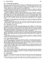
Part 3
Holographic Devices
11
Application of Holograms in WDM Components
for Optical Fiber Systems
Alfredo Martín Mínguez and Paloma R. Horche
ETSIT-Universidad Politécnica de Madrid
Spain
1. Introduction
Coarse Wavelength Division Multiplexing (CWDM) technologies are being widely deployed
internationally in metropolitan and access networks due to the increased demand for
delivering more bandwidth to the subscriber, created by the need of enhanced services,
(Koonen, 2006). For metro, and mainly for access networks applications, an increment in
capacity may be achieved with a cost-effective multiplexing technology without the need for
the high channel counts and closely spaced wavelengths typically used in long haul
networks. A channel space of 20 nm, as proposed in the G. 694.2 ITU Rec., can be used
relaxing the processing tolerances and potentially lowering the cost of components. CWDM
technology reaches those requirements and it has been proposed for these applications. It is
in this context that holographic optical devices have a potential use.
This chapter describes the theory, design, and experimental results of a generic multipurpose
device that can operate as a tunable wavelength filter, wavelength multiplexer and
wavelength router. This device could be especially useful in optical network applications
based on both Coarse and Dense Wavelength Division Multiplexing technology
(CWDM/DWDM). The enabling component is a Ferro-electric Liquid Crystal (FLC) Spatial
Light Modulator (SLM) in which dynamic holograms are implemented in real time. As a
consequence, the device will be able to carry out different functions according to the hologram
recorded on the SLM. The great advantage of this device is polarization insensitivity in the
region of operation, allowing low cross-talk and simple handling. As hologram management is
the basis for this device, some topics in the Computer Generated Hologram (CGH) design
process are commented on and general guidelines are also considered.
Laboratory experiments have demonstrated the capability of a phase FLC-SLM, with the
great advantage of polarization insensitivity operation, to diffract the incident light
according its wavelength and hologram patterns, for the use in the former applications.
Two typical applications of this technology are described: the first one is a design of an
equalized holographic Reconfigurable Optical Add-Drop Multiplexer ( ROADM), where
this device can address several wavelengths at the input to different output fibers, according
to the holograms stored in a SLM (Spatial Light Modulator), all the outputs being equalized
in power; the second one is dealing with the design of an holographic router with loss
compensation and wavelength conversion whose main application is in Metro networks in
the interconnection nodes. This device uses a SOA (Semiconductor Optical Amplifier), in the
non linear region, to do the wavelength conversion and, in addition, to supply the gain in
order to compensate for the intrinsic losses of the holographic device.
Holograms – Recording Materials and Applications
258
2. Operating principle
The working principle of a holographic device design is based on the wavelength dispersion
produced in a diffraction grating element (Agrawal, 2002). When a polychromatic light
reaches a diffraction grating, there is an angular dispersion (diffraction) according to the
incident light wavelength.
Equation (1) expresses the relationship between the diffraction angle and the wavelength of
the incident light λ:
sin
m
d
(1)
by considering the incident light perpendicular to the grating, Ф is the diffracted light angle,
m is the diffraction order and d the grating spatial period.
The light diffracted, in a far field approximation, follows the Fourier transform distribution
and the intensity for the different diffraction orders,
m, is proportional to sinc
2
(Фd/λ); the
separation between diffraction orders is given by
λR/d, where R is the distance between the
binary transmissive diffraction grating and the Fourier plane (Kashnow, 1973).
Most diffraction grating elements are not practically useful for changing the spatial period
or the wavelength. A way to allow these variations is, by using a Spatial Light Modulator
(SML), to implement on it a Computer Generated Hologram (CGH). The pixelated structure
of the SLM produces the effect of a two-dimensional diffraction grating when the device is
illuminated with a coherent light. In the SLM every ferro-electric liquid crystal (FLC) pixel
can be electro-optically configured to provide a phase modulation to the incident light.
Therefore, by managing the hologram on the SLM and its spatial period a programmable
diffraction grating is obtained.
In optical fiber communications, wavelengths around 0.8 – 1.6 µm are used. Thus, an SLM
pixel pitch close to these wavelength values is required. Unfortunately, current commercial
SLMs do not have enough resolution. Therefore, to solve this limitation, a fixed diffraction
grating with a low spatial period, together with the SLM giving a high resolution filter, is
used (Parker et al., 1998).
2-Phases 4-Phases
% darkness PHASE (rad) % darkness PHASE (rad)
black 100 0 100 π/4
grey1 - - 66 3π/4
grey2 - - 33 -3π/4
white 0 π 0 -π/4
Table 1. Relationship between phases and contrast
2.1 2 and 4-phases holograms
Different types of holograms can be used (Horche & Alarcón, 2004) in the SLM. In order to
optimize losses, phase holograms are preferred instead of amplitude holograms due to its
intrinsic 3 dB of loss and 4-phase holograms are used instead of 2-phase (binary) holograms
because of its greater efficiency (40.5%
81%), which is proportional to sinc
2
(π/M), where
M is the number of phases. Table 1 summarizes the relationships between phase and
contrast for 2 and 4 phase holograms.
Application of Holograms in WDM Components for Optical Fiber Systems
259
d = d
2-phases
d = d
4-phases
A
A
2A
m = 0
m = +1
m = +1
m = -1
m = 0
2-phases
4-phases
hologram
diffraction
η
2-phases
≈ 40%
η
4-phases
= 2η
≈ 80%
λ.R/2d
λ.R/d
Phase Holograms
white &
black bars
white, black
& grey bars
R
R
Fig. 1. two/four-phases bars holograms
Fig 1 shows a bars hologram for 2 and 4-phases and their diffraction target in a far field
approach. As we can see, the main difference in the holograms is the grey bars in the 4-
phases holograms; in this case there is a white bar, a black bar and two different grey bars
for addressing the 4-phases (π/4, 3π/4, -3π/4, -π/4); with regard to the diffraction target.
Another characteristic is the loss of the symmetry for the diffraction orders.
2-phases 85% eff
4-phases 85% eff
Target Result
Hologram
Target Result
Fig. 2. Examples of 2/4-phases holograms and diffraction targets
In Fig. 2 examples of calculated holograms are shown. The program calculates the inverse
Fourier transform (F.T.)
-1
of the diffraction target (result) by an annealing optimization
algorithm. In this case both holograms have a calculated efficiency of 85% and the grey bars
are clearly visible in the figure. In the following Section some guidelines about design of
holograms by computer are given.
Holograms – Recording Materials and Applications
260
2.2 Computer generated hologram design
Taking into account the former considerations and by implementing a hologram on the SLM
where its spatial period can be modified in real time, we obtain a programmable diffraction
grating.
The relationship between the hologram and its Fourier Transform function are:
Hologram F.T. Diffraction target
Diffraction target F.T
1
Hologram
In order to implement the CGH, holograms are calculated by using a program based on a
variation of the widely adopted simulated annealing optimization algorithm (Dames,
Dowling et al., 1991), (Broomfield, Neil et al., 1992) whose cost function to minimize the
calculation error is:
222
2
()
i
t
i
IA
C
A
(2)
where I
i
2
is the calculated spot intensity for the diffraction order i; A
i
2
is its defined intensity
and A
2
is the average intensity for the diffraction target spots; t is the number of process
calculations.
There are three steps in a CGH design process:
1.
Target definition: the target is the diffraction pattern that is to be obtained from the
SLM. Depending on the use: filter, switch or others, this target is usually an array or a
matrix of spots. This is the input for the program.
2.
Fourier transform calculation: the program calculates the inverse Fourier transform
(F.T.)
-1
of the target. The optimization algorithm compares the FT of the hologram with
the defined target improving the efficiency at each calculation time. Hologram pixels
are flipped between the amplitude values 0,
(or phase 0, π) to reduce an error
function, (2), specifying the difference between the desired target in the Fourier plane
and the reconstruction obtained from the current state of the hologram, improving the
efficiency at each calculation (Efficiency defined as: η = Σ m orders diffracted light /total
incident light).
3.
Finally, CGH implementation in an optical substrate, using a photographic film or
SLM.
The CGH designed for this work is a black & white bars pattern implemented onto a Spatial
Light Modulator, where there are only two possible states: “1” for white (total transparency
or π phase shift) and “0” for black (total darkness or 0 phase shift). Fig. 3 shows the original
diffraction target (a), an array of spots with different light intensities (non uniform, as in Fig.
3a), and three consecutive holograms (b, c, d), calculated by the program carrying out the
inverse FT according to the algorithm efficiency. A 45% efficiency is an initial calculation
value and close to 90% efficiency is practically the best result in the optimization process.
During the calculation of the hologram, the program can find out different holograms which
match the diffraction target. It is possible to change, dynamically, the initial conditions
(original diffraction target and efficiency, optimization process parameters), to change the
direction for the optimization process allowing the algorithm to escape from local minima
and reach the correct hologram.
Application of Holograms in WDM Components for Optical Fiber Systems
261
a) Diffraction target b) η= 45% eff hologram
c) η =7 0% eff hologram d) η=90% eff hologram
a) Diffraction target b) η= 45% eff hologram
c) η =7 0% eff hologram d) η=90% eff hologram
Fig. 3. Hologram calculation process according to the algorithm efficiency η. a) diffraction
target; b), c) and d) are calculated holograms with η = 45%, 70% and 90%, respectively
Fig. 4. a) “Zoom” of the original diffraction target, b) original shifted diffraction pattern
along the y axis, c) calculated diffraction target and d) corresponding hologram when the
original pattern is shifted
Computer calculations are very sensitive to the geometrical distribution of the original
diffraction target. A very slight misalignment on it (centre: x = 0, y = 0) can produce a
hologram completely different from the correct one. This effect is shown in Fig. 4 when the
original array of spots (Fig. 4a) is shifted by 30% of spot separation δ (Fig. 4b), along the
vertical axis y; the calculated target (Fig. 4c) is an array of spots “duplicated” and “shifted”
instead of a singular one.
To avoid small misalignments, along the x axis, of the output fibers array positions , with
impact on the efficiency, we can optimize the hologram pattern, introducing an offset in the
bar positions to correct them (Crossland et al., 2000) An offset of 5% of the hologram period
would impact the efficiency up to a 40%.
Holograms – Recording Materials and Applications
262
For the operation of holographic devices after the generation of holograms, it is necessary to
configure with them the SLM. To perform the switching operation a closed control between
the holographic component (SLM) and the computer is needed to assign the correspondent
hologram from a local database. This procedure is represented in Fig. 5, where a switching
control acts over the PC-SLMs interface.
H
1
, H
2
, H
i
, H
n
PC-SLMs Interface
SLMs
1
M
Switching control
Holograms (H
i
) stored in
the PC
Holographic device
n
ij
(H
i
assigment to the SLM
j
)
according to n
ij
Fig. 5. Tunable holographic device: switching operation
3. Dynamic holographic device design
In order to design a holographic optical device a “4f” structure is chosen using a
transmissive SLM and fixed grating. Fig. 6 illustrates the device used in the present work.
The previously calculated CGH (black and white bars) is loaded onto the SLM via a PC-
based interface. The SLM-FLC and fixed grating are illuminated by light coming from a
singlemode optical fiber collimated by means of a lens. A second lens produces the
replicated array of spots explained above on the back focal plane of the lens.
In our experiments, we are interested only in the array of spots corresponding to the first
order of diffraction. Therefore, the output optical fibers array is placed in the back focal
plane of the lens at a certain angle in order to optimize the coupling. Because of the small
size of the singlemode fiber radius, it acts as a spatial light filter.
Output fibers F
1
, ,F
10
, must be located at the Fourier lens plane in order to receive the
maximum light intensity of the diffracted beams. The relationship between the system
diffraction angles (Parker et al., 1998) is in agreement with the expression:
arctan arcsin arcsin
x
f
dH
(3)
where x is the distance of the output optical fiber from the optical axis, f is the focal length of
the lens, d is the spatial period of the fixed grating and H is the hologram spatial period,
Application of Holograms in WDM Components for Optical Fiber Systems
263
which relationship with D, the size of the pixel, and N, the number of pixels in one
dimension of the SLM is given in (4):
0
2
ND N
Hn
n
(4)
where n is the integer number of black & white bar pairs and depends on the type of
hologram (pattern). For small angles, equation (3) can be simplified as follows:
1
1
x
n
f
ND d
(5)
input fiber
lens 1
lens 2
output
fibers
SLM fixed grating
f
fx
f
f
ND
input fiber
lens 1
lens 2
output
fibers
SLM fixed grating
f
fx
f
f
ND
Fig. 6. “4f ”dynamic holographic device with a transmissive SLM and fixed grating.
When the other holographic device parameters are fixed, λ only depends on n, as can be
shown from (5). According to fixed or variable values for n or/and x, different applications
for our device can be considered giving an idea of the device’s versatility (see Table 2).
In the following sections, we design a generic multipurpose device based on the
experimental scheme explained above that can operate as a tunable wavelength filter,
wavelength multiplexer and wavelength router, by simply modifying in real time the CGH
loaded on the SLM. The PC-based interface used to load the CGH on to the SLM also serves
to calculate the different patterns needed. The electronic interface allows an automatic
program to be developed for loading different patterns when they are needed.
n x Application
fix fix Holographic band-pass filter
variable fix Tunable holographic band-pass filter
fix variable Demultiplexer 1x M
variable variable λ router 1x M
Table 2. Different device applications
In all cases, the central wavelength channel, λ
0
, is obtained for n = N/4 in (5), and the
operating wavelength range Δλ
f
is given by:
Holograms – Recording Materials and Applications
264
0
2
f
N
nn
(6)
The -3dB passband width, BW, for each wavelength channel tuned, is limited by the output
fiber characteristics and the wavelengths coupled inside the core diameter φ
core
. Taking this
into account, and from (3), the following expression relates the bandwidth BW for every
wavelength channel tuned in the filter and the focal distance f of the lens according the
optical power coupled into the output optical fiber (Parker et al., 1998):
3/2
2
0
2
1-
core
d
f
BW d
(7)
In order to obtain minimum losses, the collimated light through the SLM has to illuminate
the maximum quantity of pixels. As its intensity distribution has a Gaussian profile, it is
sufficient that 1/e
2
beam bandwidth illuminates the SLM aperture. According to optical
Gaussian laws, the following condition is reached:
0
4
core
f
ND
(8)
For commercial FLC-SLMs, available pixel size D is > 5 µm and the number of pixels, N,
usually is from 250 to 1000. From expressions (5) and (7), it is possible to calculate the x
value and λ
max
and λ
min
for the operating range of tuning.
4. Tunable holographic filter application
In order to design a tunable holographic filter with a -3dB passband width, BW, of 1 nm (125
GHz), for each wavelength channel tuned, we take d = 3.5 µm for the spatial period of the
fixed grating. To use the same device for CWDM/DWDM, a SLM with a value of N = 720
and D = 7 µm for the spatial period, is chosen. The output singlemode fibers used in our
device have a core diameter, φ
core
, of 9 µm. Then, from (7), f must be greater than 23.9 mm.
As a practical value we assume f = 25 mm.
Table 3 summarizes the filter figures for CWDM systems applications where channels are
allocated between λ
min
= 1290 nm and λ
max
= 1590 nm, with central wavelength λ
0
= 1431 nm,
and for DWDM systems (λ
min
= 1530 nm and λ
max
= 1590 nm, λ
0
= 1551 nm).
CWDM DWDM
1270 -1590 Δλ (nm) 1510 -1590
1 BW (nm) 1
1431 λ
0
(nm) 1551
25.00 f (mm) 25.00
11.499 x (mm) 12.463
24.71 Ф (º) 26.51
1591 λ
max
(nm) 1591
1311 λ
mi
n
(nm) 1531
Table 3. Device parameters for CWDM(DWDM) systems
Application of Holograms in WDM Components for Optical Fiber Systems
265
The operation as a tunable CWDM/DWDM filter is obtained by changing the hologram
period, n. From the output fibers (F
1
to F
10
), a CWDM tunable filter uses F
4
and a DWDM
tunable filter uses F
8
(see Fig. 6).
In Table 4 tuning between 1311 < λ < 1591 nm (CWDM, output fiber F
4
) is obtained for 17 < n <
328 and between 1531 < λ < 1591 nm (DWDM, output fiber F
8
) is reached for 138 < n <201.
a)
n
328 276 227 180 136 94 55 17
λ (nm)
1311 1351 1391
1431
1471 1511 1551 1591
b)
n
201 180 159 138
λ (nm)
1531
1551
1571 1591
Table 4. a) Filter operation for CWDM (F4) and b) for DWDM (F8)
4.1 Wavelength response
For CWDM applications the holographic filter has a tuning range of Δλ
f
=1591 -1311 = 280
nm with a -3dB passband of 1 nm. In Fig. 7 the transmission response is shown, according to
(Parker et al., 1998). For wavelengths very close to the centre, the shape is Gaussian (λ < λ
0
+/- 1,5 nm); from these wavelengths the shape is like a Bessel function and the zero
convergence is slower ( > 20 dB for λ > λ
0
+/- 1,5 nm ; > 40 dB for λ > λ
0
+/- 5 nm).
Table 5 shows, in case of CWDM systems, the different values of n and corresponding
central wavelengths separated by 40 nm, from 1311 to 1591 nm. In this case, an adjacent
channel isolation > 50 dB is achieved and the complete filter tuning range is covered
according to the type of hologram.
0
1,2 2,5 3,7
5
-1,2-2,5-3,7-5
-10
-20
-30
-40
Filter Bandwidth, nm
Transmission Loss , dB
0
1,2 2,5 3,7
5
-1,2-2,5-3,7-5
-10
-20
-30
-40
Filter Bandwidth, nm
Transmission Loss , dB
Fig. 7. Holographic filter shape. For wavelengths close to the central value, λ < λ
0
+/-1.5 nm,
the shape is Gaussian and like a Bessel function for wavelengths λ > λ
0
+/-1.5 nm
n 180 136 94 55
λ
0
(nm)
1431 1471 1511 1551
BW (nm)
1 1 1 1
Δλ (-3 dB)
1430.5-1431.5 1470.5 -1471.5 1510.5-1511.5 1550.5-1551.5
Δλ (>-50 dB)
1421-1441 1461-1481 1501-1521 1541-1561
Table 5. Tunable pass band filter (CWDM)
Holograms – Recording Materials and Applications
266
This feature allows the possibility of a multiple pass band filter in the same optical fiber, but
with an increment of losses penalty according to the expression 10 log C (dB), where C is the
number of simultaneously tuned channels (Parker et al., 1998). In this case, C = 4 and
therefore the increment of losses in the device is: Δ losses = 10 log 4 = 6 dB.
4.2 Loss estimation
There are three different sources of loss in this holographic device:
a.
SLM losses
An FLC-SLM works as a dynamic full π-binary phase fixed grating hologram with a
diffraction efficiency η = 36.5% (4.38 dB) for the first diffractive order (m =1) and a FLC
switching angle of 45º.
Another cause of losses is the insertion of the hologram, for a phase SLM, as a result of the
light polarization plane and FLC switching angle different to 45º (theoretical optimal angle);
at least another 2 dB are lost, assuming a good alignment of the collimated input light and
the FLC pixels.
b.
Fixed grating losses
The diffraction efficiency for a fixed grating, binary π-phase, is η = 36.5% for the first
diffractive order (m=1). That means a loss of 4.38 dB.
c.
Fiber/lens coupling efficiency
A fiber/lens coupling efficiency of 50% is a good approximation; therefore another 3 dB of
losses have to be added (2 dB, with very good alignment).
Losses can be improved using multiple-phase or blazed gratings; in this case the efficiency
can reach η ≈ 80 - 90% and the losses decrease to 1.5 dB (Ahderom, Raisi et al., 2002).
The estimated total losses of the device are: SLM losses + fixed grating losses + fiber/lens
coupling losses = (4.38+2) + 4.38 + 3 =13.76 dB and with loss optimization: (1.5+2)+1.5+2= 7
dB can be obtained.
5. WDM (wavelength division multiplexing) application
We can use this device as a 1x M demultiplexer, where M is the number of output fibers. For
this, a fixed value of n is used and the output fibers are located in certain x positions. Output
fibers (9/125 µm) must be placed in agreement with the diffracted angles Ф, according to
input wavelengths and they have to be separated at least Δx = 125 µm.
From (5), we can calculate the Δx taking the value of center to center wavelength channel
separation, Δλ, into account:
11nn
xf x f
ND d ND d
(9)
In order to design a compatible device with the frequency grid provided in ITU-T
G.694.1/G.694.2 Rec. for CWDM/DWDM systems, a 1x4 demultiplexer (M = 4) for DWDM
1
with Δx = 161 µm and a 1x8 demultiplexer (M = 8) for CWDM with Δx = 321 µm, can be
implemented.
1
In this case, Δλ’s < 20 nm are not feasible due to the physical dimension of the device (i.e. Δλ = 2 nm
and Δx = 161 µm f ,focal distance of the lens, = 25 cm).
Application of Holograms in WDM Components for Optical Fiber Systems
267
Table 6 summarizes the fiber positions in order to demultiplex the wavelengths used in the
CWDM/DWDM systems. A CWDM system uses F
1
, F
2
, F
3
, F
4
, F
5
, F
6
, F
8
and F
10
and a
DWDM uses F
7
, F
8
, F
9
, and F
10
output fibers (see Fig. 6). It is necessary to emphasize that a
better performance as demultiplexer could be implemented if only this function is required.
For example, we could design a demultiplexer device with channel separation smaller than
50 GHz (Parker, Cohen et al., 1997). However, the novel idea is to design a compatible
CWDM/DWDM device able to carry out different functions.
Output fiber
λ (nm) CWDM λ (nm) DWDM x(µm)
F
1
1311 10 535
F
2
1351 10 856
F
3
1391 11 178
F
4
1431 11 499
F
5
1471 11 821
F
6
1511 12 142
F
7
1531 12 303
F
8
1551 1551 12 463
F
9
1571 12 624
F
10
1591 1591 12 785
Table 6. CWDM/DWDM demultiplexers (n = 180)
6. Wavelength routing application
Maintaining output fibers in the same place as shown in Table 6, if n value (type of
hologram) is properly varied, a certain wavelength coming from the input fiber can be
routed to any one of the output fibers. As an example, Table 7 highlights the n values for
routing λ
0
= 1431nm (CWDM) and λ
0
= 1551 (DWDM) towards an output fiber; these values
have been calculated from (10), considering the variation of n according to Δx:
1xx
nNDnND
fd f
(10)
For Δx = 161 µm, Δn was calculated by using (10) resulting in Δn = 21 and for Δx = 321
µm, Δn is 45. Therefore, the device is a 1x8 λ router in case of CWDM and a 1x4 λ router
for DWDM systems. It is necessary to highlight that the positions of the fibers are
compatible with all applications and that the crosstalk resulting from high-order
diffraction beams (m =
2, 3,.) are outside of the locations of the output array fibers (ΔФ
= 4º), (Horche, 2004).
Holograms – Recording Materials and Applications
268
Output fiber
CWDM n value
λ
0
= 1431 nm
DWDM n value
λ
0
= 1551 nm
F
1
44
F
2
89
F
3
135
F
4
180
F
5
225
F
6
270
F
7
159
F
8
315 180
F
9
201
F
10
360 222
Table 7. CWDM/DWDM routers
7. Basic experimental results
In this section two complementary experiments have been made. The first one is related to
diffraction patterns measurements for different bars holograms and the second one to a SLM
characterization for holographic filters, demultiplexers and routers use with reference to the
devices whose design and characteristics have been described in the previous sections. Due
to the unavailability of components in the laboratory with the characteristics previously
described, the experimental optical bench is somewhat different from the appropriate one,
but, the measurements obtained are in agreement with the calculations.
In order to carry out the measurements, the experimental lab bench showed in Fig. 8 was
used; it is in agreement with the structure of Fig. 6, but, in this case, we used a reflective
SLM instead of a transmissive one; therefore, it is necessary to include a polarizing beam
splitter in order to direct the reflected beam to the lens. Due to the “spatial invariability” of
the Fourier transform, it is not necessary to illuminate the entire SLM active surface to
reproduce the diffraction pattern; taking this into account we can select, by a diaphragm
aperture, the SLM zone where the incident light is focused. The characteristics of a
commercial binary phase SLM are shown in Fig. 8(c).
As optical sources, a green He-Ne laser and a tunable Argon laser with λ
g
= 528.7 nm (green)
and λ
b
= 462.6 nm (blue) have been used. These wavelengths have been selected because
they belong to the visible spectrum and the correct alignment of the system is easier, a
critical factor in the experiment. In this case, a detector-array (6.3 × 4.7 mm) of a CCD
camera is placed at the “focal plane”, as an image sensor, to analyze the results.
A single personal computer, PC, is used to generate the CGHs for the design process
described previously, and they are loaded onto the SLM by changing its pixels state; the
diffracted patterns were stored in the same PC, where they could be observed and
processed. To recalculate the new output fibers position, the distance for the diffraction
order (x) is derived from (5) without the fixed grating:
f
x
H
(11)
where H, defined in (4), is the hologram spatial period, but now, the maximum value for n
= N/2 = 128, the size of the pixel, D =15 μm and the number of pixels in one dimension of the
Application of Holograms in WDM Components for Optical Fiber Systems
269
SLM, N = 256, have been taken into account. Fig. 9 summarizes the new fiber positions (F
1
to
F
8
) with a separation of ∆x = 176.23 μm between them.
a)
3,84 x 3,84
mm
Active area
87 %Fill factor
15
µm
D
256N
3,84 x 3,84
mm
Active area
87 %Fill factor
15
µm
D
256N
b) c)
Fig. 8. (a) Optical bench diagram; (b) experimental optical bench and c) binary phase SLM
characteristics
He -
N
e Laser
Aperture
Spatial Filter
lens
Aperture
Attenuator
Aperture
lens
CCD
camera
PC
-
hologram generation
-
SLM control
- CCD camera image capture
SLM
control
Focal
p
lane
Image
p
lane
a)
He -
N
e Laser
Aperture
Spatial Filter
lens
Aperture
Attenuator
Polarizating beam splitter
SLM
Aperture
lens
CCD
camera
PC
-
hologram generation
-
SLM control
- CCD camera image capture
control
Focal
p
lane
Image
p
lane
a)
Holograms – Recording Materials and Applications
270
0
32
64
96
128
0 150 300 450 600 750 900 1050 1200 1350 1500
Blue
Green
Fiber Position, x (µm)
n
F
2
352.46
F
1
176.23
F
3
528.70
F
4
704.93
F
5
881.16
F
6
1057.40
F
7
1233.63
F
8
1409.86
Fig. 9. New output fiber positions for the experimental measurements with two different
λ’s: λ
g
= 5287 nm (green) and λ
b
= 4626 nm (blue)
7.1 SLM characterization for wavelength routers
When we implement different holograms, according to n values, in the SLM and an incident
light wavelength is illuminating the pixels, different diffracted angles are obtained; by
placing an array of fibers at the output, in the focal plane, a λ-router is implemented.
To test the capability of a commercial SLM as a part of a dynamic holographic router, the
holographic setup shown in Fig. 8 (a) was implemented; a photo of the experimental optical
bench is shown in Fig. 8(b). For this test the optical source was an He-Ne laser at λ = 528.7
nm (green wavelength) and the lens focal length, 8 cm.
In order to route the green wavelength to the F
4
output fiber, according to Fig. 9, it is
necessary to load a CGH-(A) with a spatial period H corresponding to n = 64 in the SLM and
for routing the same wavelength to the F
8
output fiber, a CGH-(B) with n = 128 was
calculated and implemented onto the SLM.
7.2 SLM characterization for filters and demultiplexers
Other measurements, to test the capability of a commercial SLM as a part of a dynamic
holographic device, have been done with the holographic setup shown in Fig. 8 (Alarcón,
2004). According to Fig. 9, if a CGH black & white bars type hologram with n = 128 is loaded
onto the programmable SLM, a blue wavelength channel will reach the F
7
output fiber and a
green wavelength channel will reach the F
8
output fiber.
The diffracted light spots distance, calculated from (9) without a fixed grating, is:
n
xf
ND
(12)
where: Δλ = 66.1 nm; f = 8 cm; n = 128; N = 256 and D = 15 μm.
In Fig.10 light spots captured by CCD camera, from the CGH with n = 128 (black and white
bars) are shown. In this case the tunable Argon laser with the blue and green colors has been
used. The experimental diffracted light spot distances were x
blue
= 1233.6 µm (F
7
) and x
green
=
1409.8 (F
8
) µm, separated by ∆x = 176.25 µm according to Fig. 9, in good agreement with
(12). Therefore, in this way, we can build an optical 1x2 demultiplexer.
Application of Holograms in WDM Components for Optical Fiber Systems
271
Fig. 10. Diffracted wavelengths with a phase FC-SLM. A tunable Argon laser with λg = 528.7
nm (green) and λb = 462,6 nm (blue) is used. An Δx = 176.25 µm (diffracted wavelengths
separation) is obtained
The central light spot is due to the zero diffraction order m = 0, with the maximum light
intensity diffracted (x = 0); it can be reduced with a SLM with better performance by
impacting on the total insertion losses reduction.
The temporal response of the system was also measured. The SLM optical switching time
was estimated to be roughly 250
s, as the sum of the electric storage and FLC material
response times (Alarcón, 2004). We also noticed a damped response when low-frequency
switching is carried out; this is probably due to relaxation of the FLC molecules.
8. Design of equalized holographic ROADMs for application in CWDM metro
networks
These type of ROADMs are designed for application in CWDM (Coarse Wavelength
Division Multiplexing) networks, where the distance between the different wavelengths
allow the use of DML (Direct Modulation Lasers) without cooling, reducing the cost and the
tolerances of the network components. Application in METRO networks and its
interconnection with some PON (Passive Optical Network), as a part of the access to the
subscriber, is reviewed.
Different technologies have been proposed for the implementation of ROADMs (Ma & Kuo,
2003), (Homa & Bala, 2008). Each of them has its own advantages and drawbacks. The main
characteristic of holographic ROADMs is the easy way of changing the tuning and power
level of the signal at the output fibers by the dynamic implementation of different
holograms on the SLM according to the requirements of the network management.
8.1 Holographic ROADM structure
The working principle of the dynamic holographic device is based on the wavelength
dispersion produced in a diffraction component (grating, spatial light modulator) as
explained in Section 3.
We use for this application a phase reflective spatial light modulator (SLM) and a fixed
transmissive diffraction grating to select the corresponding output wavelength from an set
of channels in the input, as shown in Fig 11. The active element of the SLM is a Ferroelectric
Liquid Crystal (FLC) with a low switching time (less than 50 μs) that allows a real time
Holograms – Recording Materials and Applications
272
operation. The role of the fixed diffraction grating is to provide more wavelength tuning
range and greater total diffraction angle.
Fig. 11. Reflective holographic router
One of the reasons because we have chosen this type of “2f-folded”implementation, , is the
reduced size of the device in comparison with the other possible structure, “linear-4f”,
where the length of the optical axis is four times the focal distance of the lens used. Its
working operation has been described in Section 3.
8.2 Holographic ROADM design
8.2.1 Dynamic wavelength tuning
At the input of the router there are different wavelengths λ
1
, λ
2
,…. λ
n
according to some ITU
Rec. For the design of this holographic router, these wavelengths are in agreement with the
G.694 Rec. for use in CWDM systems. The range of wavelengths is from 1271 nm to 1611 nm
with 20 nm as separation between channels; 4, 4+4, 8, 12 and 16 groups of channels are
specified distributed along the complete range.
In a holographic router the tuning of this wavelength range is achieved by changing the
spatial period of the hologram ND/n, where n is the number of pairs of bars (2-phases) or
number of four bars (4-phases), N is the number of pixels and D the size of the SLM pixels.
The expression which allows the selection of the output wavelength λ, according to the
physical parameters and structure of the device, is (Martin Minguez & Horche, 2007):
1
2
(/2).
x
f
n
ND M d
(13)
where x is the distance from the optical axis to the output fiber, f is the focal length of the
lens, d is the spatial period of the fixed diffraction grating and M is the number of phases.
Fig. 12 shows some tuned wavelengths according to different values of n, for a typical
holographic device.
Application of Holograms in WDM Components for Optical Fiber Systems
273
Fig. 12. Four different tuned wavelengths at the output of the holographic router
As we have commented in Section 4.1, for wavelengths close to the central value, the filter
response is very similar to the Gauss filter; for wavelengths far from the central value, the
filter response is similar to a 3
nd
order Bessel filter with less out band attenuation. Both of
them have a linear phase characteristic, which means a constant group delay. These
simulations are in agreement with experimental measurements shown in (Parker et al ,
1998).
8.2.2 Holographic device losses
The losses produced in this holographic router, as we have commented before, are due to
the following causes:
-
diffraction loss: the total light diffraction is composed of the transmissive diffraction in
the grating (twice) and the reflexive diffraction in the SLM. Using a 4-phases SLM and a
grating with 1
st
order intensity efficiency of about 80%, the total losses are 10 x log
(3x.0.8) ≈ 3 dB.
-
intrinsic SLM loss: it is due to the liquid crystal (LC) switching angle different from
optimal and the coverage of SLM aperture (1/e
2
of ND x ND). A typical value is 2 dB.
-
fibre/lens coupling: by considering 90% efficiency, 1 dB is added.
In total, with an optimized holographic device, a loss about 6 dB has to be taken into
account.
8.2.3 Channel power equalization
Power equalization at the all output channels is necessary to compensate the different
response of the network components and distances for the used channel wavelengths. To
reach it and to compensate for the holographic device losses, a gain component, such as a
Semiconductor Optical Amplifier (SOA), has to be employed. The total equalization takes
into account the gain-wavelength variation of this amplifier, ΔG
A
, whose typical response is
drawn in Fig. 13, (the maximum gain, G
A
is about 20~25 dB).
Holograms – Recording Materials and Applications
274
Fig. 13. Incremental gain (ΔG
A
) of a typical CWDM SOA
The target is to have at the output fibers a net loss of 0 dB (GT), according to the equation:
10lo
g
( ) 0
TA A HR
G G G number of channels L At
(14)
where ΔAt is the total attenuation range for channels to be equalized at the input of the
device; L
HR
is the intrinsic holographic router losses (≈ 6 dB) and the term ΔL
HR
=10 x log
(number of channels) has taken into account the additional loss due to the mixed holograms
utilized for equalizing all the input channels. This point will be explained in detail in the
following paragraphs. Fig. 14 shows the structure of an Equalized Holographic ROADM
(EH-ROADM) for 4 input channels with full routing of them to the 4 output fibers. A way to
obtain at the output fibers tuned wavelengths with different relative attenuation between
them is to control the losses due to the SLM aperture, as pointed out in Fig. 15.
SOA
H
Req
G
A
, ΔG
A
L
HR
, Δ L
HR
λ
1
λ
4
λ
3
λ
2
L
T
Holograms
in
out
λ
1
λ
2
λ
3
λ
4
Fig. 14. Equalized Holographic ROADM 1x4
The minimum losses due to the SLM aperture are obtained when the incident light, with a
Gaussian distribution, fills the complete surface ND x ND of the SLM. Therefore, the losses
are proportional to the quantity of SLM aperture illuminated by the collimated light coming
from the lens, as in Fig. 15. A practical way to reach the former condition is by changing the
size of the hologram according to the number of active pixels.
Application of Holograms in WDM Components for Optical Fiber Systems
275
gaussian light
1/e
2
f
f
ND
ND
φ
core
λ
0
collimating lens
SLM
o
core
NDf
4
Fig. 15. Losses in the incident light due to different ND x ND hologram apertures
8.2.4 Mixed hologram operation
The EH-ROADM is able to select at the output fibers any combination of wavelengths at the
input fiber, from all input wavelengths in just one output fiber to each input wavelength at
the corresponding output fiber, including all intermediate cases. This operation mode is
done by the selection in the SLM of a mixed hologram composed of all individual
holograms corresponding to each input wavelength.
Fig. 16 shows an example for three input wavelengths and its holograms, formed, in this
case, by black and white bars (2-phases). For every input wavelength (channel) a hologram
is assigned, where n
i
(spatial period) produces the pass-band filter for the channel and N
i
Mixed holograms espectra
-40
-35
-30
-25
-20
-15
-10
-5
0
1501 1511 1521 1531 1541 1551 1561
λ
channel
(nm)
At
channel
(d
B)
+
+
SLM equalization
n (hologram spatial period): λ
channel
N (hologram surface): At
channel
n
1
,N
1
=
λ
1
,At
1
λ
2
,At
2
λ
3
,At
3
Mixed hologram
n
2
N
2
n
3
,N
3
Fig. 16. Mixed holograms operation
Holograms – Recording Materials and Applications
276
takes into account the number of active pixels to reach the correct attenuation, At
channel
, to
equalize the output signals. This mixed hologram produces the additional loss in the
holographic router, 10 x log (number of channels). A more fitted equalization can be obtained
by monitoring the outputs with a feed-back loop to adjust the size of the holograms
according to the wanted output signal level.
8.2.5 Design calculations
Having chosen the SLM, the focal length of the lens, f, to illuminate with collimated light the
complete active surface ND x ND of the SLM (see Fig.15), is related to the number of pixels
N and their size D according to expression (8):
0
4
core
ND
f
(15)
where Φ
core
is the input fiber core diameter and λ
0
the central wavelength in the operation
region. The 3 dB pass-band filter bandwidth of the device, BW, is (Parker et al., 1998)
3/2
2
0
2
(/2).
1
(/2.)
core
Md
BW
fMd
(16)
if the condition 8D >> d is reached, where d is the fixed grating spatial period. For our
calculations, we have a reflective 4-phases SLM with N = 1024 and D = 8 μm (ND = 8.192
mm). Then, the focal distance for the lens is 37.655 mm and the BW ≥ 1.52 nm (190 GHz), d
being = 6.5 μm, the spatial period of a 4-phases transmissive diffraction grating and Φ
core
=
9 μm the core diameter of a singlemode fiber. By changing d we can adjust the BW of the
holographic filter.
In the expression (13) the selected wavelength of operation is calculated. The value of n is
varied from n = 0 (for maximum wavelength) and n = N/4 (for minimum wavelength); the
central wavelength λ
0
is obtained when n = N/8. For the design of a 1x4 router working in
the upper band of the CWDM grid, 1471-1611 nm, we take λ
0
= 1541 nm. In this case λ
min
=
1407 nm and λ
max
= 1693 nm; these values cover the entire CWDM upper band. The distance
from the optical axis to the output fiber, (see Fig. 11), where the 1
st
order of the total
diffraction is produced, is x = 9.808 mm and the total diffraction angle φ ≈ 14.6º.
From ITU G.694 Rec., all CWDM channels are spread Δλ = 20 nm to allow Direct
Modulated Lasers (DML) wavelength variation with temperature and filter tolerance;
therefore, an ΔΛ = (8-1).Δλ = 1611-1471 = 140 nm range assumes ΔX = 1260 μm, according
to the relation:
2
.
(/2).
n
xf
ND M d
(17)
This is the maximum interval, at the output plane, where all the output fibers have to be
placed. That mean, a separation between fibers of Δx = ΔX /(8-1) = 1260 / 7 = 180 μm. Single
mode fibers have a cladding diameter of 125 +/- 1 μm, so, we can reduce this separation to
aprox. 130 μm, if it is needed.
Application of Holograms in WDM Components for Optical Fiber Systems
277
n
i
j
(holograms)
λ
3
= 1511 nm λ
4
= 1531 nm λ
5
= 1551 nm λ
6
= 1571 nm x
j
(μm)
Fibre 3
113 95 78 61
9538
Fibre 4
139 121 103 85
9718
Fibre 5
165 146 128 110
9898
Fibre 6
191 172 153 135
10078
N
i
(pixels) 256÷1024 256÷1024 256÷1024 256÷1024
Table 8. Holograms and active pixels for an EH_ROADM 1x4
In an equalized holographic router, the directing of the input wavelengths to the output
fibers is done by the choice of three parameters: n
ij
for wavelength tuning, N
i
for power
equalization and Δx
j
for placing the output optical fibers. Subscript i is related to the number
of input wavelengths and subscript j related with the number of output fibers. Haqving
fixed the separation between fibers, in our case Δx = 180 μm, we obtain the corresponding
value of n
ij
from (13), according to the input wavelength(s) and output fiber(s) considered.
As we are managing different sets of n
ij
values, all of them have to be different in order to
avoid cross-talk between wavelengths on different output fibers.
Table 8 shows the holograms (n
ij
) and number of active pixels (N
i
) for a 4-channels grid
according to the ITU G.695 Rec. For instance, in Fig. 11, a mixed hologram 113+95+78+61
addresses the 4 input wavelengths (λ
3
+ λ
4
+ λ
5
+ λ
6
) to the output fibre 3; a mixed hologram
113+121+128+135 addresses λ
3
to fibre 3, λ
4
to fibre 4, λ
5
to fibre 5 and λ
6
to fibre 6. In each
case, every λ
i
has the corresponding N
i
range to assure the power equalization at the output.
Table 9 is a summary of the losses in the device (SOA+EH-ROADM) according to the
different input channels, whose variation in wavelength is in agreement with Fig. 15. In this
case, there is a net gain of 10 dB to compensate for the power variation due to different
paths of the input channels along the network. The N
i
range, 256÷1024, in Table 8 is to
compensate a total of 12 dB of attenuation; with a step of ΔN
i
= 16 the ripple at the output is
< 0.5 dB.
Intrinsic router loss (dB)
6
6
24
22
L
HR
Additional mixed hologram loss (dB)
ΔL
HR
[10 x log (4)]
Max. gain of SOA, G
A
(dB)
@ 1531 nm
Min. gain of SOA, G
A
(dB)
@ 1571 nm
λ (nm) ΔG
A
(dB) Total loss (dB)
1511
1.5 13.5
1531
2 14
1551
1 13
1571
0 12
Total min. net gain, G
T
(dB) 10
Table 9. SOA gain, EH_ROADM losses and total net gain
Holograms – Recording Materials and Applications
278
8.2.6 CWDM METRO networks application
The use of tunable holographic devices in Access and Metro networks, like demultiplexers
or routers has been studied in different papers (Koonen, 2006), (Martin Minguez & Horche,
2010). In Fig. 17 an application for the equalized holographic ROADM is represented.
CWDM METRO
network
FTTO
FTTH
LONG HAUL
network
OXC: Optical Cross-Connect
OLT: Optical Line Termination
PON: Passive Optical Network
FTTH: Fiber to the Home
FTTO: Fiber to the Office
Primary path
Spare path
OLT
Node
Node
Node
OLT
}
Access Networks
DWDM METRO
network
*
*
*
* : location for tunable holographic devices use
PON 1
PON 2
PON 3
PON 4
λ
1
λ
2
λ
3
λ
4
λ
1
λ
2
λ
3
λ
4
*
oxc
ROADM
ROADM: Reconfigurable Optical Add-Dropp Multiplexer
Fig. 17. Application of an EH_ROADM in a CWDM METRO network
A double ring CWDM METRO topology is used to connect this primary access network,
through an Optical Line Termination (OLT), with some Fiber to the Office (FTTO) or Fiber to
the Home (FTTH) networks with Passive Optical Network (PON) structure; on the other side,
a connection to a DWDM METRO network, by an OXC (Optical Cross Connect) with λ
conversion, is provided. The target is to address the wavelengths of the double ring network,
λ
1
, λ
2
, λ
3
and λ
4
to four different PONs with the possibility of wavelength reallocation.
9. Design of an holographic router with λ conversion and losses
compensation
Fig. 18 shows a device composed of a Semiconductor Optical Amplifier (SOA) and a
holographic wavelength router. The SOA performs the wavelength conversion by a non
linear operation using the Cross Gain Modulation (XGM) method. An incident wavelength,
λi, modulated by a digital signal is combined with the wavelength λ
CWj
generated by a
tunable laser (CW) into the SOA. At the amplifier output, according to different CWj
wavelengths, λ
CWj
signals are obtained modulated with the digital signal from the incident λi
wavelength. These λ
CWj
signals are also amplified and inverted.
The holographic wavelength router, depending on the input signal, λ
CWj,
, and the generated
hologram (nij) stored in the SLM, addresses this signal to the assigned output. As has been
stated, this technology has the drawback of high insertion losses (less than 10 dB, using an
optimized device). In order to solve this problem, by combining a SOA with the holographic
router, this insertion loss is compensated with the amplifier gain in the saturation zone of
operation. A parameter to control in the SOA operation, is related to the amplified
spontaneous emission (ASE) because of the impact on the signal distortion.
Application of Holograms in WDM Components for Optical Fiber Systems
279
Fig. 19 shows the simulation of this device, composed of three different blocks: a CW
tunable laser, a wavelength conversion semiconductor optical amplifier and a wavelength
holographic router. In Fig. 20, the response of the Wavelength Conversion and Routing
Holographic Device (WCR-HD) is represented for a 2.5 Gb/s input signal, λi = 1540 nm,
which is converted to an output signal, λo = 1520 nm, where the losses of the holographic
router are compensated by the gain of the SOA.
SOA
HOLOGRAPHIC
λ ROUTER
λ
CWj
λ
i
(modulated)
λ
CW1
λ
CW2
λ
CW3
λ
CW4
λ
CW1
λ
CW2
λ
CW3
λ
CW4
All optical switching
(λ conversion + λ routing)
losses: 10 dBgain: 10 dB
Insertion losses: 0 dB
Tunable laser
Control
Control
Fig. 18. Device composed of an optical λ converter and a holographic λ router
Fig. 19. Wavelength Conversion and Routing Holographic Device (WCR-HD) simulation