ZTE MG3006 Module Technical Specifications potx
Bạn đang xem bản rút gọn của tài liệu. Xem và tải ngay bản đầy đủ của tài liệu tại đây (905.88 KB, 27 trang )
GSMMG3006 moduleproduct
ZTEMG3006ModuleTechnicalSpecifications
VERSION:V1.3
ZTECORPORATION
GSMMG3006 module products
1
Copyrig htStatement
Copyright
©
2007byZTECorporation
Allrightsreserved.
Nopartofthispublicationmaybeexcerpted,reproduced,translatedorutilizedinanyformorbyany
means, electronic or mechanical, including photocopying and microfilm, without the prior written
permissionofZTECorporation.
istheregisteredtrademarkofZTECorporation.Allothertrademarksappearedinthis
manualareow nedbytherelevantcompanies.
ZTECorporationreservestherighttomakemodificationsonprinterrorsorupdatespecificationsin
thismanualwithoutpriornotice.
ZTECorporationkeepstherighttomakethefinalexplanationtothismanual.
GSMMG3006 module products
2
Withstrongtechnicalforce,ZTECorporationcanprovideCDMA/GPRSmodulecustomerswiththe
followingallaroundtechnicalsupport:
1.Prov idecompletetechnicaldocumentation;
2.Prov idethedevelopmentboardusedforR&D,test,production,aftersales,etc.;
3.Prov ideevaluationsandtechnicaldiagnosisforprinciplediagram,PCB,testscenarios;
4.Prov idetestenvironment;
ZTECorporationprovidescustomerswithonsitesupports,andalsoyoucouldgetsupportsthrough
telephone,website,instantcommunication,Email,etc.
The module website provides the relevant industry information and
module technical documentation. The authorized module customers could download the latest
technicaldocumentationforourwebsite.Ifyouhavemorerequirements,youcouldsendanEmailto
Youcanalsocallusat075586360280formoresupports.
GSMMG3006 module products
3
Foreword
Summary
The corresponding productto this documentis MG3006 modules. It introduces the appearance,
hardware framework, functions, technical specifications and relevant test standard of MG3006
module,whichisusedforsupportingdesignreferencetohardwareengineersandproductdesigners.
Objectreaders
Thisdocum entismostlysuitableforengineersasbelow:
l Systemdesigners
l Productengineers
l Hardwareengineers
l Softwareengineers
l Testengineers
Brief
Thisdocum entcontains7chapters,asfollowing :
chapter contents
1Summary Background,conceptsandapplicationsofMG3006
2Abbreviation Abbreviationsappearedinthisdocument
3appearanceandframework AppearancefigureofMG3006module
4functionsandinterfaces BasicfunctionsandinterfacesofMG3006module
5Technicalspecifications Introduceparticulartechnicalspecificationsof MG3006module
6reliabilityteststandard Introducethereliabilityteststandardof MG3006module.
7EMC/EMIstandard IntroduceEMC/EMIstandardofMG3006module
Modifiedrecords
Modified records accumulate update notes every time. The latest document version includes all
updatecontentspreviously.
DocumentversionV1.3(20071031)
AddTCP/IPprotocol
DocumentversionV1.2(20070817)
Releasedformallyforthe3rdtime,theupdatecontentsinclude:
changeME3006forMG3006.
ModifyVoiceencodingin5.1
DocumentversionV1.1(20070709)
Releasedformallyforthe2sttime,theupdatecontents include:
AddthismanualisalsoapplicableforME3006module.
GSMMG3006 module products
4
Modify6.Reliabilityteststandard
DocumentversionV1.0(20070531)
Releasedformallyforthe1sttime
GSMMG3006 module products
5
Tableofcontents
1SUMMARY 8
2ABBREVIATION 8
3APPEARANCEANDFRAMEWORK 9
4FUNCTIONSANDINTERFACES 10
5 TECHNICALSPECIFICATIONS 10
5.1 COMMUNICATIONPROTOCOLSANDTECHNICALSPECIFIC ATIONS 10
5.2 RF EMISSION 12
5.2.1Frequencyandphasebias 12
5.2.2Frequencyandphasebiasundermultipathinterference 12
5.2.3 Txpeakvaluepowerandpulseenveloptiming 12
5.2.4TXoutputspectrum 15
5.3 RF RECEIVING 17
5.3.1Referencesensitivity 17
5.3.2 Availablein putlevel 19
5.3.3Cochannelsuppression 19
5.3.4 Adjacentchannelsuppression 20
5.3.5Intermodulationsuppression 21
5.3.6Blockingandspuriousrespond 21
5.4 RECOMMENDATIONOFANTENNASPECS 23
5.5 POWERSUPPLY 23
5.5.1Inputvoltage 23
5.6 WORKINGCONDITIONS 23
6RELIABILITYTESTSTANDARD 24
6.1 LOWTEMPERATURERUNNINGEXPERIMENT 24
6.2 LOWTEMPERATURESTORAGEEXPE RIMENT 24
6.3 HIGHTEMPERATURERUNNINGEXPERIMENT 24
6.4 HIGHTEMPERATURESTORAGEE XPERIMENT 24
6.5 HIGH TEMPERATURE, HIGHHUMIDITYEXPERIMENT 24
6.6 HIGHLOWTEMPERATURESTRIKINGE XPERIMENT 24
7EMC/EMITESTSTANDARD 25
7.1 STATICDISCHARGE(ESD)INTERFERENCEIMMUNIT YEXPERIMENT 25
7.2 RF ELECTROMAGNETICEMISSIONINTERFERENCEIMMUNITY EXPERIMENT .25
7.3 ELECTRICALFASTTRANSIENT/BURSTIMMUNITYEXPERIMENT 25
7.4 LIGHTNINGANDSURGESTRIKEI MMUNITYEXPERIMENT 26
7.5 RF ELECTROMAGNETICFIELDCONDUCTION INTERFERENCEIMMUNITY EXPERIMENT 26
7.6 RADIATEDDISTURBANCEEXPERIMENT . 26
7.7 CONDUCTEDDISTURBANCEEXPERIMENT 26
GSMMG3006 module products
6
TABLEOFFIGURES
Figure31appear anceofMG3006module 10
Figure51Power/timeenvelopframeworkundernormaltestcondition 14
Figure52power/timeenvel opframeworkunderultratestcondition 15
GSMMG3006 module products
7
TABLES
Table51communicationprotocolsandtechnicalspecifications 10
Table52frequencyband 11
Table53intervalassignment 11
Table54encodi ngmodes 11
Table55datarate 11
Table56frequencybias 12
Table57err orratetestedineachchannelofGSM850andGSM900 18
Table58err orratetestedineachchannelofDCS1800andPCS1900 18
Table59err orratetestedineachchannelofGSM850andGSM900 18
Table510err orratetestedineachchannelofCS1800andPCS1900 19
Table511errorratelimitandminimumquantityofsamplesineachfullspeedchannel 19
Table512errorratelimitandminimumquantityofsamplesin eachhalfspeedchannelofGSM850and GSM
900 20
Table513errorratelimitandminimumquantityofsamplesineachhalfspeedchannelofDCS1800andPCS
1900 20
Table514theuselesssignallevelofGSM900andDCS1800 21
Table515TheuselesssignallevelofPCS1900 22
Table516TheuselesssignallevelofGSM850 22
Table517Errorratelimitandminimumquantityofsamplesineachchannel 22
Table518recommendedantennaspecs 23
Table519inputvoltage 23
Table71staticexperimentlevel 25
Table72emissionantiinterferenceexperimentlevel 25
Table73Electricalfastchangedpulsegroupantiinterferenceexperimentlevel 25
Table74Lightningandsurgestrikeantiinterferenceexperiment 26
Table75conductionantiinterferenceexperimentlevel 26
GSMMG3006 module products
8
1Summary
ZTEMG3006modulesisatypeofGSM/GPRSwirelessmodulesupportsQuadBand,withabundant
voice, SMS,dataservicefunctions and soon. The modules can beapplied indatatransmission,
wirelessPOS,security,lotterymachine,autometering,wirelessfax,smallswitch,tobaccomachine,
information machine, wireless AD, wireless media, medical ward, rem ote monitoring, railway
terminals,intelligentelectronicproductsandvehicletrackingsystem setc.
This document take MG3006 module as an example, introduces the appearance, hardware
framework,functions,technicalspecificationsandrelevantteststandardsformoduleindetail.
2Abbreviation
Abbr. Fullname
ADC
AnalogDigitalConverter
AFC AutomaticFrequencyControl
AGC AutomaticGainControl
ARFCN AbsoluteRadioFrequencyChannelNumber
ARP AntennaReferencePoint
ASIC ApplicationSpecificIntegratedCircuit
BER BitErrorRate
BTS BaseTransceiverStation
CDMA CodeDivisionMultipleAccess
CDG CDMADevelopmentGroup
CS CodingScheme
CSD CircuitSwitchedData
CPU CentralProcessingUnit
DAI DigitalAudioint erface
DAC DigitaltoAnalogConverter
DCE DataCommunicationEquipment
DSP DigitalSignalProcessor
DTE DataTerminalEquipment
DTMF DualToneMultiFrequency
DTR DataTerminalReady
EFR EnhancedFullRate
EGSM EnhancedGSM
EMC ElectromagneticCompatibility
EMI ElectroMagneticInterference
ESD ElectronicStaticDischarge
ETS EuropeanTelecommunicationStandard
FDMA FrequencyDivisionMultipleAccess
GSMMG3006 module products
9
FR FullRate
GPRS GeneralPacketRadioService
GSM GlobalStandardforMobileCommunications
HR HalfRate
IC IntegratedCircuit
IMEI InternationalMobileEquipmentIdentity
ISO InternationalStandar dsOrganization
ITU InternationalTelecommunicationsUnion
LCD LiquidCrystalDisplay
LED LightEmittingDiode
MCU MachineControlUnit
MMI ManMachineInterface
MS MobileStation
PCB PrintedCircuitBoard
PCL PowerControlLevel
PCS PersonalCommunicationSystem
PDU ProtocolDataUnit
PLL PhaseLockedLoop
PPP Pointtopointprotocol
RAM RandomAccessMemory
RF RadioFrequency
ROM ReadonlyMemory
RMS RootMeanSquare
RTC RealTimeClock
SIM SubscriberIdentificationModule
SMS ShortMessageService
SRAM StaticRandomAccessMemory
TA Terminaladapter
TDMA TimeDivisionMultipleAccess
TE TerminalEquipmentalsoreferreditasDTE
UART Universalasynchronousreceivertransmitter
UIM UserIdentifierManagement
USB UniversalSerialBus
VSWR VoltageStandingWaveRatio
ZTE ZTECorpora tion
3Appearanceandframework
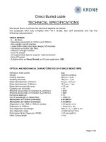
AppearanceofMG3006isasfollowingfigure31:
GSMMG3006 module products
10
Figure31appearanceofMG3006module
l Dimension(lengthxwidthxheight):44.0mmx28.0mmx7.6mm
l Weight:8g
4Functionsandinterfaces
Thebasicfunctionsof moduleareasbelow:
l SupportQuadBand:GSM850/EGSM900/DCS1800/PCS1900
l Supportpacketdataservice
l Supportcircuitswitcheddataservice
l SupportSMSservice
l Supportstandard AT commandsandextendedAT commands
l SupportstandardUART interf ace
l Supportdualpathaudiointerface
l Supplementaryservicefunctions:incomingcalldisplay,callforward,callmaintenance,call
standby,triplecallserviceandsoon.
l SupportTCP/IPprotocol
5Technicalspecifications
5.1Communicationprotocolsandtechnicalspecifications
ThecommunicationprotocolsandtechnicalspecificationsofMG3006modulesisasfollowingtable
51:
Table51communicationprotocolsandtechnicalspecifications
Accessmode GSM
Techspec GSMphase2/2+
GSMMG3006 module products
11
Rx/Tx
frequency
interval
45MHzforGSM850
45MHzforEGSM900
95MHzforDCS1800
80MHzforPCS1900
Voiceencoding – Halfrate(HR)
– Fullrate(FR)
– EnhancedFullrate(EFR)
– AdaptiveMultiRate(AMR)
l MG3006 frequency band : GSM 850/EGSM 900/DCS 1800/PCS 1900 MHz. There
frequency bands are shown in table 52. Data transmission rate depends on interval
assignmentandchannelencodingof GPRS.
Table52frequencyband
name Txfrequencyband(MHz) Rxfrequencyband(MHz)
GSM850 824~849MHz 869~894MHz
EGSM900 880~915MHz 925~960MHz
DCS1800 1710~1785MHz 1805~1880MHz
PCS1900 1850~1910MHz 1930~1990MHz
MG3006modulesupportsCLASS10,theintervalassignmentisasfollowingtableTable53:
Table53interv alassignment
down up Maximumsupportedintervalatthesame
time
4 2 5
GPRSencodingmodessupportedbyMG3006moduleareasfollowingtable54:
Table54encodingmodes
Encodingmodes Datarate(kbps)
CS1 9.05
CS2 13.4
CS3 15.6
CS4 21.4
ThemaximumtheoreticdataratesupportedbyMG3006moduleisasfollowingtable55:
Table55datarate
Encodingmode Download(kbps) Upload(kbps)
CS1 36.2 18.1
CS2 53.6 26.8
CS3 62.4 31.2
CS4 85.6 42.8
MG3006modulesupportsCl assB,butwhenGPRSandGSMservice existatthesametime,
GPRSbreaksoff,ontheotherhand,voiceandSMSserviceofGSMisprior.AfterthatGPRS
GSMMG3006 module products
12
servicecanresumeautomatically.
5.2RFemission
5.2.1Frequencyandphasebias
Thefrequencyandphasebiasoftransmittermeansthedifferencebetweentheactualfrequency
andphasevaluesandthetheoreticones.
l ThefrequencybiasofeachGSMfrequencybandshouldbelessthan0.1p pm
l RMSoneachchannelandpowerlevelshouldnotover5°.
l Peakvaluephasebiasoneachchannelandpowerlevelshouldnotover20°.
5.2.2Frequencyandphasebiasundermultipathinterf erence
It’sthecarrierfrequencybiasofMSunderDopplerfrequencyshift,multiplepathRxandinterference.
ThefrequencybiasineachfrequencybandpermittedbyGSMstandardisasfollowingtable56:
Table56frequencybias
GSM850andGSM900 DCS1800 PCS1900
Spread
condition
Allowable
frequencybias
Spread
condition
Allowable
frequencybias
Spread
condition
Allowable
frequencybias
RA250 ±300Hz RA130 ±400Hz RA130 ±420Hz
HT100 ±180Hz HT100 ±350Hz HT100 ±370Hz
TU50 ±160Hz TU50 ±260Hz TU50 ±280Hz
TU3 ±230Hz TU1.5 ±320Hz TU1.5 ±330Hz
5.2.3Txpeakvaluepo werandp ulseenveloptiming
Carrier peak value power of transmitter is the average value on a b urst pulse’s useful
informationbittime.
OutburstpulsetimingistheintervalbetweenRxandTxofMS.
Undernormalandultratestconditions,everycarrierpeakvaluepoweroneachpowerlevelofGSM
frequencybandshouldbeinthecontentsoffollowingtable:
l GSM850andGSM900:
GSMMG3006 module products
13
l DCS1800:
GSMMG3006 module products
14
l PCS1900:
Under the same frequency and test condition, the difference between two TX carrier peak value
powerofcloserpowercontrollevelshouldbenolessthan0.5dBandnomorethan3.5dB.ForPCS
1900,whenpowerlev elis 3,thedifferencebetweentwoTXcarrierpeakvaluepower,whose power
controllevelis30and31respectivelycontrollevelis30or31,shouldbenolessthan0dBandno
morethan2dB
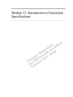
Undernormalandultratestcondition,power/timeenveloponeachpow ercontrollevelshouldbein
thepower/timeenveloprangeshowninfollowingfigure.
Power/timeenvelopf rameworkundernormaltestconditionisasfollowingfigure51:
Figure51Power/timeenvelopframeworkundernormaltestcondition
l ForGSM850andGSM900
1. 4dBcpowercontrollevel16
2. 2dBcpowercontrollevel17
3. 1dBcpowercontrollevel18,1931
l ForDCS1800andPCS1900
1. 4dBcpowercontrollevel11
2. 2dBcpowercontrollevel12
GSMMG3006 module products
15
3. 1dBcpowercontrollevel13,14and1528
l ForGSM850andGSM900
1. selectlargervaluebetween30dBcand 17dBm
l ForDCS1800andPCS1900
1. selectlargervaluebetween30dBcand 20dBm
2. minimumlimitvalue
l ForGSM850andGSM900
1. selectlargervaluebetween59dBcand 54dBm中
2. forDCS1800andPCS1900:selectlargervaluebetween48dBcand48dBm
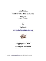
3. power/timeenvelopframeworkunderultratestconditionisasfollowingfigure52:
Figure52power/timeenvelopframeworkunderultratestcondition
l forGSM850andGSM900
1. 4dBcpowercontrollevel16
2. 2dBcpowercontrollevel17
3. 1dBcpowercontrollevel18,1931
l ForDCS1800andPCS1900
1. 4dBcpowercontrollevel11
2. 2dBcpowercontrollevel12
3. 1dBcpowercontrollevel13,14and1528
l ForGSM850andGSM900
1. selectlargervaluebetween30dBcand 17dBm
l ForDCS1800andPCS1900
1. selectlargervaluebetween30dBcand 20dBm
2. thetimebiasofemissionburstpulsetimingis±1bit,andtransmissiontimeis±3.69μs
5.2.4TXoutp utspectrum
TX output spectrum is a RF spectrum yielded on the sideband close to carrier frequency by MS
because of modulation and power switch etc, which contains modulation spectrum and switch
temporaryspectrum
ThepowerlevelonGSM850andGSM900modulationsidebandshouldnotexceedfollowing
table:
GSMMG3006 module products
16
ThepowerlevelonDCS1800modulationsidebandshouldnotexceedfollowingtable:
ThepowerlevelonPCS1900modulationsidebandshouldnotexceedfollowingtable:
ThepowerlevelonGSM850andGSM900pow erswitchsidebandshouldnotexceedfollowingtable:
ThepowerlevelonDCS1800powerswitchsidebandshouldnotexceedfollowingtable:
GSMMG3006 module products
17
ThepowerlevelonPCS1900powerswitchsidebandshouldnotexceedfollowingtable:
l The tested max current level shouldbe no larger than 79dBm in frequency range 869MHz~
894MHz
l The tested max current level shouldbe no larger than 79dBm in frequency range 935MHz~
960MHz
l Thetestedmaxcurrentlevelshouldbenolargerthan71dBminfrequencyrange1805MHz~
1880MHz
l Thetestedmaxcurrentlevelshouldbenolargerthan71dBminfrequencyrange1930MHz~
1990MHz
5.3RFreceiving
5.3.1Referencesensitivity
l Fullsp eedtrafficchannel
Thereferencesensitivityoffullspeedtrafficchannel(TCH/FS)meansthesmallestinputelectrical
levelofreceiverunderstatedBERorFERcondition.
When input level is the reference sensitivity level (102dBm), the FER of ref erence sensitivity in
fullspeedtraffic channel, data channel and control cannel under differentconditions and different
channelscannotexceedthelimitvaluedisplayedinfollowingtable.
ErrorratetestedineachchannelofGSM850andGSM900isasfollowingtable57:
GSMMG3006 module products
18
Table57errorratetestedineachchannelofGSM850andGSM900
ErrorratetestedineachchannelofDCS1800andPCS1900isasfollowingtable58:
Table58errorratetestedineachchannelofDCS1800andPCS1900
notice:thevaluerangeofparameterαis11.6.thevalueofαfrom IbtypeRBERtestshouldbe
equaltotheoneinFERtestunderthesametestcondition.
l Hal fspeedtrafficchannel
Thereferencesensitivityofhalfspeedtrafficchannel(TCH/HS)m eansthesmallestRxinput
levelofreceiverundersituationthatstatedBER,FERorUFRvoiceframeisreceived.
When input level is the reference sensitivity level (102dBm), the FER of ref erence sensitivity in
halfspeedtraffic channel,datachannelandcontrolcannel underdifferentconditions and different
channelscannotexceedthelimitvaluedisplayedinfollowingtable.
ErrorratetestedineachchannelofGSM850andGSM900isasfollowingtable59:
Table59errorratetestedineachchannelofGSM850andGSM900
ErrorratetestedineachchannelofDCS1800andPCS1900isasfollowingtable510.
GSMMG3006 module products
19
Table510errorratetestedineachchannelofCS1800andPCS1900
5.3.2Availableinputlevel
The available input level of receiver means the input level range can be used by receiv er under
situationthatstatedBERorFERisreceived.
WhenRFinputlevelofreceiverisintherangedisplayedbelow,theerrorrateshouldnotexceed the
limitvaluesinfollowingtable.
GSM850andGSM900 DCS1800andPCS1900
Spreadcondition FERlimit(%) Minimum
quantity of
samples
FERlimit(%) Minimum
quantity of
samples
static≤73dBμVemf() 0.012 1640000 0.012 1640000
static98dBμVemf() 0.122 164000
static90dBμVemf() 0.122 164000
EQ 3.25 120000 3.25 60000
5.3.3 Cochannelsuppression
Cochannelsuppressionmeansifthereisanuseless modulationsignalatthestandardfr equencyof
receiver, the capability that performance could not less than fixed target when receive a useful
modulationsignal.
Whenuselesssignalis9dB lessthanuseful one,t heerror ratetestedin eachfullspeedchannel
should not exceed values given in following table. The error rate limit and minimum quantity of
samplesareshownintable511:
Table511errorratelimitandminimumquantityofsamplesineachfullspeedchannel
When useless signal is 9dB less than useful on e, the error rate tested in each halfspeed
channelshouldnotexceedvaluesgiveninfollowingtable.Errorratelimitandminimumquantity
ofsamplesineachhalf speedchannelofGSM850andGSM900areinthetable512:
GSMMG3006 module products
20
Table512errorratelimitandminimumquantityofsamplesineachhalf speedchannelofGSM850
andGSM900
ErrorratelimitandminimumquantityofsamplesineachhalfspeedchannelofDCS1800and
PCS1900areshownintable513:
Table513errorratelimitandminimumquantityofsamplesineachhalfspeedchannelofDCS1800
andPCS1900
5.3.4Adjacentchannelsuppression
Adjacentchannelsuppressionmeansif thereisan uselesssignalin adjacentchannel ofreceiver,
the capability that performance could not less than fixedtarget when receive a useful modulation
signal.
When 200kHz adjacent frequency interference signal is 9dB higher than useful signal, 400kHz
interferencesignalis 41dBhigherthanusefulsignal,errorrate testedineachchannelshouldnot
exceedthevaluesdisplayedinfollowingtable:
GSM850andGSM900 DCS1800andPCS1900
interfer
ence
channel
Measure
type
FERlimit(%)
Minimum
quantity of
samples
FERlimit(%) Minimum
quantity of
samples
TCH/FS FER 6.742*α 8900 3.371*α 17800
Ib type
bit
RBER 0.420/α 1000000 0.270/α 2000000
IItypebit RBER 8.333 600000 8.333 1200000
200kH
z
FACCH/
F
FER 10.640 5639 3.808 15756
TCH/FS FER 11.461*α 8900 5.714*α 10500
Ib type
bit
RBER 0.756/α 1000000 0.483/α 1200000
IItypebit RBER 9.167 600000 9.167 720000
400kH
z
FACCH/
F
FER 19.152 3133 6.832 8782
notice:thevaluerangeofparameterαis11.6.thevalueofαfromIbtypeRBERtestshouldbe
equaltotheoneinFERtestunderthesametestcondition.
GSMMG3006 module products
21
5.3.5Intermodulationsuppression
Intermodulationsuppressionmeansiftherearetwoormoreuselesssignalthathasspecialfrequency
relationshipwithusefulsignal,thecapabilitythatperformancecouldnotlessthanfixedtargetwhen
receiverinceptusefulmodulationsignal.
Errorrateineachchannelshouldnotexceedthegivenvaluesinfollowingtable:
GSM850andGSM900 DCS1800andPCS1900
Channel/spread
condition
Measure
type
FER limit
(%)
Minimum
quantity of
samples
FER limit
(%)
Minimum
quantity of
samples
TCH/FSIItype/static RBER 2.439 8200
FACCH/F/TU high
without jump
frequency
FER 8.961 6696 4.368 13736
5.3.6Blockingandspuriousrespond
l Blocking
Blocking means if there is an strong useless signal at nonspurious respond or adjacent channel
frequency,thecapabilitythatperformancecouldnotlessthanfixedtargetwhenreceiverinceptuseful
modulationsignal.
Theuselesssignallev elofGSM900andDCS1800isshownintable514:
Table514theuselesssignallevelofGSM900andDCS1800
Theuselesssignallev elofPCS1900isshownintable515:
GSMMG3006 module products
22
Table515TheuselesssignallevelofPCS1900
Theuselesssignallev elofGSM850isshownintable516:
Table516TheuselesssignallevelofGSM850
At upwards fixed uselesssignal level, when thequantit y of tested samples is lessthan minimum
quantityofsamples,errorrateofmistaken eventsshouldnotexceedgivenvaluesinfollowingtable.
Errorratelimitandminimumq uantityofsamplesineachchannelareasfollowingtable517:
Table517Errorratelimitandminimumquantityofsamplesineachchannel
GSM850andGSM900 DCS1800andPCS1900
channel Measure
type
FERlimit(%) minimum
quantity of
samples
FERlimit(%) minimum
quantity of
samples
TCH/FS II
type
RBER 2.439 8200
FACCH/F FER 8.961 6696 4.368 13736
l Spuriousrespond
IntherangeofFR±45MHz frequency(notincludingFR±800kHz),undernormaltestcondition:
1. forGSM850andGSM9 00,6failedfrequenciesarepermitted
2. forDCS1800andPCS1900,12failedfrequenciesarepermitted
3. for GSM 850 in the range of 100kHz~849MHz and 914MHz~12.75GHz, under normal test
condition, 24 failed frequencies are permitted;if failed frequencies continue as a group, the
numberoffrequenciesineachgroupcouldnotmorethan3.
4. for GSM 900 in the range of 100kHz~915MHz and 980MHz~12.75GHz, under normal test
GSMMG3006 module products
23
condition, 24 failed frequencies are permitted;if failed frequencies continue as a group, the
numberoffrequenciesineachgroupcouldnotmorethan3.
5. for DCS 1800 in the range of 100kHz~785MHz and 1920MHz~ 12.75GHz, under normal test
condition, 24 failed frequencies are permitted;if failed frequencies continue as a group, the
numberoffrequenciesineachgroupcouldnotmorethan3.
6. for GSM 850 inthe range of 100kHz~1910MHz and 2010MHz~12.75GHz, under normal test
condition, 24 failed frequencies are permitted;if failed frequencies continue as a group, the
numberoffrequenciesineachgroupcouldnotmorethan3.
Upwards failed frequencies are spurious respond frequencies, when the interference signal level
decreaseto70dBμV(emf)atthesefrequencies,errorrateofmistakeneventsshouldnotexceed
valuesgivenintable617
5.4 Recommendationofantennaspecs
Therecommendedantennaspecsareasfollowingtable518:
Table518recommendedantennaspecs
VSWR 1.5:1maximum
gain Atleast0dBiinonedirection
Inputimpedance 50Ω
Polarizedform Verticalpolarizing
The requirements for antenna’s gain are different in different environment. Commonly, in used
frequencyrange,thelargergain,thebettercapability;otherwise,outofthisrange,thesmallergain,
thebettercapability.
Theantennaseat’stypeofMG3006moduleisMM93292700B.
5.5Powersupply
5.5.1Inputvoltage
Theinputvoltageisshownintable519:
Table519inputvoltage
state Max.voltage Typicalvoltage Min.voltage
Powersupply 4.25VDC 3.90VDC 3.30VDC
5.6 Workingconditions
l Workingtemperature:20 ~+80℃ ℃
l Storagetemperature:40 ~+85℃ ℃
l humidity:0%~95%
GSMMG3006 module products
24
6Reliabilityteststandard
6.1Lowtemperaturerunningexperiment
l RequiredTemperature:20℃
l DurationTime:16H
l Referencestandard:GB/T 2423.12001
6.2Lowtemperaturestorageexperiment
l RequiredTemperature:40℃
l DurationTime:24H
l Referencestandard:GB/T 2423.12001
6.3Hightemperaturerunningexperiment
l RequiredTemperature:+80 ℃
l DurationTime:16H
l Referencestandard:GB/T2423.22001
6.4Hightemperaturestorageexperiment
l RequiredTemperature:+85 ℃
l DurationTime:24H
l Referencestandard:GB/T2423.22001
6.5Hightemperature,highhumidityexperiment
l RequiredTemperature:+40 ℃
l RequiredHumidity:85%RH
l DurationTime:48H
l Referencestandard:GB/T2423.22001
6.6Highlowtemperaturestrikingexperiment
l Cycles:5
l Tem peratureRange:20℃~+80℃
l DurationTime:2h
l recoverytime:2h
l Referencestandard:GB/T2423.32001