Solar Collectors and Panels, Theory and Applications_1 ppsx
Bạn đang xem bản rút gọn của tài liệu. Xem và tải ngay bản đầy đủ của tài liệu tại đây (36.81 MB, 234 trang )
Solar Collectors and Panels,
Theory and Applications
edited by
Reccab M. Ochieng
SC I YO
Solar Collectors and Panels, Theory and Applications
Edited by Reccab M. Ochieng
Published by Sciyo
Janeza Trdine 9, 51000 Rijeka, Croatia
Copyright © 2010 Sciyo
All chapters are Open Access articles distributed under the Creative Commons Non Commercial Share
Alike Attribution 3.0 license, which permits to copy, distribute, transmit, and adapt the work in any
medium, so long as the original work is properly cited. After this work has been published by Sciyo,
authors have the right to republish it, in whole or part, in any publication of which they are the author,
and to make other personal use of the work. Any republication, referencing or personal use of the work
must explicitly identify the original source.
Statements and opinions expressed in the chapters are these of the individual contributors and
not necessarily those of the editors or publisher. No responsibility is accepted for the accuracy of
information contained in the published articles. The publisher assumes no responsibility for any
damage or injury to persons or property arising out of the use of any materials, instructions, methods
or ideas contained in the book.
Publishing Process Manager Iva Lipovic
Technical Editor Teodora Smiljanic
Cover Designer Martina Sirotic
Image Copyright taraki, 2010. Used under license from Shutterstock.com
First published November 2010
Printed in India
A free online edition of this book is available at www.sciyo.com
Additional hard copies can be obtained from
Solar Collectors and Panels, Theory and Applications, Edited by Reccab M. Ochieng
p. cm.
ISBN 978-953-307-142-8
SC I YO. C O M
WHERE KNOWLEDGE IS FREE
free online editions of Sciyo
Books, Journals and Videos can
be found at www.sciyo.com
Chapter 2
Chapter 3
Chapter 4
Chapter 5
Chapter 6
Chapter 7
Chapter 8
Chapter 9
Chapter 10
Preface IX
Internal Lighting by Solar Collectors and Optical Fibres 1
P. Sansoni, D. Fontani, F. Francini, L. Mercatelli,
D. Jafrancesco and E. Sani, D. Ferruzzi
Photovoltaic Concentrators –
Fundamentals, Applications, Market & Prospective 31
Andrea Antonini
Photovoltaics for Rural Development in Latin America:
A Quarter Century of Lessons Learned 55
Alma Cota and Robert Foster
Hybrid Solar Vehicles 79
Gianfranco Rizzo, Ivan Arsie and Marco Sorrentino
Degradation of Space Exposed Surfaces by Hypervelocity
Dust Bombardment – Example: Solar Cell Samples 97
H. M. Ortner
Solar Energy Absorbers 111
Himanshu Dehra
Space Power System – Motivation, Review and Vision 135
Harijono Djojodihardjo
Shape Measurement of Solar Collectors by Null Screens 169
Víctor Iván Moreno-Oliva, Rufi no Díaz-Uribe and Manuel Campos-García
Theory, Algorithms and Applications for Solar Panel MPP Tracking 187
Petru Lucian Milea, Adrian Zafi u, Orest Oltu and Monica Dascalu
Maximum Power Point Tracker Applied
in Batteries Charging with Photovoltaic Panels 211
JJosé António Barros Vieira and Alexandre Manuel Mota
Contents
Chapter 11
Chapter 12
Chapter 13
Chapter 14
Chapter 15
Chapter 16
Chapter 17
Chapter 18
Chapter 19
Chapter 20
Titanium Dioxide Nanomaterials: Basics and Design,
Synthesis and Applications in Solar Energy Utilization Techniques 225
Fuqiang Huang, Yaoming Wang, Jianjun Wu and Xujie Lü
Sensorless Control of a Polar-Axis Photovoltaic Tracking System 245
John T. Agee and Adisa A. Jimoh
General Formula for On-Axis Sun-Tracking System 263
Kok-Keong Chong, Chee-Woon Wong
Self Powered Instrumentation Equipment
and Machinery using Solar Panels 293
Federico Hahn
Artifi cial Intelligence Techniques in Solar Energy Applications 315
Soteris A. Kalogirou and Arzu Şencan
Ray-Thermal-Structural Coupled Analysis
of Parabolic Trough Solar Collector System 341
Yong Shuai, Fu-Qiang Wang, Xin-Lin Xia and He-Ping Tan
Some Techniques in Confi gurational Geometry
as Applied to Solar Collectors and Concentrators 357
Reccab M Ochieng and Frederick N Onyango
Applications Oriented Research on Solar Collectors
at the “Politehnica” University of Timişoara 379
Ioan Luminosu, Aldo De Sabata and Coleta De Sabata
Thermal Performance of Photovoltaic
Systems Integrated in Buildings 405
D. Bigot, F. Miranville, A. H. Fakra, I. Ingar, S. Guichard and H. Boyer
Working Fluid Selection for Low Temperature Solar
Thermal Power Generation with Two-stage Collectors
and Heat Storage Units 429
Pei Gang, Li Jing, Ji Jie
VI
The title of this book was specifi cally chosen to encompass all the chapters presented in the
book. Solar collectors and panels have become household and industrial items being used for
power production, heating, cooling and are even being used for outer space research because
of their environmentally friendly nature.
The reason for writing this book was to put together some material which are related in a
way and can give those interested in the fi eld of renewable energy a quick start but can also
provide detailed information on what is going on in the dynamic area of solar collectors and
panels research. The book provides a quick read for experts, researchers as well as novices in
the fi eld of solar collectors and panels research, technology, applications, theory and trends in
research. The book covers the use of solar panels applications in detail, ranging from lighting
to use in solar vehicles.
Theory and applications have been discussed as well, with a view of giving an in depth
knowledge to the reader.
The efforts of many researchers in the area of renewable energy, specifi cally solar collector
panels and technology have helped create a wealth of information that cannot be complete
encompassed in such a book. This book is therefore an attempt to bridge the gap of lack
of information. The fi rst 16 chapters deal with solar panels including solar photovoltaics
applications and chemistry spans.
Solar thermal energy system which basically include concentrators and collectors are
presented in the last 4 chapters.
Hopefully researchers, engineers, users, policy makers and implementers of solar collectors
and panels to whom this book is dedicated will strive towards building a better society by
using the knowledge discussed for the preservation and improvement of our environment.
Editor
Reccab M. Ochieng
Department of Physics and Materials Science,
Maseno University, P.O. Box 333, Maseno 40105,
Kenya
Preface
1
Internal Lighting by Solar Collectors
and Optical Fibres
P. Sansoni, D. Fontani, F. Francini, L. Mercatelli,
D. Jafrancesco and E. Sani, D. Ferruzzi
CNR-INO National Institute of Optics, Largo E. Fermi, 6, 50125 Firenze,
Italy
1. Introduction
Sunlight concentration on small surfaces is widely studied [1-3], experimented and mostly
applied to photovoltaic power generation [4-6]. More rarely these solar collectors are
coupled to optical fibres [7-9], with the advantage of always having a circular absorber
shape. On the contrary the photovoltaic (PV) cell is typically squared and therefore it
requires a secondary optical system to reshape the image and to improve the light
distribution uniformity.
The introduction of optical concentrators, especially high concentration systems, has two
positive effects: it reduces the area of expensive solar cells and it increases their efficiency.
The main reasons for this development are enhanced efficiency of CPV (concentrating
photovoltaic) systems due to new solar cells, improved size of PV installations and
increasing interest in alternative technologies, both due to government incentives and to the
poor Silicon availability. In general it can be assumed that an improvement in the volume of
the collection system reduces the costs, given that the system provides a higher production
of energy.
This chapter presents optical systems exploiting the sunlight using optical collectors and
fibres to illuminate building interiors. In particular Sect. 5 describes in details a solar plant
demonstrator installed to provide illumination of museum showcases [10]. This daytime
lighting system was developed from design to production, installation and testing in
working conditions. The light focused by the solar collector can be used either for direct
illumination or to accumulate power [11] for lighting at times when there is no sunlight. The
first function is obtained coupling an optical fibre to a solar collector. The second consists in
focusing the solar light on a PV cell, which converts the light into electrical energy. This
function has been suggested by the long closing times, typical of the museum. Due to the
fact that the internal illumination was not required for hours or entire days (museum
closure day), during these periods the PV cells can exploit the solar light.
A solar collector with optimised features and collection performance was specifically
designed for mass production to reduce costs. The evolution of solar concentrators for fibre
coupling [12-13] is discussed in Sections 2-3, with theoretical and experimental comparisons
based on optical tests [14] performed on the realised samples. The field tests, with direct
exposition to the sun, required to design and built suitable mechanical systems to support
and move the concentrators: examples of tracking systems [15-16] are reported in Sect. 4.
Solar Collectors and Panels, Theory and Applications
2
Besides museum lighting required an alternative illumination source that can be used when
sunlight is not available. This was realised by employing novel LEDs (Light Emitting
Diodes) with very low power consumption. But several fundamental requirements must be
met. First, illuminance levels are dictated by the need to control deterioration of the exhibit
items. Moreover, the LED light must replicate light from the sun. Finally, light uniformity
and colour are important. Light hue and colour balance were examined using photometric
and colorimetric measurements [17-20] to define the suitable filters for plastic fibre and LED
light. Additional tests were carried out on lens production to evaluate collection efficiency
and image size, examine optical treatments and experiment the effects of external agents
and UV exposure. Section 5 illustrates all mentioned aspects analysed during the
development of the museum lighting plant.
2. Optical design of fibre-coupled collectors
Optical systems for sunlight exploitation have been optically designed and tested in our
laboratory since 1997 [12-14, 10]. They are modular devices including solar collectors, optical
fibres and mechanical and electronic systems for sun tracking. The main element of the
device is the sunlight concentrator coupled to an optical fibre for power transportation to
the utilisation point. Our first theoretical studies and practical experimentation of an optical
system for sunlight collection were developed for a European project. The selected optical
fibres were single fibres made of quartz, which are characterized by extremely reduced
losses. The collector was optically designed to be coupled to an optical fibre with core
diameter 0.6mm and numerical aperture NA=0.48 (angular semi-aperture 28.7°). Several
optical projects, with increasing complexity, were designed for the concentrator and some of
them were realized. The optical configurations included Mangin, Parabolic and Cassegrain
collectors: Table 1 summarizes their main optical characteristics; in particular the last
column reports the material chosen for the realisation.
Label
Collector name
Primary
mirror
Secondary
mirror
Other optical
elements
Material
A1 Standard Mangin spherical flat Glass
A2 Modified Mangin I spherical spherical Glass
A3 Modified Mangin II spherical spherical correction lens Glass
B1 Parabolic parabolic flat Glass
B2 Parabolic with lens parabolic flat
spherical
correction lens
Aluminium
C1
Conic Cassegrain
CCM
elliptic spherical
Quartz,
Plastic
Table 1. Optical layouts of collectors coupled to quartz fibre Ø=0.6mm.
The efficiency obtained by each collector coupled to a 0.6mm quartz fibre was theoretically
estimated and experimentally measured. This comparative study showed that the
Cassegrain collector C1, especially designed for the European project, was the most compact
and performed the best light collection. The Mangin configuration represented the best
trade-off between collection efficiency and cost, since these collectors have only spherical
surfaces that are easier to be optically manufactured. Concerning the mechanical alignment
Internal Lighting by Solar Collectors and Optical Fibres
3
between concentrators and optical fibre, for Mangin and Parabolic collectors this problem
was more complex to solve than for the Cassegrain optics because they used a secondary
mirror that is physically separated from the primary mirror (it is realized on the protective
window). This alignment difficulty increased if an array of concentrators was used. Hence
the modular unit was constituted by a tile mounting four collectors and each collector was
coupled to a single quartz fibre.
Starting from the fibre-matching requirements of image diameter 0.6mm and NA=0.48, we
developed the optical systems in Table 1. Then we estimated the illuminated area on the
focal plane of each solar collector in order to compare the sun image to the fibre diameter.
The image is mainly created by the spot within upper and lower rays, but it also includes
the root mean square spot diagram at maximum field 0.25 deg (indicated in the following as
“rms spot”). The rms spot size usually denotes the root mean square of the spot radial size
and it gives information on the rays spread and thus on the geometrical aberration of the
optical system. The diameter of this area should be within 0.6mm to obtain the best fibre-
coupling.
Class A contains the solar collectors where all surfaces are spherical. These configurations
present small image diameter and rms spot over 0.1mm. In class B there are systems with
parabolic mirror, while the conic Cassegrain represents class C. Collectors of classes B and C
are characterised by a very good image quality. These layouts are more complicated and
expensive to be realised than the others, but in the best case the collected power is about
three times higher with respect to A1. A3 is a trade-off between the two collector types since
all its surfaces are spherical but the image quality is quite good. The enter pupil diameter of
the solar collector varies from 40mm to 71mm and it has been optimised in the spectral
range between 400nm and 1400nm of wavelength, for a 0.5 deg field of view. An
exemplification of the images pertaining to the six optical systems under consideration is
shown in Fig. 1. Within the fibre core (plotted as dashed circle) the central yellow spot
indicates the sun image, while the two lateral dashed spots represent the rms spots.
Fig. 1. Schematic view of images formed by the six collectors.
In the next paragraphs of this section each of the six optical layouts is described in details:
optical configuration and performance are examined and compared. Then in Sect. 3 some
experimental measurements on realised samples of the designed collectors are analysed and
compared with the theoretical estimations.
Solar Collectors and Panels, Theory and Applications
4
2.1 Mangin collectors
The Mangin system is composed of a glass meniscus, aluminised on the rear surface, with a
first spherical mirror and a secondary mirror, which can be flat or spherical. The optical path
between the two surfaces of the meniscus allows the control of the spherical aberration,
which can be minimised adjusting their curvature radius.
Three different configurations (A1, A2, A3) were selected, optimising their optical
parameters with the aim of reaching the largest enter pupil diameter (EPD) in order to
collect the maximum of power. The layouts are depicted in Figures 2, while the optical
projects are reported in Figures 3: A1 in (a), A2 in (b), A3 in (c). All optical designs for A, B,
C collectors were developed using Zemax ray tracing software.
(a) (b)
(c)
Fig. 2. (a) Layout of Mangin A1, (b) Layout of Mangin A2, (c) Layout of Mangin A3
Internal Lighting by Solar Collectors and Optical Fibres
5
(a) (b)
(c)
Fig. 3. (a) Zemax optical design of Mangin A1 (b) Zemax optical design of Mangin A2
(c) Zemax optical design of Mangin A3
They have the following optical features (the focal length f is at wavelength 580nm;
f/#=f/EPD is the f number; θ is the maximum angle of rays with respect to the optical axis):
A1) spherical primary mirror; flat secondary mirror; maximum EPD=40mm; f=39.76mm,
f/#=0.994 (θ=26.7°);
A2) spherical primary mirror; spherical secondary mirror; EPD=52mm, f=48mm, f/#=0.923
(θ=28.44°);
A3) spherical primary mirror; spherical secondary mirror with correction lens; EPD=62mm,
f=58.1mm, f/#=0.937 (θ=28.5°).
Table 2 in Sect. 3.1 compares the main optical characteristics among all examined collectors
of classes A, B, C.
Comparing the different layouts in class A, we can see that a more corrected system allows
us to increase the enter pupil EPD and it yields to a higher collected power on the optical
fibre. For A1 and A2 we can use Fused Silica to minimise the chromatic aberration; while for
A3 we used SF1 glass for the primary mirror and PBM3 for the correction lens.
Solar Collectors and Panels, Theory and Applications
6
A1 is very cheap to realise, but the total spot diameter is small (0.513mm); while A2 allows
to obtain a larger sun image (0.598mm). The total spot diameter for A3 is 0.594mm, but it is
the most complicated: there is a correction lens on the surface of the secondary mirror (the
rear surface of this lens was aluminised to avoid the crossing of two further surfaces). The
differences among the sun images can be evidenced considering their profiles on a central
line in the image plane. The curves for A1, A2 and A3 are reported in Fig. 4 plotting the
average image profile versus the points along the image line.
Fig. 4. Profiles of images for A1, A2, A3.
Standard Mangin A1 was realised in Glass in two versions: with EPD and f 40mm
(Mangin40) or with EPD and f 60mm (Mangin60). The enlarged diameter of Mangin60 had
the aim of improving the collected energy with respect to Mangin40. Modified Mangin A2
and A3 are more complicated to be realised, but the same performance level can be obtained
by a standard Mangin of EPD 60mm. Thus Mangin60 represents a trade-off between A3
with EPD 62mm and A1. The manufacturing cost for the realisation of Mangin60 is low
because of the traditional work to obtain spherical surfaces: a sample of Mangin60 is shown
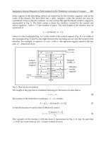
Fig. 5. For Mangin and Parabolic collectors the optical fibre is placed very close to the
secondary mirror by means of a support crossing the collector in its central part, as Fig. 6
illustrates.
Fig. 5. Collector A1 (Mangin60) realized in glass.
Internal Lighting by Solar Collectors and Optical Fibres
7
Fig. 6. Fibre position for Mangin and Parabolic collectors.
2.2 Parabolic collectors
The parabolic system is composed of two mirrors, the primary is parabolic and the
secondary is flat, with or without correction lens: B1 and B2, respectively. The position of the
secondary mirror is analogous of the corresponding Mangin layouts A1 and A3 shown in
Figures 3a and 3c.
Figures 7a and 7b present the standard views of the optical designs for B1 and B2. To
provide a more realistic view of B2, Fig. 7c presents a three-dimensional model of the
Parabolic with lens.
The optical parameters are summarized in Tab. 2 of Sect. 3.1, but for B1 the maximum
reachable EPD is 70mm, f is 65mm (at a wavelength of 580nm), f/# is 0.93 and the maximum
axial angle θ is 28.3°; while for B2 EPD is 71.1mm, f is 65mm, f/# is 0.914 and θ=28.67°.
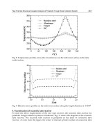
The optical quality of B1 is very good; the total spot diameter is 0.610 mm with a very high
uniformity of light distribution, as shown by the image profiles in Fig. 8. It is useful to
remind that a parabolic mirror is free from on-axis aberrations (spherical and chromatic),
then the spot diagram for the on-axis field is exactly a point (if we do not consider higher
order aberrations). In B2 an additional correction lens allows an improvement of the quality
of this system, decreasing the off-axis aberrations (coma and astigmatism) and the total spot
diameter results 0.598 mm. For B1 and B2 Fig. 8 compares the mean image profiles along a
central image line. The figure evidences that the images of B1 and B2 are larger than those of
the three Mangin collectors in Fig. 4.
B1 was realised by an Italian firm (SILO) as Glass parabolic mirror built by traditional optical
working: EPD is 70mm and f is 65mm for the SILO parabolic mirror. A B2 sample was
acquired among the commercial products available on the market, selecting the Aluminium
Diamond turned parabolic mirror (by Advance – Coherent) with EPD=71.1mm and f=65mm.
The useful features of the parabolic layouts are the optimised optical parameters, which
create high collection efficiency, combined to a large enter pupil, giving a wide effective
area. The output power, analysed in Sect. 3, depends on both efficiency factor and effective
area. Collectors B1 and B2 represent the best solutions optimising these two quantities.
2.3 Conic Cassegrain collector
The optical project of the Catadioptric Concentrator Monoblock (CCM) was developed with
the aim of optimising the optical characteristics of the collector but also its compactness. In
Tables 1 and 2 it is classified as conic Cassegrain and indicated as C1. The first surface is
elliptic and the second one is spherical. The maximum EPD is 56mm, f is 55mm and f/# is
0.98. As for the previous collectors, C1 fulfils the fibre-matching requirements: the output
Optical fibre
Primary
Mirror
Secondary
Mirror
Solar Collectors and Panels, Theory and Applications
8
(a) (b)
(c)
Fig. 7. (a) Zemax optical design of Parabolic B1. (b) Zemax optical design of Parabolic B2. (c )
Zemax 3D model of Parabolic B2.
Fig. 8. Profiles of B1 and B2 images.
Internal Lighting by Solar Collectors and Optical Fibres
9
angle θ=26.98° is within the fibre acceptance angle (28.7°) and the total image diameter
(0.534mm) is considerably shorter that the fibre size (0.6mm).
The optical working principle of this collector is well known: it consists of two optical
elements in a coaxial configuration of Cassegrain type. The C1 scheme is presented in Fig. 9;
while Fig.10a reports the optical design and Fig.10b a 3D model. The characteristics of C1
seemed to be particularly useful for fibre-coupling and the realisation procedure appeared
to be innovative.
C1 was realised in a unique piece of quartz (see Sect. 3.3), obtaining an objective
characterised by extremely reduced dimensions and great mechanical stability. The input
surface is flat and its central part was optically worked to obtain the spherical surface of the
secondary mirror. The primary mirror is aspherical and in its centre there is a non-
aluminised flat zone, which represents the output surface. The crossing of the glass
constituting the concentrator along its entire internal optical path contributes to compensate
the spherical aberration of the mirrors and it allows correcting the aberrations of a primary
mirror with ellipsoid shape. The internal path within the material introduces acceptable
chromatic aberrations.
Successively some samples of CCM were realised in PMMA ((polymethylmethacrylate),
reducing weight and realisation costs (see Sect. 3.3).
The image profile of C1 is compared with those of B2 and A3 in Fig. 11 showing that the C1
image is larger than A3 (the largest Mangin image) but considerably smaller with respect to
B2 (the largest Paraboloid image). The optical quality of this system is good, but lower with
respect to the quality of the two parabolic ones (see Tab. 2 in Sect. 3.1).
The main advantages of C1 are immediately visible comparing the layouts of the six
collectors, the CCM thickness (25mm) is considerably shorter and, being a monoblock, it is
easier to be mounted and aligned. These characteristics of the CCM are a fundamental
advantage since the device is modular and it is supposed to incorporate several collectors in
each tile (illustrated in Sect. 4).
Fig. 9. Layout of CCM: collector C1.
Solar Collectors and Panels, Theory and Applications
10
(a) (b)
Fig. 10. (a) Zemax optical design of conic Cassegrain C1. (b) Zemax 3D model of conic
Cassegrain C1.
Fig. 11. Profile of C1 image, compared to B2 and A3 profiles.
3. Theoretical and experimental comparison of the collectors
3.1 Theoretical efficiency of collectors
Our modular device was composed of units, each of which consisted of a concentrator
coupled to an optical fibre that transported the power to the utilisation point. Characteristics
and performance of the six optical projects were theoretically estimated, calculating in
particular the collection efficiency of each collector coupled to a 5m quartz fibre of size
0.6mm and NA=0.48. Table 2 summarises these optical features to compare the
concentrators presented in Sect. 2.
Table 2 reports the power collection performance for the six concentrators of Tab. 1: the
collector efficiency factor is the ratio output power / input power, while the total efficiency
factor corresponds to the collector coupled to the fibre. The effective area is the surface
effectively exposed to the sun and it was used to calculate the output power theoretically
obtained at fibre end. In this output power calculation the total efficiency factor takes into
Internal Lighting by Solar Collectors and Optical Fibres
11
1
2 3 4 5 6 7 8 9 10 11
Layout
Max.
enter
pupil
diam.
(mm)
Focal
length
(mm)
f/#
number
Image
size
(mm)
Rms spot
diam.
(mm)
Total spot
size (5+6)
(mm)
Collector
efficiency
factor
Total
efficiency
factor
Effective
area (mm
2
)
Output
power
(W)
A1 - STANDARD MANGIN (M1 Spherical, M2 Flat)
40.0 39.8 0.99 0.350 0.163 0.513 0.73 0.64 1230 0.677
A2 - MODIFIED MANGIN I (M1 Spherical, M2 Spherical)
52.0 48.0 0.923 0.418 0.180 0.598 0.73 0.64 2085 1.147
A3 -MODIFIED MANGIN II (M1 Spherical, M2 Allum. Spher. Lens)
62.0 58.1 0.937 0.500 0.094 0.594 0.66 0.58 3004 1.498
B1 - PARABOLIC (M1 Parabolic, M2 Flat)
70.0 65.0 0.93 0.567 0.043 0.610 0.81 0.71 3732 2.279
B2 - PARABOLIC WITH LENS (M1 Parabolic, M2 Allum. Spher. Lens)
71.1 65.0 0.914 0.560 0.038 0.598 0.73 0.64 3909 2.152
C1 - CONIC CASSEGRAIN CCM (M1 Elliptic, M2 Spherical)
56.0 55.0 0.98 0.480 0.054 0.534 0.73 0.64 2082 1.146
Table 2. Collectors characteristics and sunlight collection performance.
account all losses of the collector-fibre system. Data in Table 2 were evaluated considering
the following efficiency factors: 0.9 per mirror surface, 0.95 per glass surface, 0.97 for the 5m
quartz fibre. The effect of the protective glass that should cover the whole tile of collectors
was not taken into account in this table. The input power density value considered was
Solar Collectors and Panels, Theory and Applications
12
860 W/m
2
,
which
is approximately the solar irradiance arriving on the Earth surface in the
best conditions at a latitudes around 45°N. While the standard value of the irradiance
outside the atmosphere is 1367 W/m
2
.
A crucial parameter in this comparative table is the estimation of the final power obtained at
the end of the optical fibre coupled to each collector. The highest output power values
correspond to the two Parabolic B1 and B2, followed by Mangin A3 power value. C1 and A2
reach output power levels slightly lower than Mangin A3, but they are still better than A1.
Even though the C1 image appears to be as good as those of B1 and B2, the output power
obtained by the CCM does not reach the parabolic values. The advantage of the parabolic
optical projects is that they combine high collection efficiency with wide effective area: they
optimise these two quantities maximising the output power. The most compact optical
layout is C1 that allows obtaining high power concentration with reduced aberrations. Table
2 shows that the rms spot of aberrations (lateral dashed spot in Fig. 1) is significantly
reduced for C1, B1 and B2, with respect to all Mangin collectors.
In conclusion if the main purpose is to maximise the output power the parabolic collectors
will be preferred. The CCM will be chosen if we privilege the compactness and the facility to
be mounted and aligned. By a commercial point of view, if the main requirement is to have
a collector easy to be realised at a competitive price the Mangin collector will be the better
solution. On the base of the optical projects described in Sect. 2 and compared in this
section, samples of all collectors were practically realised. The results of their experimental
tests are reported in the next section.
3.2 Experimental tests on realised samples
Several samples of concentrators in Tab. 1 were realised as discussed in Sect. 2 and we
experimentally measured the performance of the realised collectors coupled to an optical
fibre. The experimentation included laboratory tests and field measurements with direct
explosion to the sun. The tests in laboratory were performed using an optical system
reproducing the solar divergence [14]; while the field tests require the employment of
tracking systems to correctly orient the concentrators (discussed in Sect. 4).
Only B1 of Tab. 2 was available as commercial product, while the other samples were
optically manufactured by Italian firms on the base of the optical designs in Sect. 2. The
results for the collection efficiency, which is the ratio between the power measured at fibre
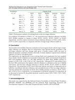
end and the power arriving on the collector effective area, are reported in Table 3. The
experimental values were measured in Florence (Italy) during the month of November
between 11.30 to 12.30 AM.
Taking into account efficiency results, realisation costs and optical system compactness, we
decided to extensively test in real conditions only Mangin60 and CCM. Field tests were
repeated in all seasons of the year and at different hours during the day. The average output
power measured at the end of a 5m quartz fibre was 0.80÷0.85 W for Mangin60 and
0.95÷1.05 W for CCM in Silica. The CCM realised in PMMA (with EPD=56mm, f=53.7 mm
and effective area 2082mm
2
) provided an output power of 0.80÷0.90 W, thus resulting
slightly less efficient than the CCM in Silica. For the plastic realisation of C1 the lower
performance is both due to the use of PMMA instead of Silica (quartz) and to the more
precise optical manufacturing of the Silica C1. Beyond the reduced thickness, easy mounting
and easy aligning, the C1 in PMMA presents a further advantage: it is lighter and cheaper
than C1 in Silica. The tests evidenced that the drawbacks of Silica C1 are heaviness and
Internal Lighting by Solar Collectors and Optical Fibres
13
label Collector
EPD(mm), f(mm),
effective area
(mm
2
)
Theoretical
efficiency at fibre
end (Tab.2 col.9)
Lab. meas.
of efficiency
at fibre end
Field meas.
of efficiency
at fibre end
A1
Mangin 60 in
Glass
60.0, 60.0, 2672 0.64 0.41 0.33
A1
Mangin 40 in
Glass
40.0, 40.0, 1230 0.64 0.41
B1
Paraboloid in
Glass
70.0, 65.0, 3732 0.71 0.39 0.31
B2
Paraboloid
(commercial)
71.1, 65.0, 3909 0.64 0.32 0.33
C1 CCM in Quartz 56.0, 55.0, 2082 0.64 0.54 0.53
Table 3. Experimental efficiency of sunlight collection.
difficulties to realise the aspherical surface and obviously the very high cost for this
realisation. The CCM in PMMA reduces both weight and costs still providing good
collection efficiency.
It is useful to note that the obtained output power is in sunlight, whose luminous efficacy is
much higher than that of electric lighting. The luminous efficacy is 70÷105 lm/W for direct
sunlight and 110÷130 lm/W for diffuse skylight [21]; while for an incandescent lamp it is
10÷18 lm/W [22]. Hence the application to internal illumination exploits also the elevated
luminous efficacy of solar light.
3.3 Plastic collector development
The successive step was the development of plastic optical components, which reduced the
realization costs. Collector C1 was realized both in Silica (quartz) and in PMMA (plastic); it
is important to note that the optical project of C1 ought to be redesigned for the realization
1 2 3 4 5 6 7 8 9 10 11
Layout and
realisation
Max. enter
pupil diam.
(mm)
Focal
length
(mm)
f/#
number
Imag
e size
(mm)
Rms
spot
diam.
(mm)
Total spot
size (5+6)
(mm)
Collector
efficienc
y
factor
Total
efficienc
y factor
Effectiv
e area
(mm
2
)
Output
power
(W)
C1 in
Fused
Silica
56.0 55.0 0.98 0.480 0.054 0.534 0.73 0.64 2082 1.15
C1
realised
in Quartz
56.0 55 0.98 0.8 0.66 0.54 2082 0.97
C2 in
PMMA
(plastic)
56.0 53.7 0.96 0.5 0.075 0.075 0.73 0.64 2082 1.10
C2
realised
in PMMA
56.0 54 0.96 2082 0.85
Table 4. Features and collection performance of Cassegrain CCM collectors.
Solar Collectors and Panels, Theory and Applications
14
in PMMA (polymethylmethacrylate). Table 4 summarises optical parameters and collection
performance of conic Cassegrain CCM collectors: it compares two theoretical optical
projects, C1 in Fused Silica and C2 in PMMA (in italics), to the CCM manufactured in quartz
and plastic. The measurements on C1 realised in quartz were performed in laboratory and
inside a hole of 0.6mm diameter there was 84% of the total energy in the focal plane. The
output power for C2 realised in PMMA is the average of the values obtained in the field
tests.
Two CCM samples are presented in Fig. 14: Fig. 14a shows a C1 in Silica, Fig. 14b a C2 in
PMMA. The optical performance of the two components was comparable, but the weight
was considerably reduced for the plastic optics. The work proceeded modifying the optical
project of collector C2 for being mass produced and for being coupled to a larger optical
fibre (with core diameter 1.2mm and NA=0.48). The final component was an aspherical lens
in PMMA (described in Sect. 5.1) with much reduced width (14.9mm) and weight (24g)
compared to the C1 in quartz (width 23.8mm, weight 136g).
(a) (b)
Fig. 14. (a) Cassegrain collector C1 realized in quartz. (b) Cassegrain collector C2 realized in
plastic.
A further improvement was the use of plastic (or glass) fibre bundles instead of quartz
single fibres. Considering the coupling to the aspherical lens in PMMA, the chosen value for
the core diameter of the single fibre was 1.5mm, to take into account the spot enlargement
and to facilitate the alignment. For the museum application to the illumination of several
very large showcases (3m X 5m), requiring a large number of lighting terminations, fibre
bundles were preferred. Optical fibre bundles made in plastic are very flexible, almost
unbreakable and considerably cheaper than quartz fibre bundles, especially for a diameter
of 1.5mm. Moreover for such a large core diameter a plastic fibre has extremely shorter bend
radius with respect to a quartz fibre (as discussed in Sect. 5.4).
4. Sun tracking systems to support and orient the collectors
4.1 Sun tracking method
The sun tracking technique was studied [15], experimented and tested under working
conditions. Suitable mechanical systems, to support and move the optical system, were
Internal Lighting by Solar Collectors and Optical Fibres
15
designed and built. The movements to align the optical collectors in the sun direction were
performed in two directions by using an equatorial configuration: the directions being on
the temporal axis and on the declination axis.
The methodology to track the sun position employed a double guiding system that uses two
complementary procedures. The first one provides the preliminary orientation, then the
second realises the fine positioning and adjustments. The first tracking system is of a passive
type and drives the motors to correctly orient the collectors every day of the year. The
second one is of a dynamic type and employs an optical pointing system. The core of this
active tracking system is the sun pointer, which works as a double pinhole camera [16]. The
pointer has two sensors, with decreasing field of view, that are used in sequence, improving
the precision of the sun tracking. The system tracks the sun position with an angular
precision higher than 0.1°. It is reliable and adaptable to all weather conditions and
environmental variations. In the case of sun shading or temporary sun absence, the system
provides a realignment of collectors in a few seconds. Furthermore, it is able to compensate
for possible errors in the positioning of the device, which should be placed with the
temporal axis parallel to the Earth’s axis.
The solar collecting device is modular and its basic unit is a tile holding four concentrators.
The tiles are mounted on a support whose orientation follows the sun position using a
tracking system. This modular solar plant can be placed either on the roof or in the
playground of a building.
4.2 The tile with 4 Mangins and 4 Cassegrains
Mangin and CCM Cassegrain concentrators were mounted on tiles of four collectors, as
shown in Fig. 12a and 12b, respectively. The use of a small tile facilitates the alignment
operations and improves the possibility of its massive reproduction, so the tile dimensions
were 14cm x 14cm. Reduced size of the tile and system geometry makes it adaptable to the
available space and to specific architectural requirements.
(a) (b)
Fig. 12. (a ) Tile of 4 Mangins.(b) Tile of 4 CCM Cassegrains.